

Parker AC10 Easy Start Manual

Parker AC10 Frequency Inverter (to 22kW)
Easy Start Guide
CAUTION:
1)Do not re-set while the motor is rotating
2)Perform parts replacement after discharge is finished
3)Do not connect output terminals to the power supply
L2
P
L2
B
P
B
V
U
U
W
V
W
The Parker AC10 Frequency Inverter range is
available to order from inverterdrive.com
This guide is intended to complement the user manual provided by the manufacturer.
It is provided as a basic introduction to the product for Inverter Drive Supermarket customers.
It should not be used as a replacement for the manual issued by the manufacturer.
This product is not a safety device. All safety considerations including but not
limited to Emergency Stop provision should be assessed separately and are
outside the scope of this guide.
Issue 3
20181109

Easy Start Guide
Parker AC10 Series Inverter (to 22kW)
Contents
Page 1
Page 2
Page 3
Page 4
Page 5
Page 6
Page 7
Page 8
Page 9
Page 10
Contents
Power and Motor Connections (Single Phase)
Power and Motor Connections (Three Phase)
Motor Connections - Star and Delta
Parameters - Overview
Parameters to set before use
How to set a Parameter value
How to Operate the Inverter from the keypad
How to enable Sensorless Vector mode
How to connect and configure a Potentiometer
for remote speed control
How to connect and configure a Run Forward or
Run Reverse switch
Page 11
Page 12
Page 13
Page 14
This guide has been produced by The Inverter Drive Supermarket Ltd.
All content, including but not limited to graphics, text and procedures copyright The Inverter
Drive Supermarket and must not be reproduced or altered without prior written permission.
How to connect and configure a Run/Stop switch
with Forward/Reverse selection
How to configure “3-Wire” control with Run/Stop
pushbuttons and Forward/Reverse selection
Brake Resistor Connection
How to Reset the Inverter to Factory Defaults
©
Page 1

Easy Start Guide
Parker AC10 Series Inverter (to 22kW)
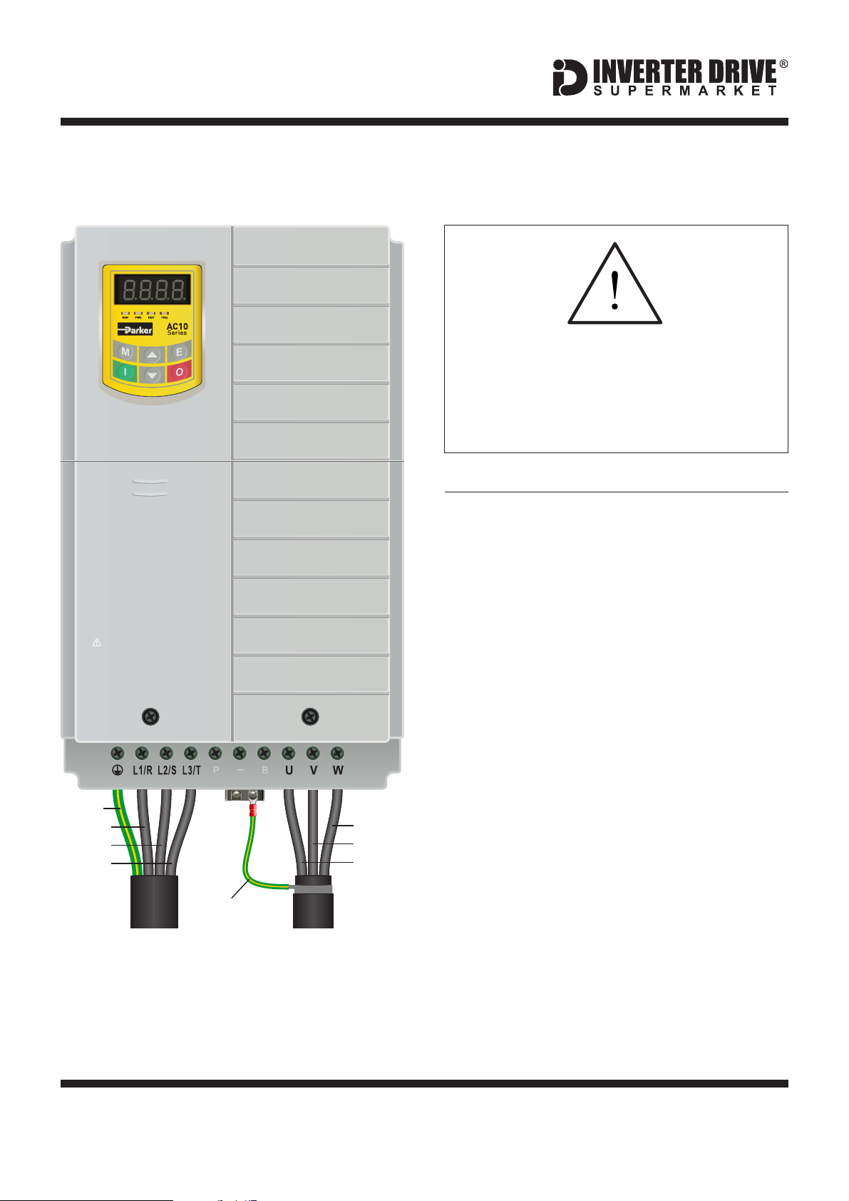
1. Power and Motor Connections (Single Phase)
Before commencing, confirm that the Inverter and
all cables are completely isolated from the power
supply, have been isolated for at least 5 minutes
and that the motor is not turning.
L3/TL2/SL1/R
P
P
L3/T
L2/SL1/R
Earth
Live
Neutral
CAUTION:
1)Do not re-set while the motor is rotating
Supply
2)Perform parts replacement after discharge is finished
3)Do not connect output terminals to the power supply
Size 2
L2
P
B
P
B
Earth
Live
Neutral
Notes: Important:
V
U
W
Phase
Phase
Phase
Screen / Armour
MotorSupply
The main illustration above is based on the
0.75kW rating (size 1). The supply terminals
for ratings from 1.1kW (size 2) is also shown.
The L3/T terminal (if present) can be ignored.
The order of the three motor phases
determines the initial direction the motor turns.
This guide has been produced by The Inverter Drive Supermarket Ltd.
All content, including but not limited to graphics, text and procedures copyright The Inverter
Drive Supermarket and must not be reproduced or altered without prior written permission.
Use screened or armoured cable between the
Inverter and Motor and ensure it is grounded
as shown.
The motor must be separately earthed.
The supply must match the Inverter
specification.
©
Page 2
Easy Start Guide
Parker AC10 Series Inverter (to 22kW)
2. Power and Motor Connections (Three Phase)
Before commencing, confirm that the
Inverter and all cables are completely
isolated from the power supply, have
been isolated for at least 5 minutes and
that the motor is not turning.
Notes:
CAUTION:
1)Do not re-set while the motor is rotating
2)Perform parts replacement after discharge is finished
3)Do not connect output terminals to the power supply
Earth
Phase
Phase
Phase
Screen or
Armour
Phase
Phase
Phase
The illustration on the left is based on the 22kW
400V model. The terminal layout for other
ratings is similar.
The order of the three supply phases is not
important. They should be connected to the
terminals marked L1/R, L2/S and L3/T as
shown. In some cases, these terminals may be
marked L1, L2 and L3 only.
The order of the three motor phases
determines the initial direction the motor turns.
This can be reversed by physically swapping
any two motor phases. Or by changing the
Inverter parameters.
Use screened or armoured cable between the
Inverter and Motor. To minimise
electromagnetic interference, ensure the
cable screen is grounded as shown.
The motor must be separately earthed.
Supply
Motor
The supply must match the Inverter
specification.
This guide has been produced by The Inverter Drive Supermarket Ltd.
All content, including but not limited to graphics, text and procedures copyright The Inverter
Drive Supermarket and must not be reproduced or altered without prior written permission.
©
Page 3
Easy Start Guide
Parker AC10 Series Inverter (to 22kW)
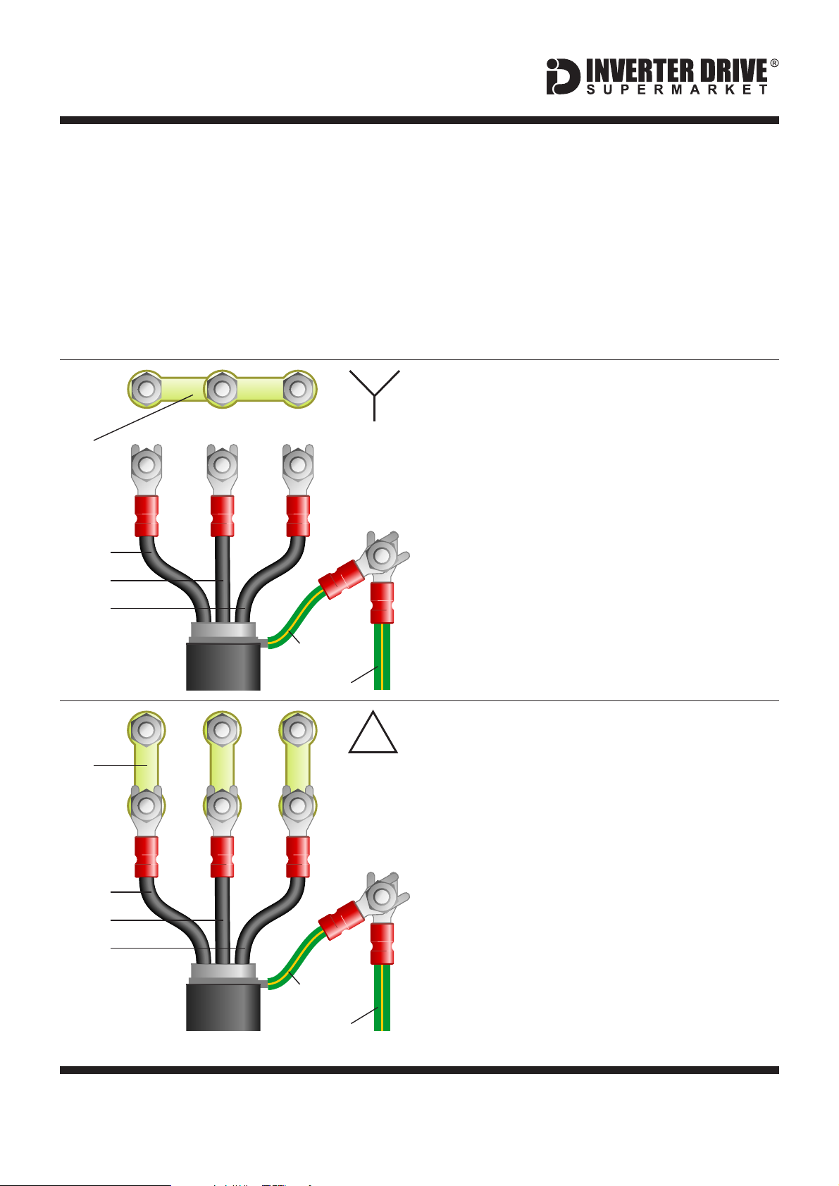
3. Motor Connections - Star and Delta
Dual voltage induction motors typically include
terminal boxes with six points. The points can
be connected together with links in one of two
ways to suit one of the two rated voltages.
The two ways of connecting the links are
shown below. These are known as “Star” (the
higher voltage) or “Delta” (the lower voltage).
Link
Phase
Phase
Phase
STAR
The selection of Star or Delta is not optional
and must match the supply voltage.
Dual voltage motor nameplates include
symbols to represent voltage and full load
current in each configuration.
Delta is represented by a triangle and star by a
Y (Wye).
3.1 Motor connected in STAR (or Wye):
For safety purposes, Star (shown opposite) is
the default configuration for small motors
(usually to 3kW) and is sometimes known as
“two at one side”.
Only two links are required for Star. Double-up
the links if changing from Delta to allow the
motor to be changed back in future.
The order of the three phases determines the
direction the motor turns.
Link
Phase
Phase
Phase
Screen
Earth
Screen
Earth
DELTA
Note that the manufacturer recommends that
the cable screen is earthed at both ends and
the motor and Inverter are earthed separately.
3.2 Motor connected in DELTA:
The link configuration is shown in the
illustration opposite and is sometimes referred
to as “three-a-breast”.
The order of the three phases determines the
direction the motor turns.
Note that the manufacturer recommends that
the cable screen is earthed at both ends and
the motor and Inverter are earthed separately.
This guide has been produced by The Inverter Drive Supermarket Ltd.
All content, including but not limited to graphics, text and procedures copyright The Inverter
Drive Supermarket and must not be reproduced or altered without prior written permission.
©
Page 4
 Loading...