

Page 1

Cont.1
8903/IM and 8903/IP
Ethernet Communications
Interfaces
Technical Manual
HA500522U001 Issue 2
Compatible with 890 Firmware Version 3.2 onwards
Copyright 2008 Parker SSD Drives, a division of Parker Hannifin Ltd.
All rights strictly reserved. No part of this document may be stored in a retrieval system, or transmitted in any
form or by any means to persons not employed by a Parker SSD Drives company without written permission
from Parker SSD Drives, a division of Parker Hannifin Ltd . Although every effort has been taken to ensure the
accuracy of this document it may be necessary, without notice, to make amendments or correct omissions.
Parker SSD Drives cannot accept responsibility for damage, injury, or expenses resulting therefrom.
WARRANTY
Parker SSD Drives warrants the goods against defects in design, materials and workmanship for the period of 12
months from the date of delivery on the terms detailed in Parker SSD Drives Standard Conditions of Sale IA500504.
Parker SSD Drives reserves the right to change the content and product specification without notice.
Page 2
Cont.2
WARNING!
During commissioning, remove the fuses (or trip the circuit breaker) on your 3-
phase supply.
Make sure the power is OFF, and that it cannot be switched on accidentally whilst you
are working.
REFER TO YOUR MAIN PRODUCT MANUAL FOR SPECIFIC SAFETY
INFORMATION ABOUT THE DEVICE YOU ARE CONTROLLING
IMPORTANT: Please read this information BEFORE installing the equipment.
Intended Users
This manual is to be made available to all persons who are required to install, configure or
service equipment described herein, or any other associated operation.
The information given is intended to highlight safety issues, EMC considerations, and to enable
the user to obtain maximum benefit from the equipment.
Application Area
The equipment described is intended for industrial motor speed control.
Personnel
Installation, operation and maintenance of the equipment should be carried out by qualified
personnel. A qualified person is someone who is technically competent and familiar with all
safety information and established safety practices; with the installation process, operation and
maintenance of this equipment; and with all the hazards involved.
Safety
All control and signal terminals are SELV, i.e. protected by double insulation.
EMC
In a domestic environment this product may cause radio interference in which case the user may
be required to take adequate counter-measures.
This equipment contains electrostatic discharge (ESD) sensitive parts. Observe static control
precautions when handling, installing and servicing this product.
Safety Information
!
Page 3

Cont.3
CAUTION!
At any time, there may be a loss of motor control and separate/independent application
measures should be taken to ensure that such loss of motor control cannot present a safety
hazard.
RISK ASSESSMENT
Under fault conditions, power loss or unintended operating conditions, the drive may not
operate as intended. In particular:
• Stored energy might not discharge to safe
levels as quickly as suggested, and can still
be present even though the drive appears to
be switched off
• The motor's direction of rotation might not
be controlled
• The motor speed might not be controlled
• The motor might be energised
A drive is a component within a drive system that may influence its operation or effects under
a fault condition. Consideration must be given to:
• Stored energy • Supply disconnects • Sequencing logic • Unintended
operation
Safety Information
!
Page 4

Contents
Contents Page
Cont.4
ETHERNET COMMUNICATIONS INTERFACE 1
Introduction ..................................................................................................... 1
Product Features ........................................................................................................1
Product Codes ........................................................................................................... 1
Installation....................................................................................................... 2
Wiring the System ...................................................................................................... 5
LED Indications ................................................................................................ 6
Network Status LED (NS)............................................................................................. 6
• Modbus/TCP ........................................................................................... 6
• Ethernet/IP ..............................................................................................6
Module Status LED (MS).............................................................................................. 7
•
Modbus/TCP ........................................................................................... 7
• Ethernet/IP ..............................................................................................7
LINK/Activity LED........................................................................................................ 7
Drive Diagnostics............................................................................................. 8
•
The Ethernet MMI View............................................................................. 8
• Parameter Descriptions ............................................................................ 8
Configuring the Ethernet System..................................................................... 9
Step 1: Configuring the Ethernet TechCard using DSE 890........................................... 9
• Step 1.1: Inserting an Ethernet Function Block ........................................... 9
•
Step 1.2: Attaching Fieldbus Connectors................................................. 10
•
Step 1.3 : Configuring the Fieldbus Connectors....................................... 11
•
DSE Data Types .....................................................................................13
• Ethernet Data Types ............................................................................... 13
•
Conversion of DSE Type < > Ethernet Type ............................................ 13
Step 2: Configuring the PLC/SCADA Supervisor.........................................................14
• Modicon Momentum..............................................................................14
• Allen Bradley ControlLogix .....................................................................16
•
TS8000 Operator Station using DSI8000 ................................................ 18
Configuring DSE to Connect over Ethernet .................................................... 22
Appendix A: Ethernet Error Codes................................................................. 23
Appendix B : DSE/Ethernet Conversion Rules ............................................... 29
•
LOGIC Type Connector .........................................................................29
•
INTEGER Type Connector.......................................................................29
•
VALUE Type Connector ..........................................................................30
Page 5

1
8903/IM 8903/IP Ethernet Communications Interfaces
ETHERNET COMMUNICATIONS INTERFACE
Introduction
This manual describes the Parker SSD Drives' Ethernet Communications Interface Options
(TechCards).
Product Features
• Available for 890 products
• Easy plug-in installation
• Suitable for use with drive models:
890CD Common Bus Drive and 890SD Standalone Drive
using 890 firmware version 3.2 onwards
• Galvanically isolated bus electronics
• 10/100Mbit operation
• LEDs to indicate network and module status
• Supports Modbus/TCP protocol (8903/IM only)
• Supports Ethernet/IP protocol (8903/IM only)
• Supports RTNX protocol to connect to Drive System Explorer
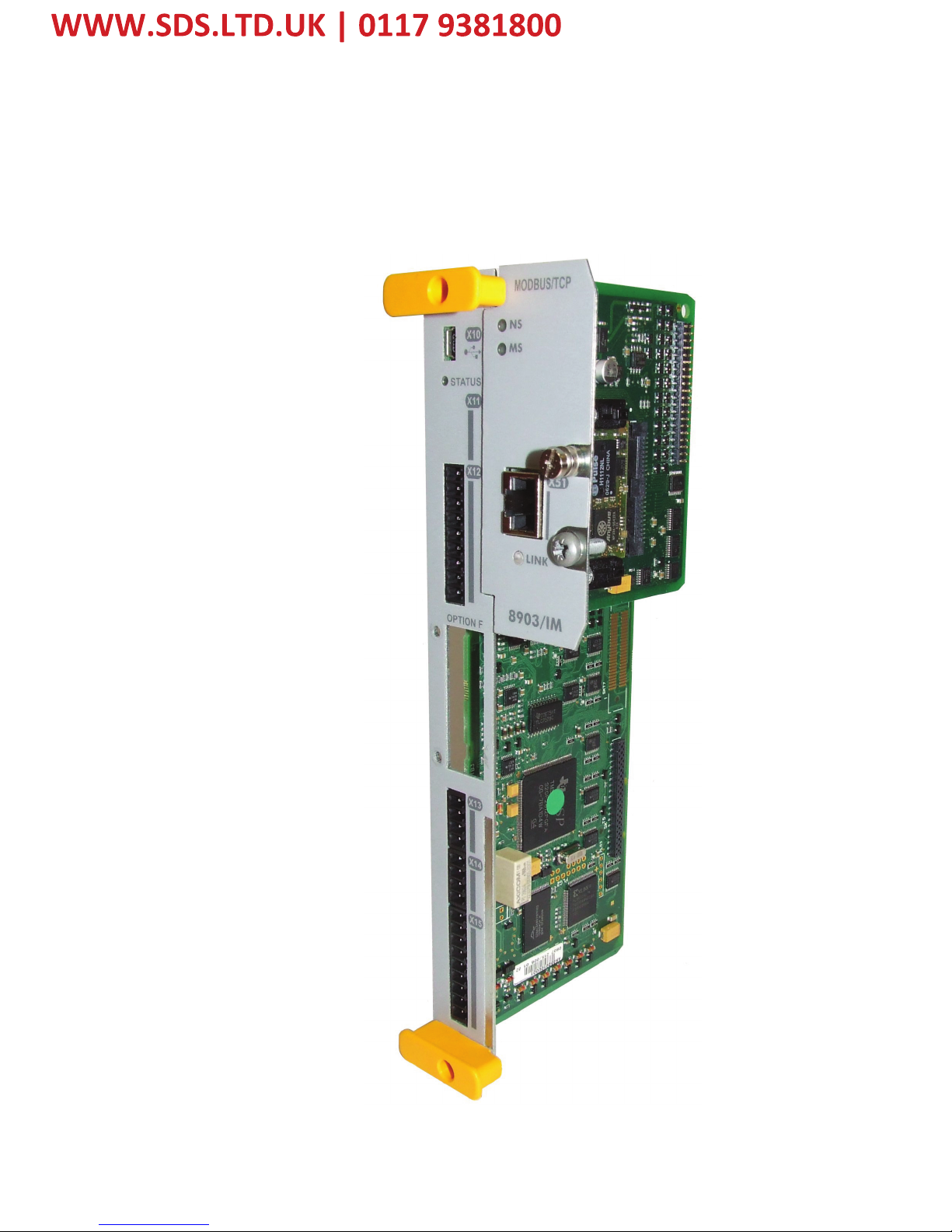
1 NETWORK and MODULE status LEDs 3 LINK Activity LED
2 RJ45 Ethernet Interface 4 Connector to Control Board
Product Codes
Part Number: 8903/IM/00 – Ethernet Modbus/TCP TechCard
8903/IP/00 – Ethernet/IP TechCard
Figure 1. Ethernet TechCard
1
4
3
2
Page 6

2
8903/IM 8903/IP Ethernet Communications Interfaces
Installation
WARNING!
Before installing, ensure that the
drive wiring is electrically isolated
and cannot be made “live”
unintentionally by other personnel.
Wait 5 minutes after disconnecting
power before working on any part of
the system or removing the covers
from the drives.
To Remove the Control Board
1. Remove the blank covers, each secured
by a single screw, that fit over the
TechCard holes.
2. Loosen the top and bottom screws in
the handles of the Control Board (2).
3. Pull gently on the handles and slide the
Control Board (2) out of the drive.
Note: Save the blank cover and screw for
future use. The drive should not be
operated without a TechCard or blank
cover. When fitted, these maintain the
drive's IP20 rating.
Figure 3. Front of 890 drive showing
Control Board fitted
Figure 2. 890 showing Control Board
withdrawn, with Options fitted
3
2
1
1
2
Page 7

3
8903/IM 8903/IP Ethernet Communications Interfaces
Fitting the TechCard
The TechCard fits onto the Control Board.
1. Insert the connector into the TechCard as shown. The legs of the connector will protrude
through into the connector on the other side of the TechCard.
2. Press the assembly into the TOP connector (adjacent to terminals X10, X11 and X12) on
the Control Board. Ensure that the front panel of the TechCard overlaps the front of the
Control Board. Ease the connector at the TechCard so that the two pcb's are parallel when
viewed on edge.
Figure 4. Fitting the connector to the TechCard
Page 8
4
8903/IM 8903/IP Ethernet Communications Interfaces
Re-fitting the Control Board
1. Slide the board into the drive, engaging the edges of the boards into the slots. Push until the
back edge of the Control Board pcb locates with the connectors in the drive.
2. Tighten in position using the top and bottom screws in the blue handles of the Control
Board.
3. Screw the TechCard in position using the captive screw on the front of the TechCard.
Figure 5. 890 Control Board with TechCard fitted
Page 9

5
8903/IM 8903/IP Ethernet Communications Interfaces
Wiring the System
Connection to the drive(s) from a PC, or PLC for example, is made using a cable fitted with
standard RJ45 connectors at both ends. The cable plugs into the PLC, for example, and into the
socket on the Ethernet techbox.
Note: When connecting to one drive direct from PC/PLC, you must use a crossover cable.
RJ45 (Standard) Pin Details
Pin Signal
1 TD+
2 TD3 RD+
4 Termination
5 Termination
6 RD7 Termination
8 Termination
Cable Specifications
Cable Type Maximum Node-to-Node Distance
(m)
CAT5 100
CAT5E 100
P
L
C
P
L
C
S
w
i
t
c
h
/
H
u
b
Figure 6. Typical connections to a PLC
Page 10
6
8903/IM 8903/IP Ethernet Communications Interfaces
LED Indications
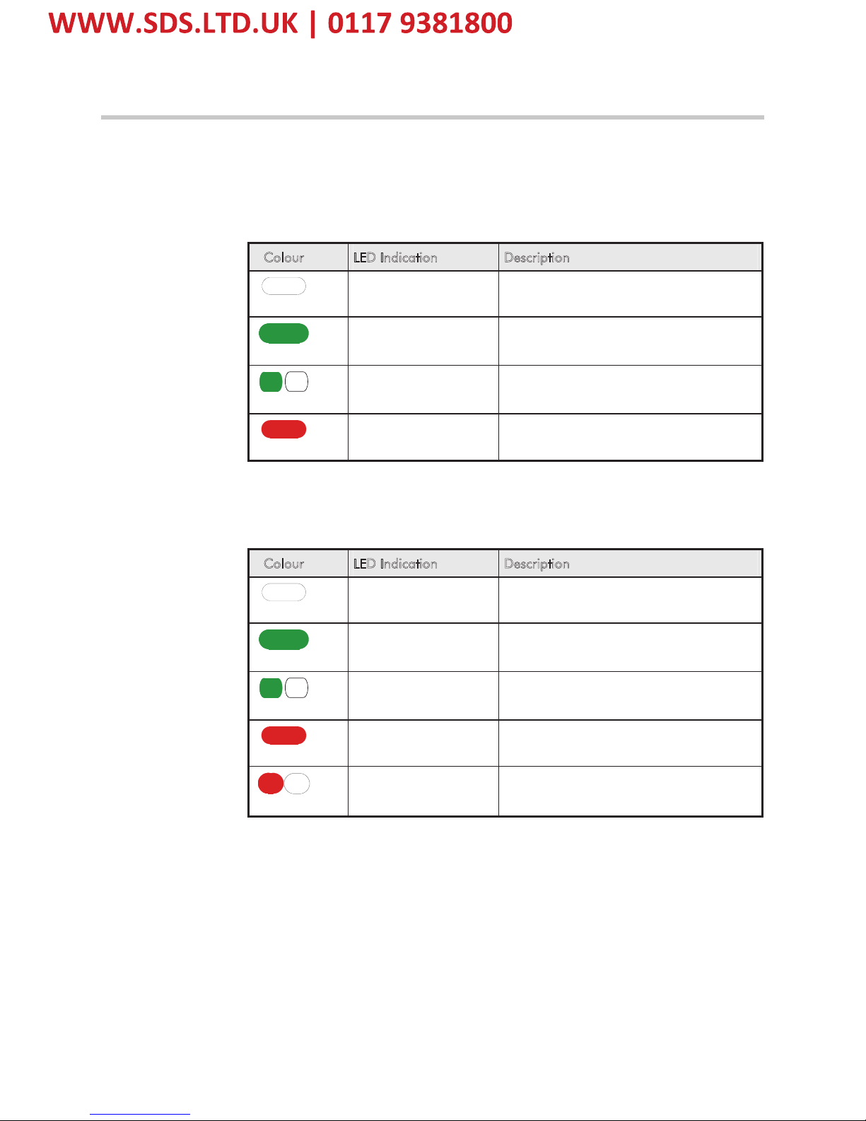
Network Status LED (NS)
Note: A test sequence is performed on this LED during start-up.
Modbus/TCP
Colour LED Indication Description
OFF
OFF No power or no IP Address set
GREEN
ON Normal operation
GREEN
FLASHING Waiting for connections
RED
ON
Duplicate IP Address
Figure 7. Modbus/TCP NS LED
Ethernet/IP
Colour LED Indication Description
OFF
OFF No power or no IP Address set
GREEN
ON
On-line, one of more connections
established
GREEN
FLASHING On-line, no connections established
RED
ON
Duplicate IP address
RED
FLASHING One or more connections timed out
Figure 8. Ethernet/IP NS LED
Page 11

7
8903/IM 8903/IP Ethernet Communications Interfaces
Module Status LED (MS)
Note: A test sequence is performed on this LED during start-up.
Modbus/TCP
Colour LED Indication Description
OFF
OFF No power
GREEN
ON Normal operation
GREEN
FLASHING Major fault
RED
ON
Duplicate IP Address
RED
FLASHING Minor fault
Figure 9. Modbus/TCP MS LED
Ethernet/IP
Colour LED Indication Description
OFF
OFF No power
GREEN
ON Controlled by a Scanner in Run state
GREEN
FLASHING
Not configured, or Scanner in idle
state
RED
ON
Major fault
RED
FLASHING Recoverable fault(s)
Figure10. Ethernet/IP MS LED
LINK/Activity LED
Colour LED Indication Description
OFF
OFF No link, no activity
GREEN
ON Link established
GREEN
Flickering Activity
Figure 11. LINK/Activity LED
Page 12

8
8903/IM 8903/IP Ethernet Communications Interfaces
Drive Diagnostics
The Ethernet MMI View
Diagnostic information is available through the MMI.
MMI Menu Map
1
SETUP
2
COMMUNICATIONS
3
ETHERNET
RTNX IP ADDRESS
890 IP ADDRESS
890 SUBNET MASK
890 GATEWAY
Parameter Descriptions
RTNX IP ADDRESS Read Only Range: NOT CONNECTED,
XXX.XXX.XXX.XXX
The IP Address of the computer running Drive System Explorer (DSE) is displayed if
connected to the 890 via Ethernet.
If DSE is not connected, then NOT CONNECTED is displayed. Note – this is also
displayed if there has been no communications activity from the connected DSE in the
last 5 minutes.
8
90 IP ADDRESS Read Only Range: XXX.XXX.XXX.XXX
IP Address of the 890.
8
90 SUBNET MASK Read Only Range: XXX.XXX.XXX.XXX
Subnet Mask being used.
8
90 GATEWAY Read Only Range: XXX.XXX.XXX.XXX
Gateway Address being used.
Page 13
9
8903/IM 8903/IP Ethernet Communications Interfaces
Configuring the Ethernet System
To configure the Ethernet system, complete the steps below.
Step 1: Configuring the Ethernet TechCard using DSE 890
Step 1.1: Inserting an Ethernet Function Block
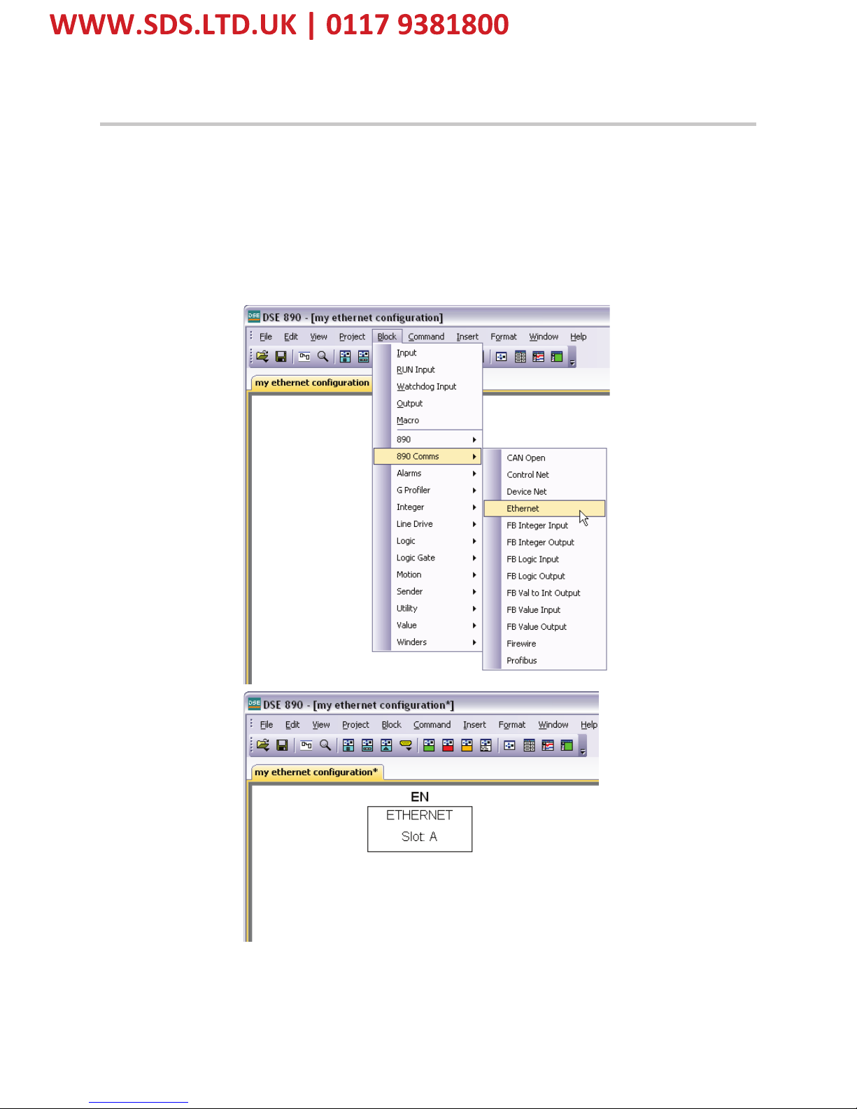
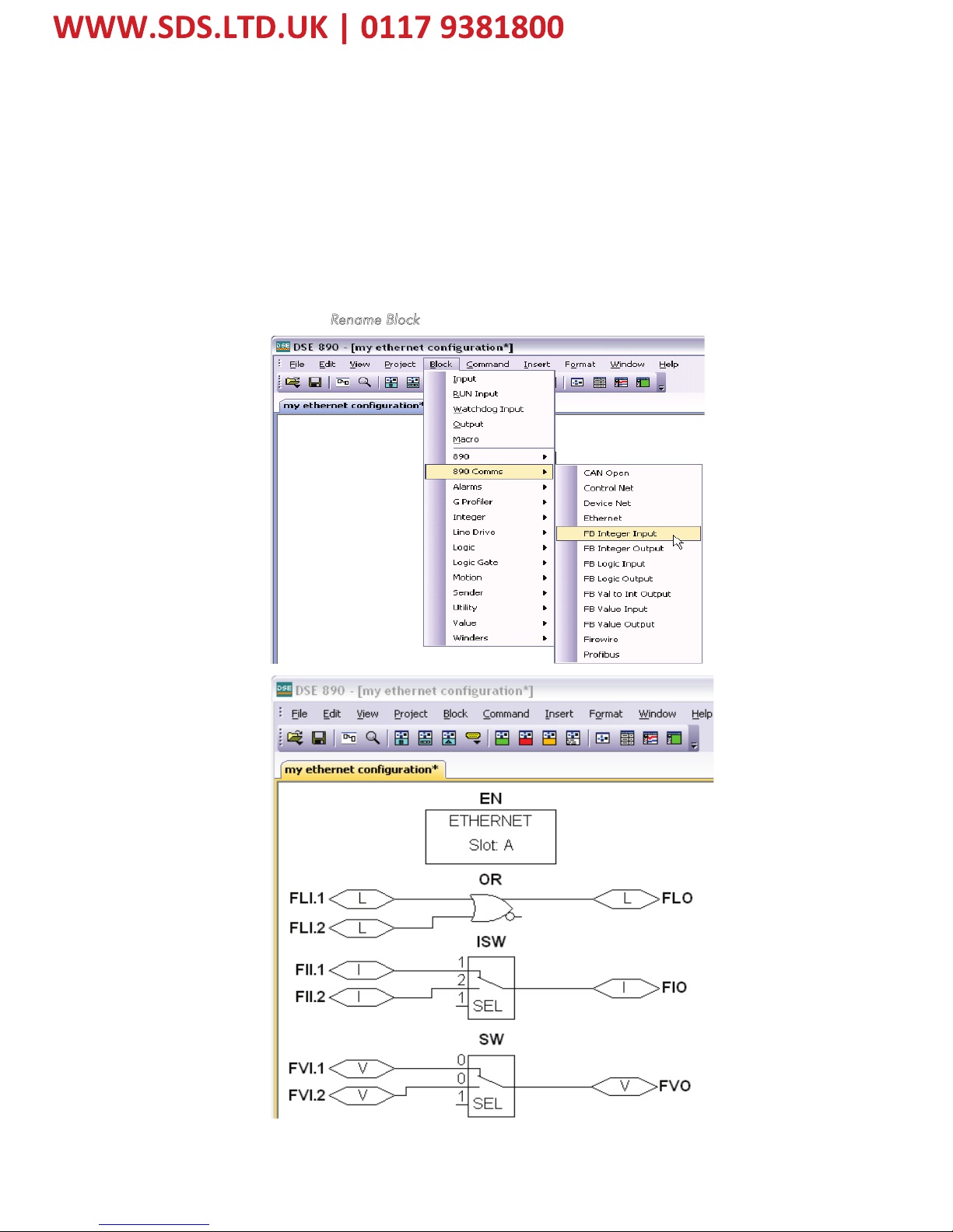
Display your configuration page. Click on the Block menu at the top of the screen.
1. Move the cursor down to select "890 Comms" and select "Ethernet".
2. Click to attach the block icon to the cursor. Move the icon to where you want on the screen.
Click again to release the icon.
Figure 12. Configuration showing EN Function Block
Page 14
10
8903/IM 8903/IP Ethernet Communications Interfaces
Step 1.2: Attaching Fieldbus Connectors
Seven fieldbus connector types are available:
FB Logic Input FB Integer Input FB Value Input
FB Logic Output FB Integer Output FB Value Output
FB Val to Int Output
Input connector : the data is sent from PLC ¤ 890
Output connector : the data is sent from 890 ¤ PLC
The fieldbus connectors must be added before they will appear in the EtherNet function block.
Note: The function block and connectors can be renamed by using the right mouse button and
selecting R
ename Block.
Figure 13. Configuration showing EN Function Block and Fieldbus Connectors
Page 15

11
8903/IM 8903/IP Ethernet Communications Interfaces
Step 1.3 : Configuring the Fieldbus Connectors
Double-click on the function block to display the dialog below. The fieldbus connectors (inputs
and outputs) are assignable in the function block along with their data type to/from the PLC.
The Option Slot, 32-bit Order, IP Address, Subnet Mask and Gateway Address can also be
selected.
To configure the input and output connectors you have placed in the configuration:
1. Expand the Inputs and Outputs trees to reveal the registers. By default the trees each have
one register. To add more registers click on
adjacent to New…
2. Select the drop-down menu in the Input column to choose the required input/output
connector on the Register. For example below, Register 1 "Input" is shown with the
possible fieldbus selections that have been placed in the configuration: FII.1 (Fieldbus
Integer Input 1), FLI.1 (Fieldbus Logic Input 1), FVI.1 (Fieldbus Value Input 1) etc.
Page 16

12
8903/IM 8903/IP Ethernet Communications Interfaces
3. Select the drop down menu in the Type column to choose the required PLC type on
Register 1, for example.
4. Set up all the input/output registers in a similar way.
5. Set up the option parameters:
"Option Slot" = A (top). The Ethernet TechCard can only be fitted in the OPTION A slot of
the drive. This is the default setting for "Option Slot".
“32bit order” is set to either “Low Word First” or “High Word First”. This refers to how
32-bit data types, i.e. SINT32, UINT32 and FLOAT are encoded on Ethernet. If Ethernet/IP
is being used, this should always be Low Word First. If Modbus/TCP is being used, it
depends on the master.
• Low Word First is sometimes referred to as “Modicon Mode” and is used when the
least significant 16-bits are sent in a lower register number than the most significant
16-bits, i.e. Little-endian.
• High Word First is sometimes referred to as “IEEE Mode” and is used when the most
significant 16-bits are sent in a lower register number than the least significant 16-bits,
i.e. Big-endian.
“IP Address”, “subnet mask” and “gateway” are used to set the IP parameters. If set to
0.0.0.0 they may be configured over Ethernet, e.g. by using the Address Resolution
Protocol (ARP).
Remember:
♦ The order and size of the inputs in the DSE Ethernet configuration MUST match the
order and size of the outputs from the PLC configuration.
♦ The order and size of the outputs in the DSE ControlNet configuration MUST match
the order and size of the inputs to the PLC configuration.
Page 17

13
8903/IM 8903/IP Ethernet Communications Interfaces
DSE Data Types
Data Type Description Range
LOGIC Logic False (F) and True (T)
INTEGER 32-bit signed integer -2,147,483,648 to 2,147,483,647
VALUE 32-bit fixed point value -32768.0 to 32767.9999
Ethernet Data Types
Data Type Description Range Bytes Used
SINT16 16-bit signed integer -32,768 to 32,767 2
SINT32 32-bit signed integer -2,147,438,648 to
2,147,483,647
4
UINT16 16-bit unsigned integer 0 to 65,535 2
USINT32 32-bit unsigned integer 0 to 4,294,967,295 4
FLOAT 32-bit IEEE-754 floating-point
value
1.19209290e-38 to
3.4028235e+38
4
Conversion of DSE Type < > Ethernet Type
The DSE fieldbus connectors are each assigned an Ethernet "Type" as described in "Step 1.3 :
Configuring the Fieldbus Connectors" on page
11.
The conversion between the DSE type and the PLC type is performed automatically (refer to
Appendix B : DSE/Ethernet Conversion Rules, page 29).
Any PLC type can be assigned to a fieldbus connector.
Page 18

14
8903/IM 8903/IP Ethernet Communications Interfaces
Step 2: Configuring the PLC/SCADA Supervisor
This section contains examples for configuring a Modicon PLC, an Allen-Bradley PLC and the
TS8000 Operator Interface. The Ethernet Technology Box supports the ModBus/TCP protocol
and the Ethernet/IP protocol.
Modicon Momentum
1. Start a new program and select
the PLC processor and chassis
type used in your project. Our
example uses an M1 980-20
Momentum PLC. Stay offline
until you are ready to
download the program.
2. Place an MSTR block in the
ladder logic. MSTR blocks
move data from the PLC data
table to the drive or from the
drive to the PLC data table.
Two MSTR blocks are
necessary for a Read and Write
operation.
3. Right click over the MSTR
block. This will access the
Register Editor. Use the
Register Editor to configure
the block. The MSTR block
has two types of operations:
Read or Write. The first
register defines the type of
operation. In our case address
40100 is used for write
command and address 40200 is
used for read command. A
value of 1 in the data column
defines a Write operation. A
value of 2 in the data column
defines a Read operation.
Figure 14. PLC Ladder Logic
showing MSTR Blocks
Figure 15. Read Registers
Page 19

15
8903/IM 8903/IP Ethernet Communications Interfaces
4. The second register contains the error status. Refer to Appendix A for a list of the error
codes. The PLC software also has help files that contain a list of error codes.
5. The third register defines the data length (address 40102 or address 40202). The value
in the data column depends on which parameter set that has been selected in the drive.
The value can be smaller than or equal to the selected parameter set.
6. The fourth register defines the Read and Write locations of the data in the PLC (address
40103 or address 40203). For a Read function, this value is set to 1, and for a Write
function this value is set to 257.
7. Registers 5, 6, 7 and 8 define the IP address on the Ethernet network (address 40104 or
address 40204). Our example shows the data registers starting at locations 40150 and
40250.
8. When using a Modicon PLC, the “32bit Word Order” parameter in the Ethernet
function block must be set to “Low Word First”. This applies to Modicon products and
most other manufactures using the ModBus/TCP protocol.
Figure 16 Write Registers
Page 20

16
8903/IM 8903/IP Ethernet Communications Interfaces
Allen Bradley ControlLogix
9. Start a new program and select the PLC processor and chassis type that is used in your
project. Our example uses a 1756-L55A processor and 1756-A7/B rack. Remain Offline
until you are ready to download the program.
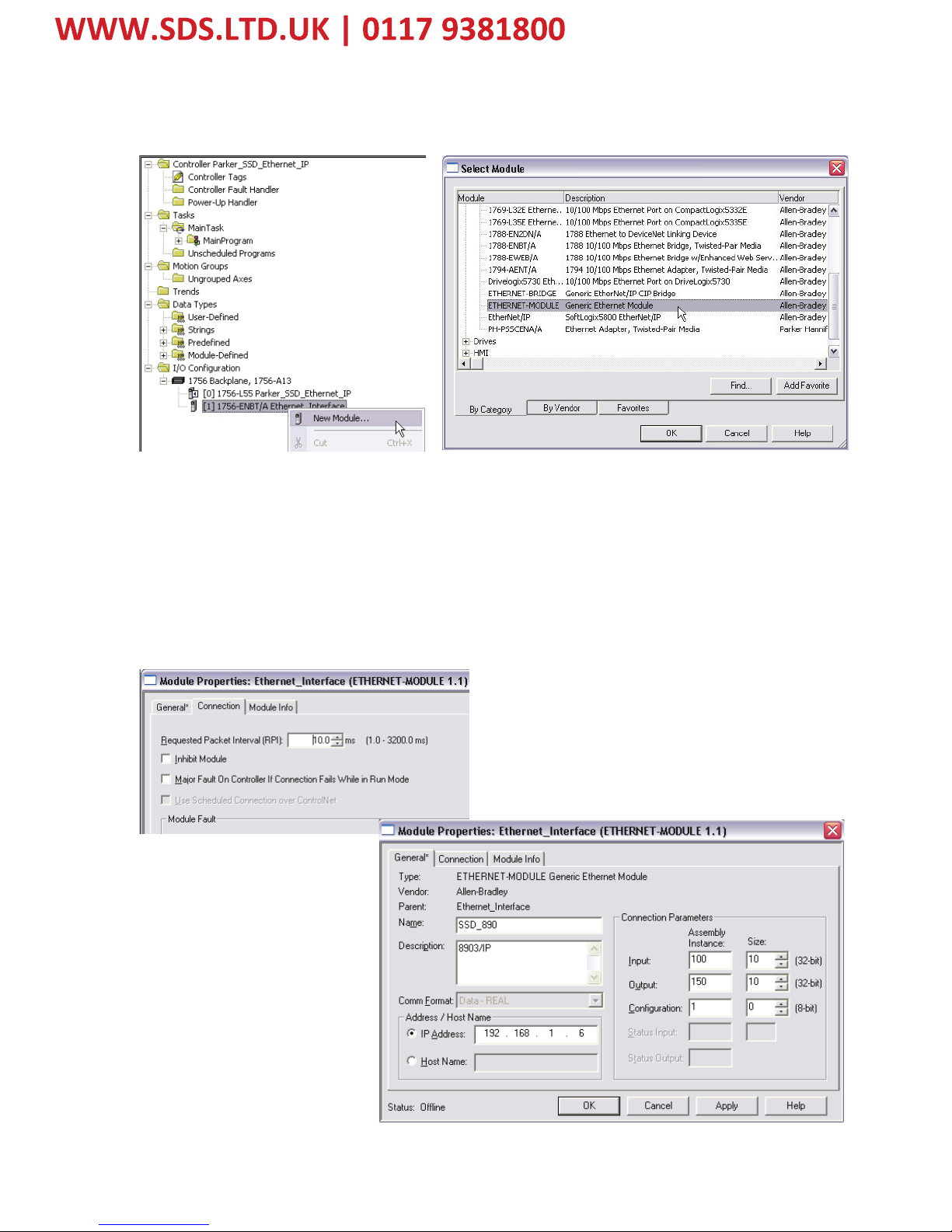
10. Using the I/O Configuration insert the Ethernet interface that will be installed. Right click
on the I/O Configuration, select New Module. Our example uses 1756-ENBT/A. Input the
desired IP address and slot in the PLC. Refer to Figures 17 and 18.
Figure 17. Ethernet Interface Selection
Figure 18. Ethernet Interface Setup
Page 21
17
8903/IM 8903/IP Ethernet Communications Interfaces
11. Right click on the Ethernet Interface Module, select New Module. This screen will allow
the selection of the Generic Ethernet Module. Refer to Figure 19.
12. Input the desired module name and IP address. The Comms format will be DATA Int if 16-
bit signed integer, or Data-REAL if 32-bit floating point. The Input Assembly Instance is
100 and the Output Assembly Instance is 150. Refer to Figure 20.
13. Click on Next to change the Requested Packet Interval (RPI). The default value of 10ms
should be sufficient. If the RPI is set below 5ms unreliable communications may be
experienced. Refer to Figure 20.
Figure 19. Generic Ethernet Module Select
Figure 20. Generic Ethernet Module Setup
Page 22

18
8903/IM 8903/IP Ethernet Communications Interfaces
14. When completed with the setup of the Generic Ethernet Module it can be downloaded to
the PLC. For testing purposes it is not necessary to program Ladder Logic in the PLC. The
data can be accessed and monitored via Controller Tags. Refer to Figure 21.
TS8000 Operator Station using DSI8000
15. Select Modbus TCP/IP protocol for Ethernet Port. The TS8000 is the Master.
Fi
g
ure 21. Controller Tags
Page 23

19
8903/IM 8903/IP Ethernet Communications Interfaces
16. Set the Slave IP address to match the one configured in the 890.
Page 24

20
8903/IM 8903/IP Ethernet Communications Interfaces
17. The name of the Slave can be changed and additional Slaves added.
18. Create Tags for reading and writing variables.
Create either an Integer or a Real variable and map it to the correct Slave.
Page 25

21
8903/IM 8903/IP Ethernet Communications Interfaces
Always select Holding Register for both 16-bit and 32-bit data types. DO NOT SELECT
“Holding Registers (32-bit)”.
To write to the first Input variable declared in DSE, the Register number (Element) is set to
00001. To write to the second variable declared in DSE, the Register number is 00002 if the
first Input variable is a 16-bit data type or 00003 if it is a 32-bit data type.
To read the first Output variable declared in DSE, the Register number is set to 00257. To read
the second variable declared in DSE, the Register number is 00258 if the first Output variable is
a 16-bit data type or 00259 if it is a 32-bit data type.
If variable is SINT16 or UINT16, select Data Type “Word as Word”. If variable is SINT32 or
UINT32, select Data Type “Word as Long”. If variable is REAL, select Data Type “Word as
Real”.
Page 26

22
8903/IM 8903/IP Ethernet Communications Interfaces
Configuring DSE to Connect over Ethernet
It is possible to connect DSE to any 890 Drive with an Ethernet option to allow Configuration
Installation, Update and On-Line Monitoring. This is an alternative to the USB connection, with
the advantage of speed and remote connection. Note – it is not possible to Install Firmware over
Ethernet, this must always be done over USB.
Click on the Comm Port icon and select IP.
Enter IP address of 890 Drive to connect to.
If a 890 Drive is already connected on the same LAN as the PC running DSE when DSE is
launched, the Drive will appear in the list of available Comm Ports.
Page 27

23
8903/IM 8903/IP Ethernet Communications Interfaces
Appendix A: Ethernet Error Codes
Error Codes (Modbus Plus & SY/MAX Ethernet)
Error Status Register: 4xxxx + 1 (HEX)
Error Coding: Mmss where M = major code, m = minor code, ss = sub code
n 16#1001: User initiated abort.
n 16#20ss: Invalid command errors.
n 16#30ss: Modbus slave exception response.
n 16#4001: Inconsistent Modbus slave response.
n 16#5001: Inconsistent network response.
n 16#6mss: Routing failure.
n 16#F001: Selected S985 option is not present.
Invalid Command Errors
Error Status Register: 4xxxx+1 (HEX)
Error Coding: Mmss where M = major code, m = minor code, ss = sub code
n 2001: Invalid operation type.
n 2002: User parameter changed.
n 2003: Invalid length.
n 2004: Invalid offset.
n 2005: Invalid length + offset.
n 2006: Invalid SDDA (Slave Device Data Area).
n 2007: Invalid SDNA (Slave Device Network Address).
n 2008: Invalid SDNR (Slave Device Network Routing).
n 2009: Invalid route ( = own address).
n 200A: Global read request > available.
n 200B: Peer Cop conflict on write/read global data.
n 200C: Bad pattern for change address request.
n 200D: Bad address for change address request.
Ethernet/Modbus Slave Exception Response
Error Status Register: 4xxxx+1 (HEX)
Error Coding: Mmss where M = major code, m = minor code, ss = sub code
n 3001: Illegal function request (not available in slave).
n 3002: Illegal data address (not configured in slave).
n 3003: Illegal data value (Read/Write data not valid).
n 3004: Not used (unknown error).
n 3005: Slave accepted long duration program command.
n 3006: Requested function cannot be performed due to long command in progress.
n 3007: Slave rejected long program command.
Page 28

24
8903/IM 8903/IP Ethernet Communications Interfaces
Routing Failures
Error Status Register: 4xxxx + 1 (HEX)
Error Coding: Mmss where M = major code, m = minor code, ss = sub code
Routing failure error code: 6mjj
n 6m01: No response.
n 6m02: Program access denied.
n 6m03: Node is offline and unable to communicate.
n 6m04: Exception response received.
n 6m05: Route node data paths busy.
n 6m06: Slave device down.
n 6m07: Bad destination address.
n 6m08: Invalid node type in routing.
n 6m10: Slave rejected the Modbus command.
n 6m20: Slave forgot initiated translation.
n 6m40: Unexpected master output path received.
n 6m80: Unexpected response received.
Note: m = index to location in the routing information where routing problem was discovered.
0 = local network station
1 = first device in route
2 = second device in route, etc.
Page 29
25
8903/IM 8903/IP Ethernet Communications Interfaces
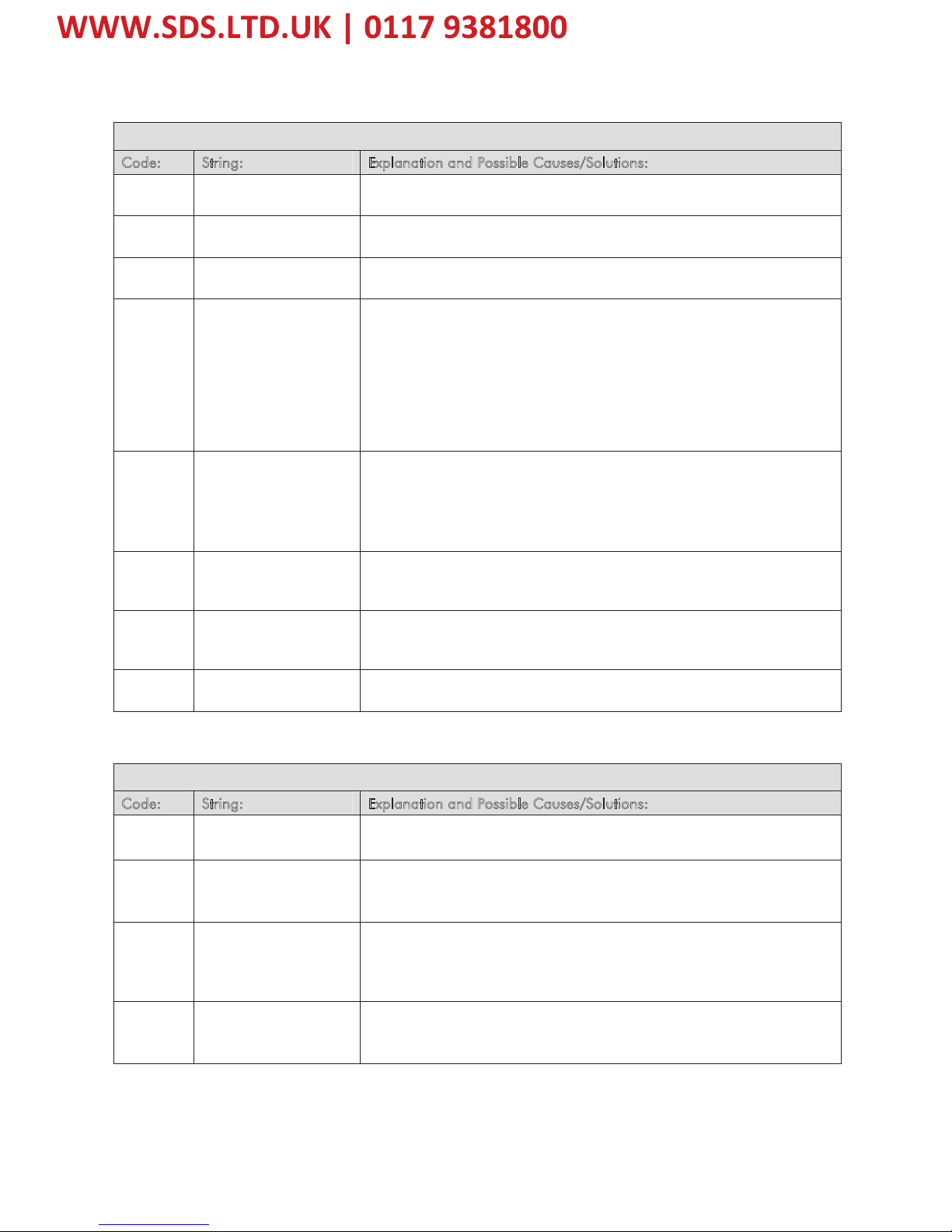
Error Codes (Allen Bradley Communication Modules)
Module Faults: 16#0001 - 16#00ff
Code: String: Explanation and Possible Causes/Solutions:
16#0004 Connection Request
Error: Bad Segment
The controller is attempting to make a connection to the module and has
received an error.
16#0005 Connection Request
Error: Bad Class
The controller is attempting to make a connection to the module and has
received an error
16#0008 Service Request Error:
Unsupported Service
The controller is attempting to request a service from the module and
has received an error.
16#0009 Module Configuration
Invalid: parameter
error.
Note: Additional Error
Information for this
fault will be displayed
as a hex code on the
Connection Tab.
The configuration for the module is invalid.
The module configuration may have been changed in the Tag Monitor
or programmatically. Verify that the configuration is valid by using the
module configuration software to validate your configuration.
16#000c Service Request Error:
Invalid mode/state for
service request
The controller is attempting to request a service from the module and
has received an error. Ensure that the module is not faulted. §
For a Discrete I/O module, this indicates that the module still has limited
communications, but has a Major Fault or is currently being Flash
Updated. Refer to the Module Info tab to determine the exact cause.
16#0013 Module Configuration
Invalid: data size too
small.
The configuration for the module is invalid – not enough configuration
data was sent.
16#0015 Module Configuration
Invalid: data size too
large.
The configuration for the module is invalid – too much configuration
data was sent.
16#0016 Service Request Error:
Unknown Object
The controller is attempting to request a service from the module and
has received an error.
Module Faults: 16#0100 - 16#01ff
Code: String: Explanation and Possible Causes/Solutions:
16#0100 Connection Request
Error: Module in Use.
The controller is attempting to make a specific connection to a module
and the module cannot support more than one of these connections.
16#0103 Service Request Error:
CIP transport class not
supported.
The controller is requesting services not supported by the module.
16#0106 Connection Request
Error: Module owned
and configured by
another controller.
The Connection Request to this module has been rejected due to an
Ownership conflict with another Owner (e.g., another Controller). This
may occur with modules such as output modules which only allow a
single Owner to configure and control its outputs.
16#0108 Connection Request
Error: Connection type
not supported.
The controller is requesting a connection type not supported by the
module.
Page 30

26
8903/IM 8903/IP Ethernet Communications Interfaces
Module Faults: 16#0100 - 16#01ff
Code: String: Explanation and Possible Causes/Solutions:
16#0109 Connection Request
Error: Invalid
connection size
Note: Additional Error
Information for this
fault will be displayed
as the tag name
associated with the
connection instance
number that has the
fault.
The controller is attempting to set up a connection with the module and
cannot – the size of the connection is invalid.
The controller may be attempting to connect to a tag in a producing
controller whose size does not match the tag in this controller.
16#0110 Connection Request
Error: Module not
configured
The controller is attempting to set up a Listen Only connection with the
module and cannot – the module has not been configured and
connected to by an Owner (e.g., another Controller).
This controller is not an Owner of this module since it is attempting to
establish a Listen-Only connection, which requires no module
configuration. It cannot connect until an Owner configures and connects
to the module first.
16#0111 Requested Packet
Interval (RPI) out of
range.
The Requested Packet Interval (RPI) specified is invalid for this module or
for a module in the path to this module.§
For Listen-Only connections: the RPI set by the owner of this module is
slower than the one requested. Either increase the requested RPI or
decrease the RPI the owner controller is using. See the Connection tab
for valid RPI values.
16#0113 Connection Request
Error: Module
connection limit
exceeded.
This module (or a module in the path to this module) has exceeded its
connection capacity. Reduce the total number of connections used by this
module.
16#0114 Electronic Keying
Mismatch: Electronic
Keying product code
mismatch.
The Product Code of the actual module hardware does not match the
Product Code of the module created in the software.
Electronic Keying failed for this module. You may have a mismatch
between the module created in the software and the actual module
hardware.
16#0115 Electronic Keying
Mismatch: Electronic
Keying product type
mismatch.
The Product Type of the actual module hardware does not match the
Product Type of the module created in the software.
Electronic Keying failed for this module. You may have a mismatch
between the module created in the software and the actual module
hardware.
16#0116 Electronic Keying
Mismatch: Major
and/or Minor revision
invalid or incorrect
The Major and/or Minor revisions of the module do not match the Major
and/or Minor revisions of the module created in the software.
Ensure that you have specified the correct Major and Minor Revision if
you have chosen Compatible Module or Exact Match keying.
Electronic Keying failed for this module. You may have a mismatch
between the module created in the software and the actual module
hardware.
Page 31

27
8903/IM 8903/IP Ethernet Communications Interfaces
Module Faults: 16#0100 - 16#01ff
Code: String: Explanation and Possible Causes/Solutions:
16#0117 Connection Request
Error: Invalid
Connection Point.
Note: Additional Error
Information for this
fault appears as the
tag name associated
with the controller to
controller (C2C) that
has the fault.
The controller is attempting to make a connection to the module and has
received an error.
Another controller owns this module and has connected with a
Communications Format different than the one chosen by this controller.
Ensure that the Communications Format chosen is identical to that
chosen by the first owner controller of the module.
The controller may be attempting to connect to a non-existent tag in a
producing controller.
16#0118 Module Configuration
Invalid: format error
The configuration for the module is invalid.
16#0119 Connection Request
Error: Module does not
have an owner
The controller is attempting to set up a listen-only connection with the
module and cannot – the module does not have an owner.
This fault may temporarily occur when the system is powered up and will
be cleared when an owner controller connects to and configures the
module.
16#011a Connection Request
Error: Out of
Connection Resources
The controller is attempting to set up a connection with the module and
cannot – resources required are unavailable.
Module Faults: 16#0200 - 16#02ff
Code: String: Explanation and Possible Causes/Solutions:
16#0203 Connection timed out. The connection to this module has been interrupted causing a loss of
communication.
Ensure that the module has not been removed and is still functioning
and is receiving power.
Ensure that the network connection to this module has not been
interrupted.
Note: If a connection to an output module times out and the output
module supports Fault Mode and the output module is still functioning,
its outputs will transition to the configured Fault Mode.
16#0204 Connection Request
Error: Connection
request timed out.
The controller is attempting to make a connection to the module and the
module is not responding.
The controller is not able to communicate with the module. Ensure that
the module has not been removed and is still functioning and is
receiving power.
Ensure you have entered the correct slot number. Ensure that the
network connection to the module has not been interrupted.
16#0205 Connection Request
Error: Invalid
parameter.
The controller is attempting to set up a connection with the module and
has received an error – a parameter is in error.
16#0206 Connection Request
Error: request size too
large.
The controller is attempting to set up a connection with the module and
has received an error – the request size is too large.
Ensure that the path to this module is sufficiently close to the controller.
Page 32

28
8903/IM 8903/IP Ethernet Communications Interfaces
Module Faults: 16#0300 - 16#03ff
Code: String: Explanation and Possible Causes/Solutions:
16#0301 Connection Request
Error: Out of buffer
memory.
The controller is attempting to set up a connection with the module and
has received an error – a module in the path is out of memory.
The controller may be attempting to connect to a tag in a producing
controller that is not marked as being produced.
The controller may be attempting to connect to a tag in a producing
controller. That tag may not be configured to allow enough consumers.§
Reduce the size or number of connections through this module.
One of the network modules between the module and the controller may
be out of memory. Check network configuration of the system.
The module may be out of memory. Check system configuration and
capabilities of module.
16#0302 Connection Request
Error: Out of
communication
bandwidth.
The controller is attempting to set up a connection with the module and
has received an error – a module in the path has exceeded its
communication bandwidth capacity. Increase the Requested Packet
Interval (RPI).
Distribute the load on another bridge module.
16#0303 Connection Request
Error: No bridge
available.
The controller is attempting to set up a connection with the module and
has received an error – a module in the path has exceeded its
communication bandwidth capacity. Distribute the load on another
bridge module.
16#0311 Connection Request
Error: Invalid port.
The controller is attempting to set up a connection with the module and
has received an error.
16#0312 Connection Request
Error: Invalid link
address.
The controller is attempting to set up a connection with the module and
has received an error – an invalid link address has been specified. A link
address can be a slot number, a network address, or the Remote I/O
Rack number and starting group.
Ensure that the chosen slot number for this module is not greater than
the size of the rack.
16#0315 Connection Request
Error: Invalid segment
type.
The controller is attempting to set up a connection with the module and
has received an error – the connection request is invalid.
16#0317 Connection Request
Error: Connection not
scheduled.
The controller is attempting to set up a connection with the module and
has received an error.
16#0319 Connection Request
Error: No secondary
resources available in
redundant chassis.
The controller is attempting to set up a connection with the module and
has received an error – the redundant module does not have the
necessary resources to support the connection.
Reduce the size or number of connections through this module or add
another Controller.
16#031d Connection Request
Error: Tag not
published.
The controller is attempting to connect to a tag in a producing controller
and has received an error.
The controller may be attempting to connect to a tag in a producing
controller and that tag is not marked as ‘published.
16#031e Connection Request
Error: Cannot
consume tag.
The controller is attempting to connect to a tag in a producing controller
and has received an error.
The controller is attempting to connect to a tag in a producing controller
and that tag has already been used by too many consumers. Increase
the maximum number of consumers on the tag.
Page 33

29
8903/IM 8903/IP Ethernet Communications Interfaces
Appendix B : DSE/Ethernet Conversion Rules
The rules governing the conversion between DSE data types and Ethernet data types are given
below. Note carefully that some conversions will result in rounding, limiting and truncation of
the original value
LOGIC Type Connector
Data from PLC Data to DSE
From SINT16 to LOGIC
Zero
Non-zero
False
True
From SINT32 to LOGIC
Zero
Non-zero
False
True
From UINT16 to LOGIC
Zero
Non-zero
False
True
From UINT32 to LOGIC
Zero
Non-zero
False
True
From FLOAT to LOGIC
Zero
Non-zero
False
True
Data from DSE Data to PLC
From LOGIC to SINT16
False
True
0
1
From LOGIC to SINT32
False
True
0
1
From LOGIC to UINT16
False
True
0
1
From LOGIC to UINT32
False
True
0
1
From LOGIC to FLOAT
False
True
0.0
1.0
INTEGER Type Connector
Data from PLC Data to DSE
From SINT16 to INTEGER
-32,768 to 32,767
-32,768 to 32,767
From SINT32 to INTEGER
-2,147,483,648 to 2,147,483,547 -2,147,483,648 to
2,147,483,547
From UINT16 to INTEGER
0 to 65,535
0 to 65,535
From UINT32 to INTEGER
0 to 4,294,967,295
0 to 2,147,483,647
limits apply
From FLOAT to INTEGER
32-bit IEEE floating-point
-2,147,483,648 to
2,147,483,547
Fractional part rounded
Data from DSE Data to PLC
From INTEGER to SINT16
-2,147,483,648 to 2,147,483,647 -32768 to 32767
limits apply
From INTEGER to SINT32
-2,147,483,648 to 2,147,483,647 -2,147,483,648 to
2,147,483,647
From INTEGER to UINT16
-2,147,483,648 to 2,147,483,647 0 to 65,535
limits apply
From INTEGER to UINT32
-2,147,483,648 to 2,147,483,647 0 to 2,147,483,647
limits apply
From INTEGER to FLOAT
-2,147,483,648 to 2,147,483,647 32-bit IEEE floatingpoint
Page 34

30
8903/IM 8903/IP Ethernet Communications Interfaces
VALUE Type Connector
Data from PLC Data to DSE
From SINT16 to VALUE
-32,768 to 32,767
-32,768.0 to 32,767.0
From SINT32 to VALUE
-2,147,483,648 to 2,147,483,547 -32,768.0 to 32,767.0
limits apply
From UINT16 to VALUE
0 to 65,535
0.0 to 32,767.0
limits apply
From UINT32 to VALUE
0 to 4,294,967,295
0.0 to 32,767.0
limits apply
From FLOAT to VALUE
32-bit IEEE floating-point -32,768.0 to
32,767.9999
limits apply
Data from DSE Data to PLC
From VALUE to SINT16
-32,768.0 to 32,767.9999
-32,768 to 32,767
limits apply/ rounding
applies
From VALUE to SINT32
-32,768.0 to 32,767.9999
-32768 to 32,767
limits apply/ rounding
applies
From VALUE to UINT16
-32,768.0 to 32,767.9999
0 to 32767
limits apply/ rounding
applies
From VALUE to UINT32
-32,768.0 to 32,767.9999
0 to 32767
limits apply/ rounding
applies
From VALUE to REAL
-32,768.0 to 32,767.9999
32-bit IEEE floatingpoint
Page 35

31
8903/IM 8903/IP Ethernet Communications Interfaces
ISS. MODIFICATION
ECN No. DATE DRAWN CHK'D
1 Initial Issue (HA500522U001).
New Terms and Conditions document number.
17852
(20358)
03/04/08 CM KJ
2 Small corrections to pages 10 & 21 17852 21/04/08 CM KJ
FIRST USED ON
MODIFICATION RECORD
8903/IM and 8903/IP Ethernet
Communications Interfaces
DRAWING NUMBER
ZZ500522C001
SHT. 1
OF 1
 Loading...