

Page 1
6000 Series
Programmer’s Guide
Compumotor Division
Compumotor
Parker Hannifin Corporation
p/n 88-014540-01
Page 2
User Information
!
WARNING
!
Because software controls machinery, test any software control for safety
under all potential operating conditions. Failure to do so can result in
damage to equipment and/or serious injury to personnel.
6000 Series products and the information in this user guide are the proprietary property of Parker Hannifin Corporation or its licensers, and
may not be copied, disclosed, or used for any purpose not expressly authorized by the owner thereof.
Since Parker Hannifin constantly strives to improve all of its products, we reserve the right to change this user guide and software and
hardware mentioned therein at any time without notice.
In no event will the provider of the equipment be liable for any incidental, consequential, or special damages of any kind or nature
whatsoever, including but not limited to lost profits arising from or in any way connected with the use of the equipment or this user guide.
© 1991-97, Parker Hannifin Corporation
All Rights Reserved
Motion Architect is a registered trademark, and Motion Builder, Servo Tuner, Motion OCX Toolkit, CompuCAM and DDE6000 are trademarks
of Parker Hannifin Corporation.
Microsoft and MS-DOS are registered trademarks, and Windows, DDE, Visual Basic, and Visual C++ are trademarks of Microsoft Corporation.
Wonderware is a registered trademark, and InTouch and NetDDE are trademarks of Wonderware Corporation.
Motion Toolbox is a trademark of Snider Consultants, Inc.
LabVIEW is a registered trademark of National Instruments Corporation.
Technical Assistance
North America and Asia:
Compumotor Division of Parker Hannifin
5500 Business Park Drive
Rohnert Park, CA 94928
Telephone: (800) 358-9070 or (707) 584-7558
Fax: (707) 584-3793
FaxBack: (800) 936-6939 or (707) 586-8586
BBS: (707) 584-4059
e-mail: tech_help@cmotor.com
Internet: http://www.compumotor.com
Motion & Control
Contact your local automation technology center (ATC) or distributor, or ...
Europe
Parker Digiplan
21 Balena Close
Poole, Dorset
England BH17 7DX
Telephone: +44 (0)1202 69 9000
Fax: +44 (0)1202 69 5750
(non-German speaking)
:
Germany, Austria, Switzerland:
HAUSER Elektronik GmbH
Postfach: 77607-1720
Robert-Bosch-Str. 22
D-77656 Offenburg
Telephone: +49 (0)781 509-0
Fax: +49 (0)781 509-176
Product Feedback Welcome
E-mail: 6000user@cmotor.com
Page 3

Change Summary
6000 Series Programmer’s Guide
Re v D
Rev D – summary of changes (minor)
• Removed references to the Motion Architect User Guide. Motion Architect no longer
ships with the printed manual. An on-line Adobe Acrobat PDF version is available from our web
site (http://www.compumotor.com).
• Clarified Command Value Substitution guidelines with a “rule of thumb” (see page 6).
• Error programming correction:
the error program (see page 31).
• DLL documentation clarification and correction (see pages 51-62):
- WN956000.DLL is a
- The DLL functions SetNTParam, SetNTMultiCardAddress, and SetDevice return FALSE (“0”) if
the function is successful and TRUE (non-zero value) if the function is unsuccessful.
• Sending ERRLVL1 to the first unit in an RS-232 daisy-chain does not set all other units to
ERRLVL1. You must send ERRLVL1 to each unit individually. (see page 72)
• GOWHEN correction: A preset GO command that is already in motion
new profile using the GOWHEN and GO sequence of commands. (this is true as of rev 4.1 firmware)
DO NOT use the ERRORP CLR command to cancel the branch to
32-bit DLL to be used for Windows 95.
can (not “cannot”) start a
Rev C – summary of changes (MAJOR)
• Updated to accommodate 4.x firmware enhancements (see topics below) and the ZETA6104.
• The presentation of programming examples was modified so that you can copy them from the
Help system (in Motion Architect) or from the PDF file (on our www.compumotor.com web
site) and paste them directly into your program.
• Added documentation to support
• Incorporated the Following User Guide (see Chapter 6).
• New sections:
- Programming Scenario....................................................... Page 8
- Controlling Multiple Serial Ports ......................................... Page 70
- RS-485 Multi-drop............................................................ Page 75
- Setup Parameters
- ZETA610n Internal Drive Setup ............................................ Page 82
- Servo Setup..................................................................... Page 98
- RP240 Remote Operator Panel ............................................. Page 130
- Host Computer Interface..................................................... Page 143
- Graphical User Interface (GUI) Development Tools.................... Page 144
- Compiled Motion Profiling................................................. Page 163
- On-the-Fly Motion ........................................................... Page 178
- Registration.................................................................... Page 182
- Synchronizing Motion ...................................................... Page 186
- Chapter 6: Following
- Status Commands ............................................................. Page 232
• New back cover with quick-reference material.
(list of commands for common setup parameters)........ Page 78
(incorporated the Following User Guide ).......... Page 191
all 6000 products.
READ ON ...
for a summary of the enhancements implemented in firmware revision 4.x.
mmm
Page 4

Topic Description
Commanded Direction
Reversal (CMDDIR)
Enhancement: The commanded direction polarity reversal command (CMDDIR) is available for the
615n series, the 6270, and all stepper products (610n, AT6n00, 620n). The CMDDIR command
allows you to reverse the direction that the controller considers to be the “positive” direction; this
also reverses the polarity of the counts from the feedback devices. Thus, using the CMDDIR command,
you can reverse the referenced direction of motion without the need to (a) change the connections to
the drive or motor and the feedback device, or (b) change the sign of motion-related commands in
your program.
(SEE_PG._97_OR_101)
Compiled Motion New Feature: (SEE_PG._163)
Related commands (new):
FOLRNF .... Numerator of Final Slave-to-Master Ratio, Preset Moves
GOBUF...... Store a Motion Segment in Compiled Memory
PLN ......... Loop End, compiled motion
PLOOP...... Loop Start, compiled motion
POUTA...... Output on Axis 1, compiled motion
POUTB...... Output on Axis 2, compiled motion
POUTC...... Output on Axis 3, compiled motion
POUTD...... Output on Axis 4, compiled motion
[
SEG ]..... Number of Segments Available In Compiled Memory
TSEG........ Transfer Number of Segments Available, Compiled Memory
VF ........... Final Velocity
Existing commands, modified to support compiled motion:
GOWHEN .... Conditional GOs allowed in compiled motion
PCOMP...... Pre-Compile a Program
PRUN........ Run a Pre-Compiled Program
PUCOMP .... Un-Compile a Program
[
SS ] ...... Bit #29 set if compiled memory 75% full, bit #30 set if 100% full
.............. Bit #31 is set if a compile (PCOMP) failed; cleared on power-up,
.............. reset, or after a successful compile. (See Status Reporting,
.............. Additions below for a list of typical causes.)
TRGFN...... Execute GOWHENs or start new master cycle in compiled motion
TSS ......... (see [ SS ] description above)
Contouring (Circular
Interpolation)
Continuous Command
Execution Mode
(COMEXC1)
Enhancement: As of Rev 4.1, contouring is now available for all multi-axis products, steppers
and servos.
(SEE_PG._153)
Enhancement: On-The-Fly changes (pre-emptive motion). In addition to velocity (V),
acceleration (A & AA), and deceleration (AD & ADA), you may now change the positioning mode (MC &
MA), the distance (D), and the Following ratios (FOLRN & FOLRD). These changes will affect the
subsequent GO command executed while moving; thus, this new enhancement is referred to as “preemptive GOs.” (SEE_PG._178)
When pre-processing subsequent moves, the subsequent move may now be executed as soon as the
next GO command is executed. Previous to revision 4.0, the subsequent move could not be executed
until all moves on all axes were completed.
Drive Configuration
& Reset
Enhancements:
New commands added to set up the drive component of the 610n: (SEE_PG._82)
DACTDP .... Enable/disable active damping for speeds greater than 3 rps.
.............. (config. procedure: see the ZETA6104 Installation Guide)
DAREN...... Enable/disable anti-resonance. Anti-resonance is inhibited at or
.............. below 3 rps, and if active damping is enabled.
DELVIS .... Enable/disable electronic viscosity for speeds at or below 3 rps.
.............. (config. procedure: see the ZETA6104 Installation Guide)
DAUTOS .... Enable/disable automatic current standby mode in which current
.............. to the motor (
& torque) is reduced by 50% if no pulses are sent
.............. for 1 second. Full current is restored upon the next pulse.
DMTIND .... Motor inductance (used only for active damping—DACTDP).
DMTSTT .... Motor static torque (used only for active damping—DACTDP).
DWAVEF .... Motor waveform (required for matching the motor to the drive).
615n only: As of Rev 4.1, you may use the new DRESET command to reset the internal drive
independent of the internal controller. The purpose of the DRESET command is to clear fault
conditions with the internal drive.
Encoder Polarity Reversal
(ENCPOL)
Enhancement: The encoder polarity reversal command (ENCPOL) is now available to all 6000
stepper products (AT6n00, 620n, & 610n). Previous to 4.0 the ENCPOL command was only
applicable to the 6270. The ENCPOL command is used to reverse the polarity (counting direction) of
the encoder feedback counts. This is an alternative to reversing the A+ and A- connections to the
encoder. (SEE_PG._97_OR_100)
Change Summary, page 2
Page 5

Topic Description
Error Checking
Conditions
Enhancements: (SEE_PG._31)
• 610n: The drive fault error (reported with error status bit #4 and axis status bit #14) can be caused
by any one or combination of the factors list below. To ascertain the exact cause, use the extended
axis status (TASX or ASX):
- Motor fault (disconnected/faulty motor cable or short in motor) — bit #1
- Low-voltage (power) — bit #2
- Maximum drive temperature (131°F, 55°C) exceeded — bit #3
• Error status enhancements
- Error bit #8 is set if a stop input (assigned with INFNCi-D) is activated.
- Error bit #10 is set if the target position specified for a pre-emptive GO or a registration move is
not achievable at the time the pre-emptive GO command is executed or the registration input is
activated. This condition also sets bit #30 in the axis status register (reported with TAS & AS).
To clear error bit #10 and axis bit #30, execute another GO command.
- Error bit #16 is set if a bad command was detected; clear with TCMDER.
• Related commands:
[
ER ]...... Error Status (assignment or comparison)
ERROR ..... Error-Checking Enable
ERRORP.... Error Program Assignment
TER......... Transfer Error Status
Fast Status
(bus-based products)
Correction: The bit assignments for the Limits status in block 5 are
TLIM report. (SEE_PG._43)
Clarification: The input buffer is 256 bytes.
Following
Enhancements:
• The new Following Kill (FOLK) command allows you to limit what will kill the Following profile.
That is, it allows the slave to remain in synchronization with the master even after the occurrence
of a drive fault, user fault input, excess position error, or enable input.
• The new Numerator of Final Slave-to-Master Ratio, Preset Moves (FOLRNF) command designates
that the motor will move the load the distance assigned in the preset GOBUF segment, completing
the move at a final ratio of zero. FOLRNF applies only to the first subsequent GOBUF, which marks
an inter-mediate “end of move” within a Following profile. The FOLRNF command is only useful
for
compiled Following moves. (SEE_PG._166)
• The Following User Guide has been incorporated into this document (SEE_PG._192).
Homing
Clarification: Avoid using pause and resume functions during the homing operation. A pause
command (PS or !PS) or pause input (input configured with the INFNCi-E command) will pause the
homing motion. However, when the subsequent resume command (C or !C) or resume input
(INFNCi-E input) occurs, motion will resume at the
Memory Management
Enhancements:
• Compiled Memory status commands:
- System status (TSS & SS) bit #29 is set if compiled memory is 75% full,
bit #30 is set if compiled memory is 100% full
- TSEG & SEG report the number of available segments in compiled memory
• All stand-alone products are shipped with 150,000 bytes of memory. The -M option has thus been
eliminated for these products.
• The second field in the MEMORY command is re-defined to be for “compiled memory” (i.e., anything
compiled with the PCOMP command). (SEE_PG._12)
• These commands are automatically saved in non-volatile memory: (SEE_PG._33)
CMDDIR.... Commanded Direction Polarity (6104, 615n, 620n, 6270 only)
DMTIND.... Motor Inductance (6104 only)
DMTSTT.... Motor Static Torque (6104 only)
DRPCHK.... RP240 check (6104, 615n, 620n, & 625n only)
ENCPOL.... Encoder Polarity (6104, 620n, & 6270 only)
On-The-Fly Motion
(AKA: Pre-Emptive GOs)
Enhancements: (SEE_PG._178)
• The two basic ways of creating a complex profile are with compiled buffered motion, or with preemptive GOs. With compiled buffered motion, portions of a profile are built piece by piece, and
stored for later execution. Compiled buffered motion is appropriate for motion profiles with
motion segments of pre-determined velocity, acceleration and distance. With pre-emptive GOs, the
motion profile underway is pre-empted with a new profile when a new GO is issued. The new GO
both constructs and launches the pre-empting profile. Pre-emptive GOs are appropriate when the
desired motion parameters are not known until motion is already underway.
not the same as those for the
Servo products only.
beginning of the homing motion sequence.
Continued on next page
Change Summary, page 3
Page 6

Topic Description
On-The-Fly Motion
(continued)
• Affected Commands:
COMEXC .... COMEXC1 mode allows pre-emptive motion with buffered commands
GO ........... Allows pre-emptive D, MC, MA, FOLRN, & FOLRD changes
TAS & AS .. Bit #30 is set if the load has already passed the target position
.............. (D) specified in a pre-emptive GO. (also sets error status bit #10)
TER & ER .. Error status bit #10 is set if axis status bit #30 is set.
Registration
Enhancements: (SEE_PG._182)
• New Commands:
REGLOD .... Registration Lock-Out Distance. Establishes a lock-out distance (measured from
.............. the start of motion to the current actual position) to be traveled before a
.............. registration move is allowed.
REGSS...... Registration Single-Shot. Allows only one registration move on the specified axis.
.............. Prevents other triggers from interrupting the registration move in progress.
• Axis status bit #28, reported by the TAS and AS commands, is set to 1 when a registration move
has been initiated by any registration input (trigger). Bit #28 is cleared (set to Ø) upon the next GO
command for that axis.
• If, when the registration input is activated, the registration move profile cannot be performed with
the specified parameters, the 6000 controller will kill the move in progress and set axis status bit
#30 (see TAS & AS). If error-checking bit #10 is enabled with the ERROR command, the controller
will also set error status bit #10 (see TER & ER) and branch to the assigned ERRORP error-handling
program. Axis status bit #30 and error status bit #10 are cleared (set to Ø) upon the next GO
command for that axis.
• As of revision 4.1, Registration is now available
all 6000 products (previous to 4.1, Registration
was available only for stepper products).
Serial Communication
Enhancements: (SEE_PG._70)
• BOT command was created to control the beginning-of-transmission characters for all
responses from the 6000 product.
• XONOFF command (new) enables/disables XON/XOFF ASCII handshaking.
• Additional features to control multiple serial ports on stand-alone products:
[............. Send response from the subsequent command to both ports.
]............. Send response from the subsequent command to the alternate
.............. port from the one selected with the most recent PORT command.
DRPCHK .... Configures the serial port (specified with the last PORT command)
.............. to be used with an RP240, or 6000 commands, or both.
PORT........ Determines which serial port is affected by the subsequent DRPCHK, E, ECHO,
.............. BOT, EOT, EOL, ERRORK, ERRBAD, ERRDEF, ERRLVL, and XONOFF commands.
• As of 4.0, the ECHO command was enhanced with options 2 and 3. The purpose is to
accommodate an RS-485 multi-drop configuration in which a host computer communicates
to the “master” 6000 controller over RS-232 (COM1 port) and the master 6000 controller
communicates over RS-485 (COM2 port) to the rest of the units on the multi-drop. For this
configuration, the echo setup should be configured by sending to the master the following
commands executed in the order shown. In this example, it is assumed that the master's
device address is set to 1. Hence, each command is prefixed with “1_” to address only the
master unit.
1_PORT2... Subsequent command affects COM2, the RS-485 port
1_ECHO2... Echo characters back through the other port, COM1
1_PORT1... Subsequent command affects COM1, the RS-232 port
1_ECHO3... Echo characters back through both ports, COM1 and COM2
Servo Updates Changed (see
(Servo Products Only) Servo Sampling Update Motion Trajectory Update System Update
SSFR
command description for full explanation of table contents)
# of Axes
(INDAX)
Default, Single-Axis 1 4 6250 160 1563 640 520 1920
Default, Two-Axis 2 4 3571 280 893 1120 446 2400
Default, Four-Axis 4 4 2000 500 500 2000 500 2000
SSFR
Frequency
Setting
1 1 3030 330 3030 330 757 1320
1 2 5405 185 2703 370 675 1480
1 8 6667 150 833 1200 417 2400
2 1 2353 425 2352 425 588 1700
2 2 3571 280 1786 560 446 2400
2 8 3571 280 446 2240 446 2400
3 1 1667 600 1667 600 555 1800
3 2 2222 450 1111 900 555 1800
3 4 2353 425 588 1700 588 1700
4 1 1250 800 1250 800 417 2400
4 2 1667 600 833 1200 417 2400
(samples/sec.)
Period
(µsec)
Frequency
(samples/sec.)
Period
(µsec)
Frequency
(samples/sec.)
Period
(µsec)
Change Summary, page 4
Page 7

Topic Description
Status Reporting
Target Zone
Enhancements: (SEE_PG._232)
• New transfer (display status) commands:
TASX ....... Transfer extended axis status. Bit assignments are as follows:
.............. Bit #1: Motor fault (6104 only)
.............. Bit #2: Drive low voltage fault (6104 only)
.............. Bit #3: Drive over-temperature fault (6104 only)
.............. Bit #4: Drive fault input is active
TSEG ....... Transfer number of segments available in compiled memory
• New assignment/comparison operators:
SEG .......... Number of segments available in compiled memory
ASX .......... Extended axis status information
• Pre-emptive Motion and Registration status:
TAS & AS ... Axis status bit #28 is set if a registration move occurs.
................ Bit #30 is set if the profile specified for a pre-emptive GO or registration move
................ is not possible at the time of the GO or the registration input
................ (also sets error status bit #10).
TER & ER .... Error status bit #8 is set if a stop input (INFNCi-D) is activated.
................ Bit #10 is set if axis status bit #30 is set.
................ Bit #16 is set if a bad command is detected; cleared with TCMDER.
• Compiled profile status:
TSS & SS .... System status bit #29 is set if compiled memory is 75% full.
................ Bit #30 is set if compiled memory is 100% full.
................ Bit #31 is set if a compile (PCOMP) failed, cleared on power-up,
................ reset, or after a successful compile. Possible causes include:
................ - Errors in profile design (e.g., change direction while at non-
................ zero velocity, distance & velocity equate to < 1 count/system
................ update, preset move profile ends in non-zero velocity)
................ - Profile will cause a Following error (see TFS & FS status)
................ - Out of memory (see system status bit #30)
................ - Axis already in motion at the time of the PCOMP command
................ - Loop programming errors (e.g., no matching PLOOP or PLN,
................ more than 4 embedded PLOOP/END loops)
TSEG & SEG Report number of available segments in compiled memory.
• Drive Fault Input Status: As of revision 4.1, extended axis status ( TASX & ASX) bit #4 is now
available to check the drive fault input status whether or not the drive is enabled (DRIVE1) or
disabled (DRIVEØ). Previous to revision 4.1, the status of the drive fault input could only be
checked while the drive was enabled (DRIVE1) and was reported only with axis status (TAS & AS) bit
#14 and error status (TER & ER) bit #4. The branch to the error program has not been changed—the
error program is called only if the drive fault occurs while the drive is enabled.
• The INDUST command (which allows you to create your own custom status word based on other
status registers) now allows you to use the status bits from the extended axis status (see TASX
description above). In the syntax INDUSTi-ic, the options for “c” (the status register source) now
include L, M, N and O, representing the extended axis status registers for axes 1, 2, 3 and 4,
respectively. For additional details on creating a custom user status word, refer to the INDUST
command description.
• As of Rev 4.1, the TVELA command is now applicable to all stepper controllers using encoder
feedback (previously only for servos). For steppers, the TVELA command reports the current
velocity (in revs/sec) as derived from the encoder. The reported value is
The VELA assignment/comparison operator for TVELA is now available as of rev 4.0.
• The Target Zone mode allows you to define what the controller considers a “completed move,”
based on specified end-of-move distance, velocity, and settling time parameters. As of revision
4.0, the Target Zone mode is now applicable to
mode was available only for servo products). NOTE: Steppers require encoder feedback (and ENC1
mode) for this feature. (SEE_PG._105)
• Target Zone Commands:
STRGTE.... Target Zone Mode Enable/Disable
STRGTD.... Target Distance Zone
STRGTT.... Target Settling Timeout Period
STRGTV.... Target Velocity Zone
not affected by scaling.
all 6000 products (previous to 4.0, the Target Zone
Change Summary, page 5
Page 8

New Commands in Revision 4.x
(including product compatibility)
Command Name
[ Send Response to All Ports X X X X X
] Send Response to Alternate Port X X X X X
ASX Extended Axis Status X X X X X X X X X
BOT Beginning of Transmission Characters X X X X X X X X X
DACTDP Active Damping X
DAREN Anti-Resonance X
DAUTOS Auto Current Standby X
DELVIS Electronic Viscosity X
DMTIND Motor Inductance X
DMTSTT Motor Static Torque X
DRESET Drive Reset X
DRPCHK Remote Port Check X X X X X
DWAVEF Waveform X
FOLK Following Kill X X X X X
FOLRNF Numerator of Final Slave-to-Master Ratio X X X X X X X X X
FOLSND Following Step & Direction S S X X X X X X X
GOBUF Store a Motion Segment in a Buffer X X X X X X X X X
PCOMP * Compile a Program X X X X X X X X X
PLN Loop End, Compiled Motion X X X X X X X X X
PLOOP Loop Start, Compiled Motion X X X X X X X X X
PORT Designate Communications Port X X X X X
POUTA Output on Axis 1, Compiled Motion X X X X X X X X X
POUTB Output on Axis 2, Compiled Motion X X X X X X X
POUTC Output on Axis 3, Compiled Motion X X
POUTD Output on Axis 4, Compiled Motion X X
PRUN * Run a Compiled Program X X X X X X X X X
PUCOMP * Un-Compile a Program X X X X X X X X X
REGLOD Registration Lock-Out Distance X X X X X X X X X
REGSS Registration Single Shot X X X X X X X X X
[ SEG ] Number of Free Segment Buffers X X X X X X X X X
TASX Transfer Extended Axis Status X X X X X X X X X
TSEG Transfer Number of Free Segment Buffers X X X X X X X X X
[ VELA ] Velocity (Actual) Assignment S S X X X X X X X
VF Final Velocity X X X X X X X X X
XONOFF Enable/Disable XON/XOFF X X X X X
AT6200
AT6400
AT6250
AT6450
610n
615n
620n
625n
6270
*
Modified to support compiled motion (previously, these commands supported only path contouring).
S
Applicable only to the standard (not OEM) version of the product.
Change Summary, page 6
Page 9

TABLE OF CONTENTS
Overview
About This Manual.................................................... i
Organization of This Manual ................................. i
Programming Examples...................................... ii
Reference Documentation................................... ii
Assumptions of Technical Experience................... ii
Product Name References (What’s in a Name?)....... iii
Before You Begin .................................................... iii
Support Software .................................................... iii
Motion Architect................................................ iii
Motion Builder.................................................. iv
Motion Toolbox ................................................ iv
DOS Support Software ...................................... iv
Technical Support .................................................. iv
Variables.............................................................. 18
Converting Between Binary and Numeric Variables . 19
Using Numeric Variables.................................... 19
Using Binary Variables...................................... 22
Program Flow Control.............................................. 23
Unconditional Looping and Branching................... 23
Conditional Looping and Branching...................... 24
Program Interrupts (ON Conditions)........................... 29
Error Handling ....................................................... 30
Enabling Error Checking.................................... 30
Defining the Error Program................................. 30
Canceling the Branch to the Error Program............ 31
Error Program Set-up Example............................ 32
Non-Volatile Memory (Stand-Alone Products Only) ....... 33
System Performance .............................................. 33
Chapter 1. Programming Fundamentals
Motion Architect Programming Environment.................. 2
Side-by-Side Editor and Terminal Windows ............. 2
Command Syntax.................................................... 3
Overview......................................................... 3
Description of Syntax Letters and Symbols ............ 4
General Guidelines for Syntax ............................. 5
Command Value Substitutions ............................. 6
Assignment and Comparison Operators................. 6
Programmable Inputs and Outputs Bit Patterns....... 8
Creating Programs................................................... 8
Program Development Scenario ........................... 8
Storing Programs .................................................. 12
Storing Programs in Stand-Alone Products........... 12
Storing Programs in Bus-Based Products............. 12
Memory Allocation........................................... 12
Checking Memory Status.................................. 13
Executing Programs (options).................................. 14
Creating and Executing a Set-up Program .................. 14
Set-up Program Execution
Set-up Program Execution
Program Security .................................................. 15
Controlling Execution of Programs and the Command
Buffer............................................................. 16
Continuous Command Execution........................ 16
Continue Command Execution on Kill................... 16
Save Command Buffer on Limit........................... 17
Pause Command Execution Until In Position Signal 17
Effect of Pause/Continue Input .......................... 17
Save Command Buffer on Stop........................... 17
Restricted Commands During Motion......................... 18
for Stand-Alone Controllers
for Bus-Based Controllers
. 15
.. 15
Chapter 2. Communication
Motion Architect Communication Features.................. 36
DOS Support Software for Stand-Alone Products......... 37
DOS Support for Bus-Based Products........................ 38
Downloading the Operating System ..................... 39
Terminal Emulation........................................... 41
Downloading Application Programs from the DOS
prompt..................................................... 41
Creating
PC-AT Bus Communication Registers......................... 43
Fast Status Register (Base+2, Base+3)................ 43
Card Status and Interrupts to/from PC-AT (Base+4) 49
Reading and Writing to the 6000 Controller ............ 50
DDE6000.............................................................. 50
DLLs ................................................................... 51
Visual Basic™ Support...................................... 52
Visual C++™ Support........................................ 58
Motion OCX Toolkit™.............................................. 62
PC-AT Interrupts.................................................... 63
AT6nnn Interrupt Path....................................... 63
How to Use Interrupts ...................................... 65
Interrupt-Driven Terminal Emulator ...................... 68
Controlling Multiple Serial Ports................................. 70
Configuring the COM Port .................................. 70
Selecting a Destination Port for Transmitting from the
RS-232C Daisy-Chaining ......................................... 72
Daisy-Chaining from a Computer or Terminal.......... 73
Daisy-Chaining from a Master 6000 Controller........ 74
Daisy-Chaining and RP240s............................... 74
RS-485 Multi-Drop.................................................. 75
Your Own DOS-Based Application Program. 42
Controller ................................................. 71
Page 10

Chapter 3. Basic Operation Setup
Before You Begin................................................... 78
Setup Parameters Discussed in this Chapter......... 78
Using a Setup Program...................................... 79
Motion Architect.............................................. 79
Resetting the Controller..................................... 79
Participating Axes.................................................. 79
Memory Allocation.................................................. 80
Drive Setup........................................................... 80
Drive Fault Level.............................................. 80
Drive Resolution (steppers only) ......................... 81
Step Pulse (steppers only)................................. 81
Start/Stop Velocity (steppers only)...................... 82
Disable Drive On Kill (servos only)....................... 82
ZETA610n Internal Drive Setup........................... 82
Axis Scaling.......................................................... 83
When Should I Define Scaling Parameters?........... 83
Acceleration & Deceleration Scaling
(SCLA and PSCLA)..................................... 84
Velocity Scaling
(SCLV and PSCLV)..................................... 84
Distance Scaling
(SCLD and PSCLD)..................................... 85
Scaling Examples ............................................ 86
Positioning Modes.................................................. 87
Preset Positioning Mode.................................... 88
Continuous Positioning Mode ............................. 89
End-of-Travel Limits ............................................... 90
Homing ................................................................ 91
Closed-Loop Stepper Setup (steppers only) ................ 95
Encoder Resolution.......................................... 95
Encoder Step Mode.......................................... 95
Position Maintenance ....................................... 95
Position Maintenance Deadband......................... 95
Stall Detection & Kill-on-Stall.............................. 96
Stall Deadband................................................ 96
Encoder Set Up Example................................... 96
Use the Encoder as a Counter ............................ 96
Encoder Polarity .............................................. 97
Commanded Direction Polarity............................ 97
Servo Setup.......................................................... 98
Tuning ........................................................... 99
Feedback Device Polarity ................................ 100
Commanded Direction Polarity.......................... 101
Dither .......................................................... 101
DAC Output Limits.......................................... 102
Servo Control Signal Offset.............................. 102
Servo Setup Examples.................................... 103
Target Zone Mode ................................................ 105
Programmable Inputs and Outputs (including triggers and
auxiliary outputs) ............................................. 106
Programmable I/O Bit Patterns ......................... 107
Input Functions ............................................. 108
Output Functions ........................................... 116
Variable Arrays (teaching variable data) ................... 120
Basics of Teach-Data Applications .................... 120
Summary of Related 6000 Series Commands....... 122
Teach-Data Application Example....................... 122
Chapter 4. User Interface Options
Safety Features.................................................. 126
Options Overview (application examples)................. 127
Stand-Alone Interface Options ......................... 127
Programmable Logic Controller......................... 127
Host Computer Interface ................................. 127
Custom Graphical User Interfaces (GUIs)........... 127
Programmable I/O Devices.................................... 128
Programmable I/O Functions............................ 128
Thumbwheels................................................ 129
PLCs........................................................... 130
RP240 Remote Operator Panel............................... 130
Configuration................................................ 131
Operator Interface Features............................ 131
Using the Default Menus ................................. 132
Joystick and Analog Inputs ................................... 138
Joystick Control ............................................ 138
Feedrate Override
ANI Analog Input Interface
Auxiliary Analog Output (“half axis” — AT6n50 only) ... 142
Host Computer Interface ....................................... 143
Graphical User Interface (GUI) Development Tools..... 144
(multi-axis steppers only)
(products with ANI option)
....... 141
. 142
Chapter 5. Custom Profiling
S-Curve Profiling (servos only)............................... 146
Timed Data Streaming (bus-based steppers only)....... 148
Time-Distance Streaming Example.................... 149
Linear Interpolation .............................................. 152
Contouring (Circular Interpolation)........................... 153
Path Definition .............................................. 153
Participating Axes ......................................... 154
Path Acceleration, Deceleration, and Velocity ..... 155
Segment End-point Coordinates ....................... 155
Line Segments.............................................. 156
Arc Segments ............................................... 157
Segment Boundary ........................................ 158
Using the C Axis (4-axis products only).............. 159
Using the P Axis (4-axis products only) .............. 159
Outputs Along the Path................................... 160
Paths Built Using 6000 Series Commands........... 160
Compiling the Path......................................... 160
Executing the Path ........................................ 161
Possible Programming Errors........................... 161
Programming Examples .................................. 161
Compiled Motion Profiling ...................................... 163
Compiled Following Profiles.............................. 166
Dwells and Direction Changes .......................... 168
Compiled Motion Versus On-The-Fly Motion ........ 169
Related Commands........................................ 169
Compiled Motion — Sample Applications ............ 170
On-the-Fly Motion (pre-emptive GOs) ...................... 178
OTF Error Conditions...................................... 179
OTF Sample Application.................................. 180
Registration........................................................ 182
Registration Move Accuracy ............................ 182
Preventing Unwanted Registration Moves........... 182
Registration Move Status & Error Handling.......... 183
How to Set up a Registration Move .................... 183
Registration – Sample Applications ................... 184
Synchronizing Motion ........................................... 186
Conditional “GO”s (GOWHEN).......................... 186
Trigger Functions (TRGFN) .............................. 189
Page 11

Chapter 6. Following
Ratio Following – Introduction ................................. 192
What can be a master?.................................... 192
Performance Considerations ............................ 193
Following Status............................................. 193
Implementing Ratio Following.................................. 194
Ratio Following Setup Parameters...................... 194
Slave vs. Master Move Profiles......................... 199
Performing Phase Shifts .................................. 201
Summary of Ratio Following Commands .............. 203
Electronic Gearbox Application ......................... 204
Trackball Application....................................... 205
Master Cycle Concept........................................... 207
Master Cycle Commands ................................. 207
Summary of Master Cycle and Wait Commands .... 210
Continuous Cut-to-Length Application ................ 211
Technical Considerations for Following ..................... 213
Master Position Prediction............................... 214
Master Position Filtering .................................. 214
Following Error............................................... 215
Maximum Velocity and Acceleration................... 216
Dynamic Position Maintenance ......................... 216
Factors Affecting Following Accuracy................. 216
Preset vs. Continuous Following Moves.............. 219
Master and Slave Distance Calculations ............. 220
Using Other Features with Following................... 221
Troubleshooting for Following.................................. 223
Following Commands............................................. 225
Chapter 7. Troubleshooting
Troubleshooting Basics......................................... 228
Solutions to Common Problems............................... 228
Program Debug Tools............................................ 231
Status Commands.......................................... 232
Error Messages............................................. 236
Trace Mode................................................... 239
Single-Step Mode........................................... 240
Simulating I/O Activation ................................. 240
Simulating Analog Input Channel Voltages .......... 242
Motion Architect's Panel Module ....................... 242
Downloading Error Table (bus-based controllers only).. 243
Technical Support................................................ 244
Product Return Procedure ..................................... 244
Index.............................................................. 245
Page 12

O V E R V I E W
About This Manual
This manual is designed to help you implement the 6000 Series Product's features in your
application. Detailed feature descriptions are provided, including application scenarios and
programming examples. For details on each 6000 Series command, refer to the 6000 Series
Software Reference.
Organization of This Manual
The feature descriptions are grouped into chapters as listed below.
Chapter Information
Chapter 1.
Chapter 2.
Chapter 3.
Chapter 4.
Chapter 5.
Chapter 6.
Chapter 7.
Programming Fundamentals
Communication
Basic Operation Setup
User Interface Options
Custom Profiling
Following
Troubleshooting
Discussion of essential programming guidelines and standard
programming features such as branching, variables, interrupts, error
handling, etc.
Communication considerations, such as using Motion Architect,
DDE, DLL and OCX tools, bus communication registers, PC-AT
interrupts, DOS Support Disk communication files, RS-232 daisychains and RS-485 multi-drops, etc.
General operation setup conditions, such as number of axes, scaling
factors, feedback device setup, end-of-travel limits, homing, etc.
Considerations for implementing various user interfaces such as
programmable I/O, a joystick, an RP240, etc.
Descriptions of custom profiling features such as S-Curves, timed
data streaming, linear and circular interpolation, compiled profiles,
on-the-fly motion profiling, registration, and synchronized motion.
Feature descriptions and application examples for using Following
features.
Methods for isolating and resolving hardware and software
problems.
User Guide Feedback Please send your comments to our email address: 6000user@cmotor.com
Overview
i
Page 13

Programming Examples
Programming examples are provided to demonstrate how the 6000 product's features may be
implemented. These examples are somewhat generalized, due to the diverse nature of the
family of 6000 Series products and their application; consequently, some attributes, such as
the number of axes used or the I/O bit pattern referenced, may differ from those available with
your particular 6000 product.
Additional sample programs can be found in the APP_PRGS sub-directory of the Motion
Architect directory (MA6000\APP_PRGS). These files may be opened and edited in Motion
Architect's Editor module, then downloaded using Motion Architect's Terminal module.
TIP: From the Help menu in Motion Architect and from our web site (www.compumotor.com),
you can access the online versions of this Programmer's Guide and the Software Reference. You
can copy the programming examples from these online documents and paste them into Motion
Architect's Program Editor. Then you can edit the code for your application requirements and
download the program using the Terminal Emulator. For additional tips on using the Editor and
Terminal, refer to page 2 in this manual or to the Motion Architect User Guide.
Reference Documentation
This document is intended to accompany the documents listed below, as part of the 6000
product user documentation set.
Reference Document Information
6000 product installation guide Hardware-related information specific to the 6000 Series product.
ONLINE ACCESS:
Online versions of this
Programmer's Guide and
the Software Reference
are available from the Help
menu in Motion Architect.
6000 Series Software Reference
INTERNET ACCESS:
These documents are also
available to view and print
from our web site
(www.compumotor.com).
Motion Architect User Guide
RP240 User Guide
User guides for optional software tools: ☞
• Product description
• Installation instructions
• Drive information (packaged controller/drive products only)
• Hardware reference
• Troubleshooting procedures
• Servo tuning (procedures for tuning without Servo Tuner™)
• Electrical noise reduction techniques
* Detailed descriptions of all 6000 Series commands. Quick-
reference tables are also provided:
• Product-to-command compatibility table
• X-to-6000 language compatibility table
• ASCII table
Overview and user tips for Motion Architect features, and
guidelines for using the dynamic link library (DLL). This manual
is only available in Acrobat PDF format from our web site.
Detailed user instructions for the RP240 remote operator panel
(optional peripheral device for serial based products only).
Motion Builder Startup Guide
☞
Servo Tuner User Guide
☞
CompuCAM User Guide
☞
Motion Toolbox User Guide
☞
Motion OCX Toolkit User Guide
* Also available as an on-line hypertext utility, accessed from the Help menu in Motion Architect.
Assumptions of Technical Experience
To effectively use the information in this manual, you should have a fundamental
understanding of the following:
• Electronics concepts such as voltage, switches, current, etc.
• Motion control concepts such as motion profiles, torque, velocity, distance, force, etc.
• Programming skills in a high-level language such as C, BASIC, or Pascal is helpful
• IBM/compatible bus architecture and communication protocol (bus-based products only)
• If you are new to the 6000 Series Programming Language, read Chapter 1 thoroughly.
ii
6000 Series Programmer's Guide
Page 14

Product Name References (What’s in a Name?)
This document sometimes uses one product name to reference an entire subset of the 6000
family (e.g, “AT6n50” refers to the AT6450 and the AT6250; “AT6n00” refers to the AT6200
and the AT6400). Unless otherwise noted, references to a standard product are applicable to the
OEM version as well (e.g., AT6400 and OEM-AT6400; 6200 and OEM6200).
Before You Begin
Before you begin to implement the 6000 controller's features in your application you should
complete the items listed below.
• Complete all the installation and test procedures provided in your 6000 product's
Installation Guide.
• If you are using a servo control product, complete the tuning procedures. If you are using
Servo Tuner, use the instructions in the Servo Tuner User Guide. If you are using
an empirical tuning method (not Servo Tuner), refer to the procedures provided in the
Tuning appendix of the product's Installation Guide.
• Keep the 6000 Series Software Reference close at hand to answer questions about
specific 6000 Series commands. If you are new to the 6000 Series Programming
Language, read Chapter 1 (Programming Fundamentals) thoroughly.
Support Software
These software development tools are available to help you program your 6000 Series product.
• Motion Architect, and these add-on modules:
- Servo Tuner (tuning and data capture)
- CompuCAM (CAD-to-Motion)
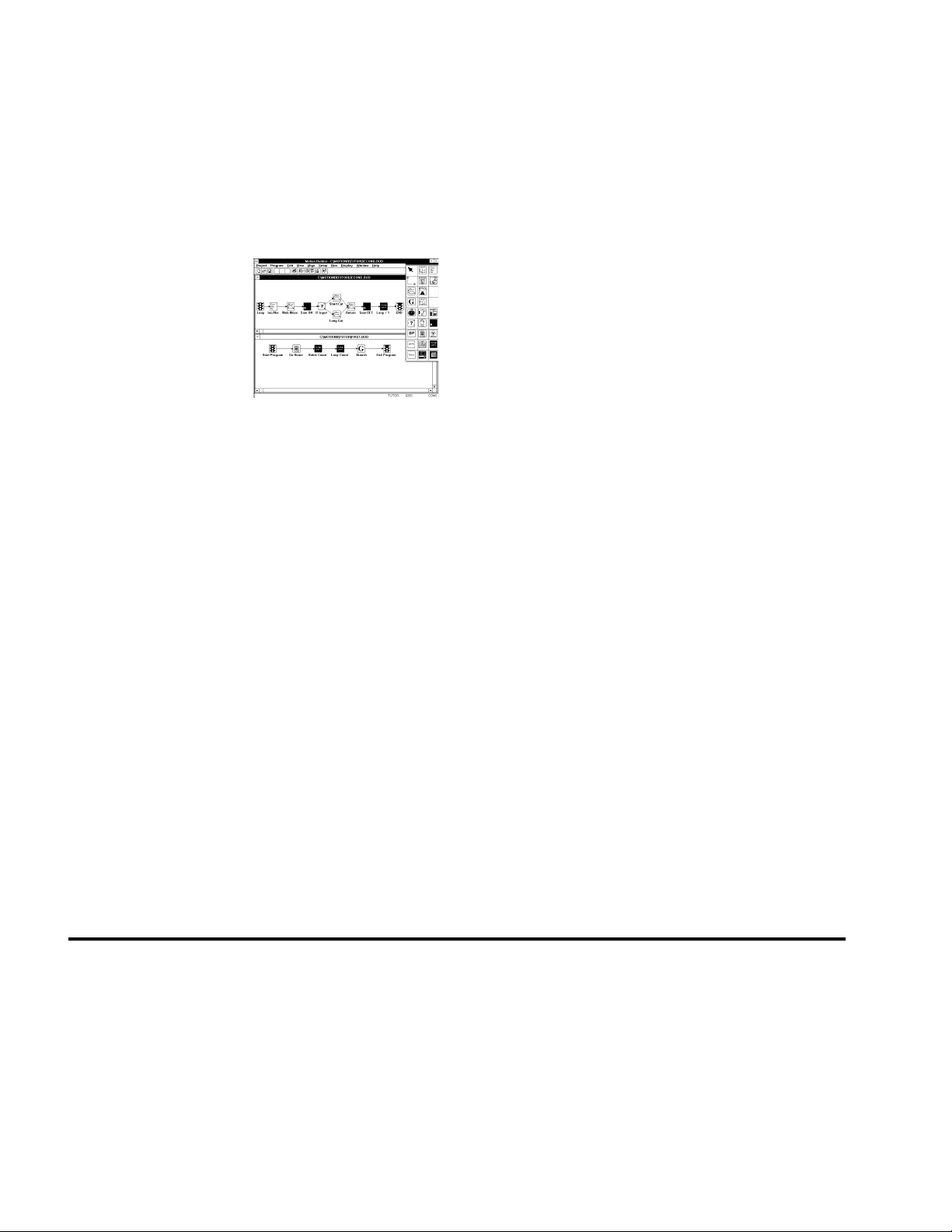
• Motion Builder (graphical icon-based programming software)
• Motion Toolbox (Motion VIs for LabVIEW)
• DOS Support Software
Motion Architect
®
All 6000 Series products are shipped with Motion Architect, an intuitive Microsoft® Windows™
based programming tool. A brief description of Motion Architect's basic features is provided
below. For more detailed user information, refer to the Motion Architect User Guide.
• System Configurator and Code Generator: Automatically generate controller
code of basic system set-up parameters (I/O definitions, feedback device operations, etc.).
• Program Editor: Create blocks or lines of 6000 controller code, or copy portions of
code from previous files. You can save program editor files for later use in BASIC, C,
etc., or in the terminal emulator or test panel.
• Terminal Emulator: Communicating directly with the 6000 controller, the terminal
emulator allows you to type in and execute controller code, transfer code files to and from
the 6000 product. If you are using a bus-based 6000 controller, you can use this module
to transfer (download) the soft operating system.
• Test Panel and Program Tester: You can create your own test panel to run your
programs and check the activity of I/O, motion, system status, etc. This can be invaluable
during start-ups and when fine tuning machine performance.
• On-line Context-sensitive Help and Command Reference: These on-line
resources provide help information about Motion Architect, as well as interactive access
to the contents of the 6000 Series Programmer's Guide (this document) and the
6000 Series Software Reference.
• Dynamic Link Libraries: DLL device drivers are provided for bus-based controller
customers who wish to create a Windows-based application to interface with the controller.
Overview
iii
Page 15
Add-On
Modules
Motion Builder™
Motion Toolbox™
Add-on modules for Motion Architect are available to aide in other programming and setup
tasks. These modules are available from your local Automation Technology Center (ATC) or
distributor. For detailed user information, please refer to the respective user guide.
• Servo Tuner™ (Tuning and Data Gathering Tool): Tune the servo drives and the 6000
servo controller and receive instant data feedback on customizable displays.
• CompuCAM™: CAD-to-Motion (CAM) software allows you to translate DXF,
HP-GL, and G-Code files into 6000 Series Language motion programs.
Motion Builder, a Microsoft Windows-based iconic
programming environment, allows expert and novice
programmers to easily program Compumotor’s 6000 Series
products without learning a new programming language or
syntax. Use Motion Builder to completely configure the
motion controller; program the motion with drag-and-drop
visual icons; compile, run and debug the program.
Motion Toolbox is a library of LabVIEW® virtual instruments (VIs) for Compumotor's 6000
Series controllers. Motion Toolbox allows LabVIEW programmers to develop motion
control systems for a wide range of applications including automated test and manufacturing,
medical and biotech, metering and dispensing, machine control, and laboratory automation.
Motion Toolbox provides developers with these capabilities:
• Motion control, including velocity, acceleration, deceleration, go, stop, kill, etc.
• Setup, control, and command file transfer
• Counter and timer configuration and control
• Indexer, encoder, and drive configuration
• Home, hardware limit, and soft limit configuration
• Jogging and joystick configuration
• I/O setup and function configuration
• Fast status querying of I/O, limit, home, motor and encoder position, velocity, etc.
DOS Support Software
In addition to Motion Architect, support software written for the DOS environment is
available for all 6000 Series products.
Details about these
software tools are
provided in Chapter 2,
Communication
.
The 6000 DOS Support Disk, which provides a program for terminal emulation and program
editing for serial (“stand-alone”) products, is available from your local ATC or distributor.
Bus-based products are shipped with a DOS support disk (see diskette labeled with the
product's name) that includes the soft operating system (.OPS file) and programs that
demonstrate how to communicate with the 6000 product.
Technical Support
For solutions to your questions about implementing 6000 product software features, first look
in this manual. Other aspects of the product (command descriptions, hardware specs, I/O
connections, graphical user interfaces, etc.) are discussed in the respective manuals listed above
in Reference Documentation (see page ii).
iv
If you cannot find the answer in this documentation, contact your local Automation
Technology Center (ATC) or distributor for assistance.
If you need to talk to our in-house application engineers, please contact us at the numbers
listed on the inside cover of this manual. (The phone numbers are also provided when you
issue the HELP command to the 6000 controller.)
6000 Series Programmer's Guide
Page 16

CHAPTER ONE
Programming
Fundamentals
1
IN THIS CHAPTER
This chapter is a guide to general 6000 programming tasks. It is divided into these main topics:
• Motion Architect programming environment .............. 2 • Restricted commands during motion .................... 18
• Command syntax ................................................. 3 • Using Variables............................................. 18
• Creating programs (program development scenario) ...... 8 • Program flow control ...................................... 23
• Storing programs................................................. 12 • Program interrupts.......................................... 29
• Executing programs .............................................. 14 • Error handling............................................... 30
• Creating and executing a set-up program..................... 1 4 • Non-volatile memory (stand-alone products) ......... 33
• Program Security.................................................. 1 5 • System performance considerations .................... 33
• Controlling execution – programs & command buffer .... 16
Page 17

Motion & Control
Motion Architect Programming Environment
Every 6000 Series controller is shipped with Motion Architect, a Windows-based
programming tool designed to simplify your programming efforts. The main features of
Motion Architect are briefly described below. For detailed user information, refer to the
Motion Architect User Guide.
• Setup Module: Provides dialog boxes for you to select basic system setup parameters
(I/O definitions, position feedback, etc.) and then automatically generates a fullycommented “setup program.”
• Editor Module : Create blocks or lines of 6000 controller code, or copy portions of
code from previous files. You can save program editor files for later use in BASIC, C,
etc., or in the terminal emulator or test panel.
• Terminal Module: Communicating directly with the 6000 controller, the terminal
emulator allows you to type in and execute controller code and transfer code files to and
from the 6000 controller.
• Panel Module: You can create your own test panel to run your programs and check
the activity of I/O, motion, system status, etc. This can be invaluable during start-ups
and when fine tuning machine performance.
• On-line Help and User Documentation: Under the Help menu, you will find
user information about Motion Architect, as well as interactive access to the contents of
the 6000 Series Programmer's Guide (the document you are reading right now)
and the 6000 Series Command Reference.
Add-on modules for Motion Architect are available to aide in other programming and set-up
tasks. These modules are available through your local Automation Technology Center.
• Servo Tuner™: Tune your servo controller and the attached servo drives and receive
instant data feedback on customizable displays. For detailed user information, refer to the
Servo Tuner User Guide.
• CompuCAM™: CompuCAM allows you to import 2D geometry from CAD
programs (DXF), plotter files (HP-GL), or NC programs (G-Code), and then translate the
geometry into 6000 motion programs. These programs can be further edited in Motion
Architect's Program Editor module and dowloaded to the 6000 controller from the
Terminal Emulator or Test Panel modules. A typical use of CompuCAM is to automate
the process for developing 6000 Series contouring code for an application. For detailed
user information, refer to the CompuCAM User Guide.
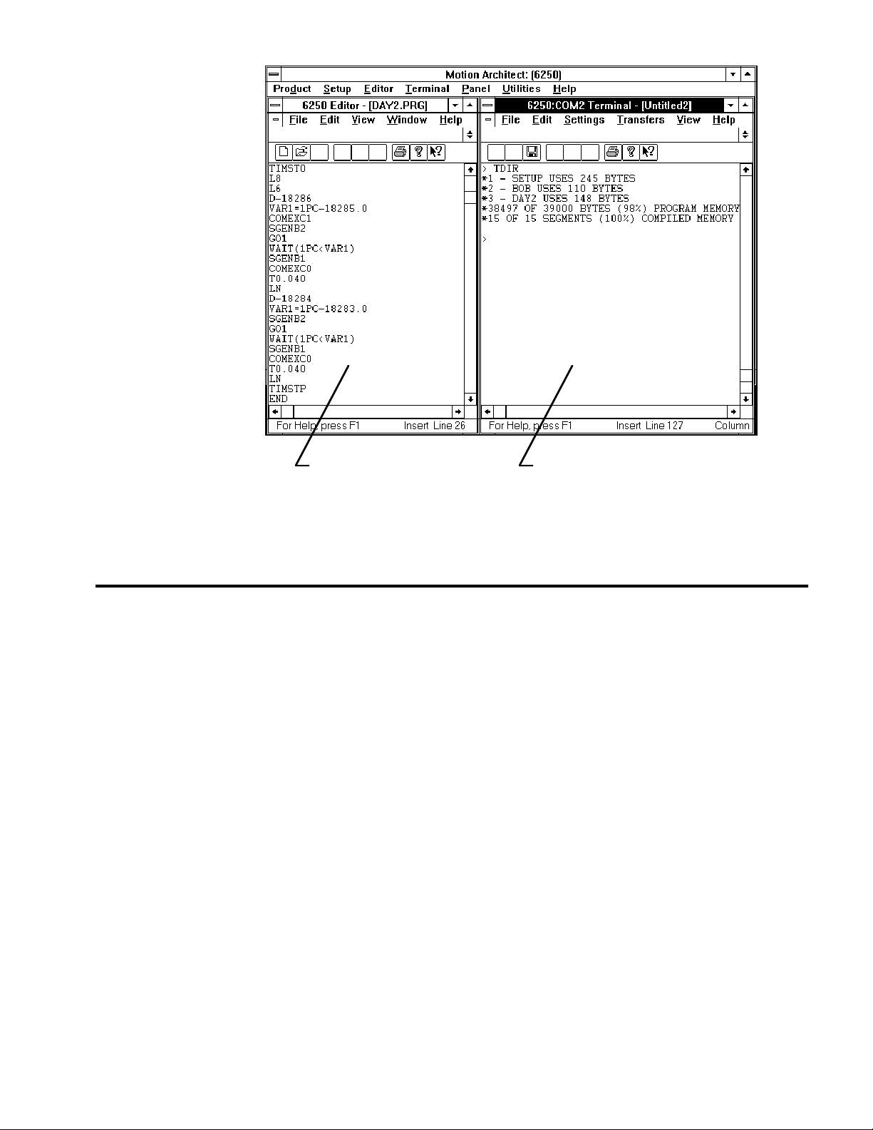
Side-by-Side Editor and Terminal Windows
Typically, the programming process is an iterative exercise in which you create a program,
This side-by-side
technique is
demonstrated in the
programming
scenario on page 8.
2
6000 Series Programmer's Guide
test it, edit it, test it ... until you are satisfied with the results. To help with this iterative
process, we suggest using Motion Architect's Editor and Terminal modules in a side-by-side
fashion (open an Editor session and a Terminal session and re-size the windows so that you
can see both at the same time). In doing so you can quickly jump back and forth between
editing a program (Editor function) and downloading it to the product and checking
programming responses and error messages (Terminal functions).
(see illustration below)
Page 18
Command Syntax
Overview
The 6000 Series language provides high-level constructs as well as basic motion control
building blocks. The language comprises simple ASCII mnemonic commands, with each
command separated by a command delimiter. Upon receiving a command followed by a
command delimiter, the 6000 controller places the command in its internal command queue.
Here the command is executed in the order in which it is received. The command may be
specified as immediate by placing an optional exclamation point (!) in front of the command.
When a command is specified as an immediate command, it is placed at the front of the
command queue, where it is executed immediately.
The command delimiter can be one of three characters, a carriage return, a line-feed, or a colon
(:). Spaces and tabs within a command are processed as neutral characters. Comments can be
specified with the semicolon (;) character — all characters following the semicolon until the
command delimiter are considered program comments.
There is no case sensitivity with the command language. For instance, the command TSTAT
is the same as the command tstat.
Program Editor: Create and edit
programs, save them, and then
download them from the Terminal
module.
Terminal Emulator: Communicate directly with the
6000 controller. Download files containing
stand-alone commands and/or complete programs
or subroutines. Check system responses. Upload
programs from the 6000 controller.
Some commands contain one or more data fields in which you can enter numeric or binary
values or text. The A command (syntax: A<r>,<r>,<r>,<r>) is an example of a
command that requires you to enter numeric values (e.g., the A5,6,7,8 command assigns
acceleration values of 5, 6, 7, and 8 units/sec2 to axes #1, #2, #3, and #4 respectively). The
DRIVE command (syntax: DRIVE<b><b><b><b>) is an example of a command that
requires binary values (e.g., the DRIVE11ØØ command enables drives #1 and #2 and disables
drives #3 and #4). The STARTP command (syntax: STARTP<t>) is an example of a
command that requires text (e.g., the STARTP powrup command assigns the program called
“powrup” as the start-up program).
Chapter 1. Programming Fundamentals
3
Page 19

Description of Syntax Letters and Symbols
The command descriptions provided within the 6000 Series Software Reference use
alphabetic letters and ASCII symbols within the Syntax description to represent different
parameter requirements (see example below).
INEN Input Enable
Type Inputs or Program Debug Tools
Syntax Symbology
☞
Syntax <!>INEN<d><d><d>...<d>>
Units d = Ø, 1, E, or X
Range Ø = off, 1 = on, E = enable, X = don't change
Default E
Response INEN: *INENEEEE_EEEE_EEEE_EEEE_EEEE_EEEE_EEEE
See Also [ IN ], INFEN, INFNC, INLVL, INPLC, INSTW, TIN
Letter /
Symbol Description
Product Rev
AT6n00 1.0
AT6n50 1.0
610n 1.0
615n 1.0
620n 1.0
625n 1.0
6270 1.0
a Represents an axis specifier, numeric value from 1 to 4 (used only to elicit a
b
c Represents a character (A to Z, or a to z)
d Represents the values 1,Ø, X or x, E or e ; does not require field separator
i Represents a numeric value that cannot contain a decimal point (integer values
r Represents a numeric value that may contain a decimal point, but is not required
t Represents a string of alpha numeric characters from 1 to 6 characters in length.
! Represents an immediate command. Changes a buffered command to an
, Represents a field separator. Commands with the symbol r or i in their Synt ax
response from the indexer)
*
Represents the values 1,Ø, X or x; does not require field separator between
values.
between values. E or e enables a specific command field. X or x leaves the
specific command field unchanged or ignored.
only). The numeric range varies by command. Field separator (,) required.
to have a decimal point. The numeric range varies by command. Field separator
(,) required.
The string must start with an alpha character.
immediate command. Immediate commands are processed immediately, even
before previously entered buffered commands.
description require field separators. Commands with the symbol b or d in their
Synt ax description do not require field separators (but they may be included).
See
General Guidelines
table below for more information.
@ Represents a global specifier, where only one field need be entered. Applicable
< > Indicates that the item contained within the < > is optional, not required by that
[ ] Indicates that the command between the [ ] must be used within the syntax of
*
The ASCII character b can also be used within a command to precede a binary number. When the b is
used in this context, it is not to be replaced with a Ø, 1, X, or x. Examples are assignments such as
VARB1=b1ØØØ1, and comparisons such as IF(IN=b1ØØ1X1).
4
6000 Series Programmer's Guide
to all commands with multiple command fields. (e.g., @V1 sets velocity on all
axes to 1 rps)
command. NOTE: Do not confuse with <cr>, <sp>, and <lf>, which refer to the
ASCII characters corresponding to a carriage return, space, and line feed,
respectively.
another command, and cannot be used by itself.
Page 20

General Guidelines for Syntax
Topic Guideline Examples *
Neutral Characters:
• Space (
• Tab (
Command Delimiters:
• Carriage rtn (
• Line feed (
• Colon (:)
Comment Delimiter (;) All text between a comment delimiter and a
Field Separator (,) Commands with the symbol r or i in their
<sp>
<tab>
)
)
<cr>
<lf>
Using neutral characters anywhere within a
command will not affect the command.
(In the examples on the right, a space is
represented by
carriage return is
All commands must be separated by a
)
command delimiter. A carriage return is the
)
most commonly used delimiter. To use a line in
a live terminal emulator session, press ctrl/J.
The colon (:) delimiter allows you to place
multiple commands on one line of code, but
only if you add it in the program editor (not
during a live terminal emulator session).
command delimiter is considered
comments
Synt ax description require field separators.
Commands with the symbol b or d in their
Synt ax description do not require field
separators (but they may be included).
Axes not participating in the command need
not be specified; however, field separators
that are normally required must be specified.
<sp>
, a tab is
<cr>
.)
.
<tab>)
program
, and a
Set velocity on axis 1 to 10 rps and axis 2 to 25 rps:
V
<sp>
1Ø,
<sp>
25,,
<cr>
Add a comment to the command:
V 1Ø, 25,,
Set acceleration on axis 2 to 10 rps
A,1Ø,,
A,1Ø,,
A,1Ø,, : V,25,, : D,25ØØØ,, : @GO
Add a comment to the command:
V1Ø<tab> ;set velocity
Set velocity on axes 1-4 to 10, 25, 5 and 10 rps,
respectively:
V1Ø,25,5,1Ø
Initiate motion on axes 1, 3 and 4:
GO1Ø11
GO1,Ø,1,1
Set velocity on axis 2 to 5 rps:
V,5,,
<cr>
<lf>
<cr>
<cr>
<tab>
;set accel
<cr>
<cr>
2
:
<cr>
<cr>
<cr>
Global Command
Identifier (@)
Bit Select Operator (.) The bit select operator allows you to affect
Case Sensitivity There is no case sensitivity. Use upper or
Left-to-right Math All mathematical operations assume left-to-
* Non-visible characters are represented: space =
NOTE: The command line is limited to 80 characters (excluding spaces).
When you wish to set the command value
equal on all axes, add the @ symbol at the
beginning of the command (enter only the
value for one command field).
one binary bit without having to enter all the
preceding bits in the command.
Syntax for setup commands:
[command name].[bit #]-[binary value]
Syntax for conditional expressions:
[command name].[bit #]=[binary value]
lower case letters within commands.
right precedence.
<sp>
, tab =
<tab>
, carriage return (or enter key) =
Set velocity on all axes to 10 rps:
@V1Ø
<cr>
Enable error-checking bit #9:
ERROR.9-1
IF statement based on value of axis status bit #12:
IF(1AS.12=b1)
Initiate motion on axes 1, 3 and 4:
GO1Ø11
go1Ø11
VAR1=5+3*2
Result: Variable 1 is assigned the value of 16
(8*2), not 11 (5+6).
<cr>
<cr>
<cr>
<cr>
<cr>
<cr>
, line feed =
<lf>
.
Chapter 1. Programming Fundamentals
5
Page 21

Command Value Substitutions
Many commands can substitute one or more of its command field values with one of these
substitution items (demonstrated in the programming example below):
VARB...... Uses the value of the binary variable to establish all the command fields.
VAR ....... Places current value of the numeric variable in the corresponding command field.
READ...... Information is requested at the time the command is executed.
DREAD.... Reads the RP240's numeric keypad into the corresponding command field.
DREADF .. Reads the RP240's function keypad into the corresponding command field.
TW ......... Places the current value set on the thumbwheels in the corresponding command field.
DAT ....... Places the current value of the data program (DATP) in the corresponding command field.
Programming Example: (NOTE: The substitution item must be enclosed in parentheses.)
VAR1=15 ; Set variable 1 to 15
A5,(VAR1),4,4 ; Set acceleration to 5,15,4,4 for axes 1-4, respectively
VARB1=b1101XX1 ; Set binary variable 1 to 1101XX1 (bits 5 & 6 not affected)
GO(VARB1) ; Initiate motion on axes 1, 2 & 4 (value of binary
; variable 1 makes it equivalent to the GO1101 command)
OUT(VARB1) ; Turn on outputs 1, 2, 4, and 7
VARS1="Enter Velocity" ; Set string variable 1 to the message "Enter Velocity"
V2,(READ1) ; Set the velocity to 2 on axis 1. Read in the velocity for
; axis 2, output variable string 1 as the prompting message
; 1. Operator sees "ENTER VELOCITY" displayed on the screen.
; 2. Operator enters velocity prefixed by !' (e.g., !'20).
HOMV2,1,(TW1) ; Set homing velocity to 2 and 1 on axes 1 and 2, respectively.
; Read in the home velocity for axis 3 from thumbwheel set 1
HOMV2,1,(DAT1) ; Set homing velocity to 2 and 1 on axes 1 and 2, respectively.
; Read home velocity for axis 3 from data program 1.
Not all of the commands allow command field substitutions. In general, commands with a
binary command field (<b> in the command syntax) will accept the VARB substitution.
Commands with a real or integer command field (<r> or <i> in the command syntax) will
accept VAR, READ, DREAD, DREADF, TW or DAT.
Assignment and Comparison Operators
Comparison and assignment operators are used in command arguments for various functions
such as variable assignments, conditional branches, wait statements, conditional GOs, etc.
Some examples are listed below:
• Assign to numeric variable #6 the value of the encoder position on axis #3 (uses the PE
operator): VAR6=3PE
• Wait until inputs #3 & #6 become active (uses the IN operator): WAIT(IN=bxx1xx1)
• Continue until the value of numeric variable #2 is less than 36: UNTIL(VAR2<36)
• IF condition based on if a target zone timeout occurs on axis 2 (uses the AS axis status
operator, where status bit #25 is set if a target zone timeout occurs): IF(2AS.25=b1)
The available comparison and assignment operators are listed below. For full descriptions,
refer to their respective descriptions in the 6000 Series Software Reference
(be sure to refer only to the commands in brackets—e.g., A is the acceleration setup command,
but [ A ] is the acceleration assignment/comparison operator).
RULE OF THUMB
6
6000 Series Programmer's Guide
Page 22

* denotes operators that
have a correlated status
display command.
(e.g., To see a full-text
description of each axis
status bit accessed with
the AS operator, send
the TASF command to
the 6000 controller.)
See page 232.
A........... Acceleration
AD ......... Deceleration
ANI........ Voltage at the ANI analog inputs (servos with ANI option) *
ANV........ Voltage at the joystick analog channels *
AS ......... Axis status *
ASX........ Extended axis status (additional axis status items) *
CA ......... Captured ANI analog input voltage *
CNT........ Counter value (steppers only) *
D........... Distance
DAC........ Digital-to-analog converter (output voltage) value (servos only) *
DAT........ Data program number
DPTR...... Data pointer location *
DREAD .... Data from the numeric keypad on the RP240 (stand-alone products only)
DREADF... Data from the function keypad on the RP240 (stand-alone products only)
ER ......... Error status *
FB ......... Position of current selected feedback sources *
FS ......... Following status *
IN ......... Input status (input bit patterns provided in Chapter 3, page 107) *
INO........ “Other” input status (joystick inputs, and P-CUT or ENBL input) *
LDT........ Position of the LDT (hydraulic servos only) *
LIM........ Limit status (end-of-travel limits and home limits) *
MOV........ Axis moving status
NMCY...... Current master cycle number *
OUT........ Output status (output bit patterns provided in Chapter 3, page 107) *
PANI...... Position of ANI analog input, at 819 counts/volts unless otherwise scaled (servos) *
PC ......... Commanded position (servos only) *
PCA........ Captured ANI input position (servos with ANI option only) *
PCC........ Captured commanded position (servos only) *
PCE........ Captured encoder position *
PCL........ Captured LDT position (hydraulic servos only) *
PCM........ Captured motor position (steppers only) *
PE ......... Position of encoder *
PER........ Position error (n/a to OEM-AT6400) *
PM ......... Position of motor (steppers only) *
PMAS...... Current master cycle position *
PSHF...... Net position shift since constant following ratio *
PSLV...... Current commanded position of the slave axis *
READ...... Read a numeric value to a numeric variable (VAR)
SEG........ Number of segments available in Compiled Profile memory *
SS ......... System status *
TIM........ Timer value *
TW ......... Thumbwheel data read
US ......... User status *
V........... Velocity (programmed)
VAR........ Numeric variable substitution
VARB...... Binary variable substitution
VEL........ Velocity (commanded by the controller) *
VELA...... Velocity (actual, as measured by a position feedback device) *
VMAS...... Current velocity of the master axis *
Bit Select
Operator
Binary and Hex
Values
The bit select operator (.) makes it easier to base a command argument on the condition of one
specific status bit. For example, if you wish to base an IF statement on the condition that a
user fault input is activated (error status bit #7 is a binary status bit that is “1” if a user fault
occurred and “Ø” if it has not occurred), you could use this command: IF(ER=bxxxxxx1).
Using a bit select operator, you could instead use this command: IF(ER.7=b1).
Side Note: You can use a bit select operator to set a particular status bit (e.g., to turn on
programmable output #5, you would type the OUT.5-1 command; to enable error-checking
bit #4 to check for drive faults, you would type the ERROR.4-1 command). You can also
check specific status bits (e.g., to check axis 2's axis status bit #25 to see if a target zone
timeout occurred, type the 2TAS.25 command and observe the response).
When making assignments with or comparisons against binary or hexadecimal values, you
must precede the binary value with the letter “b” or “B”, and the hex value with “h” or “H”.
Examples: IF(IN=b1xØ1) and IF(IN=h7F). In the binary syntax, an “x’ simply means
the status of that bit is ignored. Refer also to Using Binary Variables (page 22).
Chapter 1. Programming Fundamentals
7
Page 23

Related
Operator
Symbols
Command arguments include special operator symbols (e.g., +, /, &, ', >=, etc.) to perform
bitwise, mathematical, relational, logical, and other special functions. These operators are
described in detail, along with programming examples, at the beginning of the Command
Descriptions section of the 6000 Series Software Reference.
Programmable Inputs and Outputs Bit Patterns
The total number of inputs and outputs (I/O) varies from one 6000 Series product to another.
I/O pin outs,
specifications, and
circuit drawings are
provided in each 6000
Series product's
installation guide.
Consequently, bit patterns for the programmable I/O also vary by product. For example, the
AT6400's TRG-A trigger input is represented by programmable input bit #25, but the 6104's
TRG-A trigger input is bit #17. Bit numbers are referenced in commands like
WAIT(IN.13=b1), which means wait until programmable input #13 becomes active. To
ascertain your product's I/O offering and bit patterns, refer to Chapter 3 (page 107).
Creating Programs
A program is a series of commands. These commands are executed in the order in which they
are programmed. Immediate commands (commands that begin with an exclamation point [!])
cannot be stored in a program. Only buffered commands may be used in a program.
Debugging Programs:
Refer to page 231 for
methods to isolate and
resolve programming
problems.
A subroutine is defined the same as a program, but it is executed with an unconditional branch
command, such as GOSUB, GOTO, or JUMP, from another program (see page 23 for details
about unconditional branching). Subroutines can be nested up to 16 levels deep. NOTE: The
6000 family does not support recursive calling of subroutines.
Another kind of program is a compiled profile. Compiled profiles are defined like programs
(using the DEF and END commands), but are compiled with the PCOMP command and executed
with the PRUN command. A compiled profile could be a multi-axis contour (a series of arcs
and lines), an individual axis profile (a series of GOBUF commands), or a compound profile
(combination of multi-axis contours and individual axis profiles). For more information on
contours, refer to Contouring in Chapter 5, page 153. For more information on compiled
individual axis profiles, refer to Compiled Motion Profiling in Chapter 5, page 163.
Program Development Scenario
To best understand the process of developing 6000 programs, we invite you to follow along
on a program development scenario. The scenario covers these programming tasks:
1. Set up the programming environment (using Motion Architect's Editor and Terminal).
2. Create a simple motion program in the Editor.
3. Download the program, via the Terminal, to the controller.
4. Execute (run) the program from the Terminal.
5. Edit the program, redownload it, and run it again.
1. Set up Motion
Architect.
Typically, the programming process is an iterative exercise in which you create a program,
test it, edit it, test it ... until you are satisfied with the results. To help with this iterative
process, we suggest using Motion Architect's Editor and Terminal modules in a side-by-side
fashion (open an Editor session and a Terminal session and re-size the windows so that you
can see both at the same time). In doing so you can quickly jump back and forth between
editing a program (Editor function) and downloading it to the product and checking
programming responses and error messages (Terminal functions).
8
6000 Series Programmer's Guide
Page 24
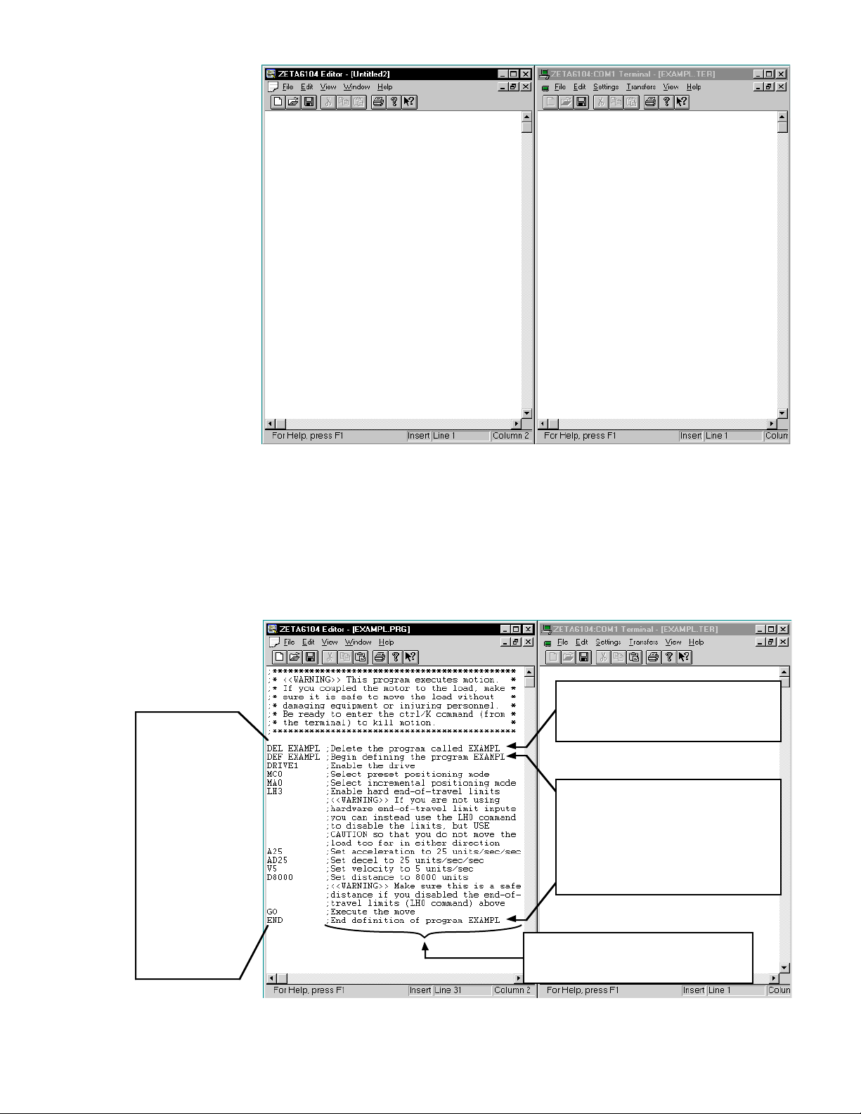
Program Editor
1. Create program file(s) and save to disk.
2. Download files via the terminal emulator.
3. Repeat steps 1 & 2 to edit the code.
Terminal Emulator
• Communicate directly with the controller.
• Download files containing complete 6000
programs or stand-alone 6000 commands.
• Check system status responses.
• Upload programs from the controller to disk.
2. Define a program. Type in the commands as shown in the Editor window below. The Editor window also shows
program comments to help you understand the purpose of each command and the implications
of executing motion. Notice that the comments are placed after the comment delimiter (;).
NOTE: This is a programming example for single-axis motion. When programming
multiple axes, you would use the additional command fields. For example, the command for
setting the acceleration on axes one and two to 12 units/sec2 and axes three and four to 25
units/sec2 would be A12,12,25,25; and setting axes one and two to preset positioning
mode and axes three and four to continuous positioning mode requires the MCØØ11 command.
Use these
commands:
DEL EXAMPL
DEF EXAMPL
DRIVE1
MC0
MA0
LH3
(or LH0)
A25
AD25
V5
D8000
GO
END
The program is deleted (DEL EXAMPL) before it is
defined; this is done to avoid program errors and
unexpected motion when downloading the program
to the controller.
Make a habit of deleting before defining.
Program definition begins with the Begin Program
Definition (DEF) command followed by a program
name of ≤ 6 characters (e.g., DEF EXAMPL).
The End Program Definition (END) command ends
the program definition.
All buffered commands that you enter after DEF
and before END will be executed when the program
is run.
All text between the comment delimiter (;) and the
carriage return are considered “program comments.”
The warning at the beginning of this program file
comprises 8 lines of comments.
Chapter 1. Programming Fundamentals
9
Page 25
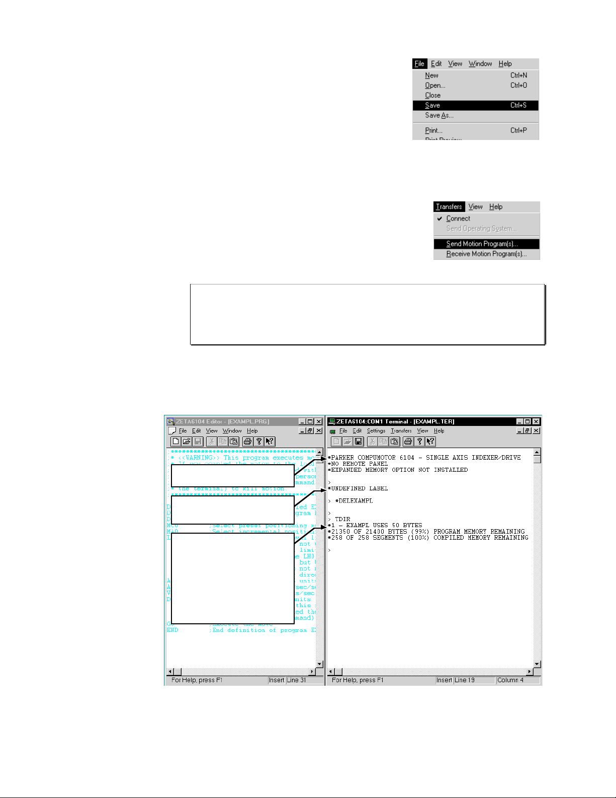
3. Download the
program.
FIRST: Before you can download the program, you
must save it to your hard drive (select File/Save in the
Editor). The file is saved with a “.PRG” extension. In
the Save dialog box, name the file “EXAMPL.PRG”.
Follow these steps to download the program file to the
controller:
1. Power up the controller. Notice the power-up
message (like the one shown below) display in your
terminal emulator window.
Save the program first (Editor).
2. From the Transfers menu in the Terminal window,
Download the program (Terminal).
select Send Motion Program(s). From the dialog box,
select the EXAMPL.PRG file and click OK. The first
time you download the file, you will see two messages
display: “*UNDEFINED LABEL” and ”DELEXAMPL”
(on subsequent downloads of the same file, you would
instead see the message “NO ERRORS”).
TIP: If the controller is executing a program when you try to download a program
file, the program(s) from the program file will not download and the contents of the
program(s) will be displayed to the terminal emulator window. To prevent this error,
“kill” program execution (and motion) before downloading the program file — use
the !K command or the ctrl/K command (ctrl/K is an easier keystroke combination).
3. To verify that the EXAMPL program resides in the controller's memory, type the TDIR
command and press the carriage return or enter key.
Power-up message for the ZETA6104
controller.
10
Messages for first-time download
(subsequent download will yield the
message “NO ERRORS”).
The TDIR status command yields a
3-line response. The first line shows
the the EXAMPL program resides in
memory and uses 50 bytes. The
second line shows the status of
memory available for program
storage (this is where EXAMPL is
stored). The third line shows the
status of memory available to store
compiled motion profiles (programs
compiled with the PCOMP command).
6000 Series Programmer's Guide
Page 26
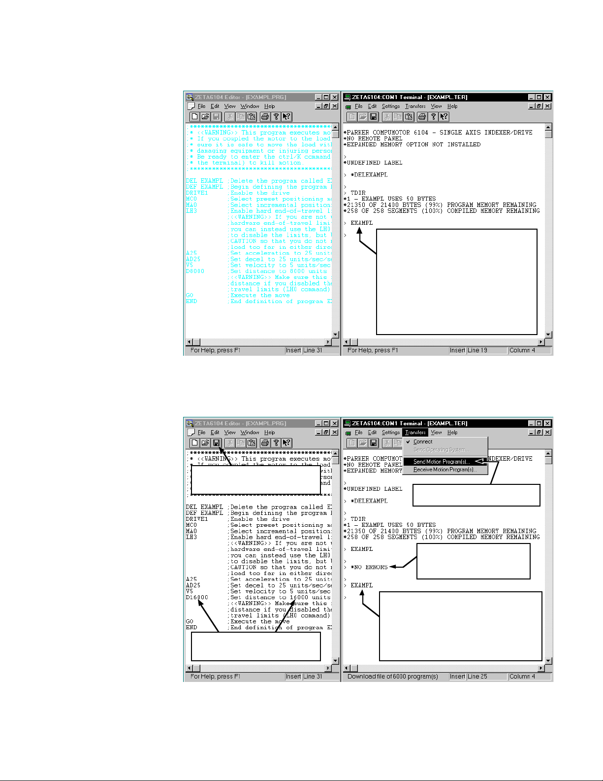
4. Run the program.
Other methods of
executing programs are
listed in
Executing
Programs
(page 14).
WARNING: Executing this program will cause motion. If you coupled the motor(s)
to the load, make sure it is safe to move the load without damaging equipment or injuring
personnel.
To run the program from the terminal emulator, type
the name of the program (in this case it is EXAMPL)
and press the carriage return or enter key.
If you are using a stepper, the default resolution will
most likely be set to 25,000 steps per rev; therefore,
running the EXAMPL program should move the motor
about 1/3 rev.
If you are using a servo, the default resolution will
most likely be set to 4,000 counts per rev; therefore,
running the EXAMPL program should move the motor
about 2 revs.
5. Edit the program. To demonstrate the iterative nature of programming, let’s change distance of the move in the
EXAMPL program, redownload the EXAMPL.PRG file, and run the EXAMPL program.
Click this toolbar button to save the
➁
EXAMPL.PRG file before
downloading it to the controller.
Double the distance (D) command
➀
value from 8000 units to 16000 units
(change the comment as well).
Enter the name of the program (EXAMPL) to run
➃
the program and execute motion.
If you are using a stepper with default resolution
settings, the motor should move about 2/3 rev.
If you are using a servo with default resolution
settings, the motor should move about 4 revs.
Send (download) the EXAMPL.PRG
➂
program file to the controller.
Message indicates successful
download, overwriting the previous
version of the EXAMPL program that
exists in the controller's memory.
Chapter 1. Programming Fundamentals
11
Page 27
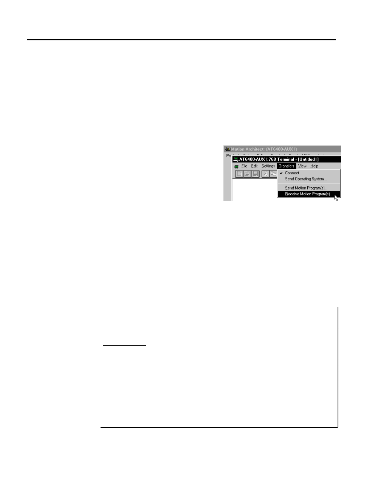
Storing Programs
Programs and compiled profiles are stored in the controller's memory (non-volatile memory
for stand-alone products and volatile memory for bus-based products). Information on
controlling memory allocation is provided below (see Memory Allocation).
Storing Programs in Stand-Alone Products
If you are using a stand-alone (serial interface) product, programs and compiled profiles are
automatically stored in non-volatile memory (battery-backed RAM).
More information on other items that are stored in non-volatile memory is provided below.
Storing Programs in Bus-Based Products
If you are using a bus-based product, programs
and compiled profiles are stored in volatile
RAM memory (not battery-backed). Therefore,
you should backup your motion
programs to your computer's hard disk or
floppy disk to ensure their safety. This is
easily done with the Receive Motion Program
function of Motion Architect's Terminal
Emulator module (see diagram at right).
Memory Allocation
In general, your programs may already be stored on your computer, since most programs are
created with Motion Architect's Editor or with the 6000 DOS support software package (see
Program Development Scenario starting on page 8).
Application set-up parameters such as drive setup, feedback setup, I/O configuration, etc.,
should be placed in a set-up program that is called/downloaded and executed before performing
any other controller functions (see Creating and Executing a Set-Up Program on page 14).
Your controller's memory has two partitions: one for storing programs and one for storing
compiled profiles. The allocation of memory to these two areas is controlled with the
MEMORY command.
“Programs” vs. ”Compiled Profiles”
Programs are defined with the DEF and END commands, as demonstrated in the
Development Scenario
Compiled Profiles are defined like programs (using the DEF and END commands), but are
compiled with the PCOMP command and executed with the PRUN command. A
compiled profile could be a multi-axis
individual axis profile
(combination of multi-axis contours and individual axis profiles).
Programs intended to be compiled are stored in program memory. After they are
compiled with the PCOMP command, they remain in program memory and the
segments
memory. The TDIR command reports which programs are compiled as a compiled
profile (referred to here as a
For more information on multi-axis contours, refer to
153. For more information on compiled profiles for individual axes, refer to
Motion Profiling
(see diagram below) from the compiled profile are stored in compiled
starting on page 8.
contour
(a series of arcs and lines), an
(a series of GOBUF commands), or a
path
).
in Chapter 5, page 163.
compound profile
Contouring
Program
in Chapter 5, page
Compiled
12
6000 Series Programmer's Guide
Page 28
MEMORY
command
syntax
(example)
MEMORY8ØØØØ,7ØØØØ
Memory allocation for Compiled Profiles (bytes).
Storage requirements depend on the number of
segments
in the compiled profile (1 segment consumes
72 bytes). A segment could be one of these commands:
Memory allocation for
Programs (bytes).
Storage requirements
depend on the number of
ASCII characters in the
program.
Contouring: Compiled Motion:
PARCM
PARCOM
PARCOP
PARCP
PLIN
GOBUF
PLOOP
GOWHEN
TRGFN
POUTA
GOBUF commands
may require up to 4
segments.
POUTB
POUTC
POUTD
The following table identifies memory allocation defaults and limits for 6000 Series products.
When specifying the memory allocation, use only even numbers. The minimum storage
capacity for one partition area (program or compiled) is 1,000 bytes.
Feature AT6n00 AT6n00-M AT6n50 AT6n50-M All Other Products
Total memory (bytes) 64000 1500000 40000 150000 150000
Default allocation
(program,compiled)
Maximum allocation for
programs
Maximum allocation for
compiled profiles
Max. # of programs 150 4000 100 40 0 400
Max. # of labels 250 60 00 100 600 600
Max. # of compiled profiles 100 800 100 300 3 00
Max. # of compiled profile
segments
Max. # of numeric
variables
Max. # of string variables 100 100 2 5 25 25
Max. # of binary variables 100 100 2 5 2 5 25
-M refers to the Expanded Memory Option
33000,31000 63000,1000 39000,1000 149000,1000 149000,1000
63000,1000 1499000,1000 39000,1000 149000,1000 149000,1000
1000,63000 1000,1499000 1000,39000 1000,149000 1000,149000
875 20819 541 2069 2069
100 200 150 150 150
When teaching variable data to a data program (DATP), be aware that the memory required for
each data statement of four data points (43 bytes) is taken from the memory allocation for
program storage (see Variable Arrays in Chapter 3, page 120, for details).
Using a memory allocation command (e.g., MEMORY39ØØØ,1ØØØ) will erase all existing
programs and compiled profile segments. However, issuing the MEMORY command without
parameters (i.e., type MEMORY
not affect existing programs or compiled segments.
Checking Memory Status
To find out what programs reside in your controller's memory, and how much of the available
memory is allocated for programs and compiled profile segments, issue the TDIR command (see
example response below). Entering the TMEM command or the MEMORY command (without
parameters) will also report the available memory for programs and compiled profile segments.
Sample response
to TDIR command
*1 - SETUP USES 345 BYTES
*2 - PIKPRT USES 333 BYTES
*32322 OF 33000 BYTES (98%) PROGRAM MEMORY REMAINING
*500 OF 500 SEGMENTS (100%) COMPILED MEMORY REMAINING
Two system status bits (reported with the TSS and SS commands) are available to check when
compiled profile segment storage is 75% full or 100% full. System status bit #29 is set when
segment storage reaches 75% of capacity; bit #30 indicates when segment storage is 100% full.
CAUTION
<cr>
to request the status of how the memory is allocated) will
Chapter 1. Programming Fundamentals
13
Page 29

Executing Programs (options)
Following is a list of the primary options for executing programs stored in your controller:
Method Description See Also
Execute from a terminal
emulator
Execute as a subroutine
from a “main” program
Execute automatically
when the controller is
powered up
Execute a specific program
with BCD weighted inputs
Execute a specific program
with a dedicated input
“Call” from a high-level
program
Execute from an RP240
(remote operator interface)
Execute from your own
custom Windows program
Execute from Motion
Architect's Panel module
Type in the name of the program and press enter. page 11
Use an branch (GOTO, GOSUB, or JUMP) from the main program
to execute another stored program.
Stand-alone products only. Assign a specific program as a startup
program with the STARTP command. When you RESET or cycle
power to the controller, the startup program is automatically
executed.
Define programmable inputs to function as BCD select inputs,
each with a BCD weight. A specific program (identified by its
number) is executed based on the combination of active BCD
inputs. Related commands: INFNCi-B, INSELP, INFEN.
Define a programmable input to execute a specific program (by
number). Related commands: INFNCi-iP, INSELP, INFEN.
Using a programming language such as BASIC or C, write a
program that enables the computer to monitor processes and
orchestrate motion and I/O by executing stored programs (or
individual commands) in the controller.
Execute a stored program from the RUN menu in the RP240's
standard menu system.
Bus-based products only. Use a programming language such as
Visual Basic and the DLLs provided on your Motion Architect disk
to create your own windows application to control the 6000 product.
Use Motion Architect's Panel module to create a test/operator
panel screen to execute programs and monitor the controller's
status (I/O, motion, axis, system, Following, etc.)
page 23
page 14
page 110
page 115
page 143
page 134
page 51
Motion
Architect
User Guide
Creating and Executing a Set-up Program
In most applications, you will benefit by having a set-up, or configuration, program that is
executed before performing any other controller functions. The set-up program contains
various set-up parameters specific to the general operation of your controller. Examples of
these parameters include scaling factors, I/O definitions, feedback device configuration, homing
operations, end-of-travel limits, drive configuration, program execution modes, etc. (more
detail on these features is provided in Chapter 3, Basic Operation Setup, page 77).
Use Motion Architect's Setup module to help you
create the basic configuration program. By simply responding
to a series of dialog boxes, a program is created with a specific
name (as if you created it in the usual process with the DEF
and END commands, as demonstrated on page 9). You can
further edit this program in Motion Architect's Editor module
if you wish. How you execute the set-up program depends on
which product form factor you are using: stand-alone or busbased.
14
6000 Series Programmer's Guide
Page 30

Set-up Program Execution for Stand-Alone Controllers
If you created the set-up program in Motion Architect's Editor, you need to download it to the
6000 controller's non-volatile memory via the Terminal Emulator module (see Send Motion
Program under the Transfers menu). If you created the set-up program in the terminal
emulator, as in the example below, it is already stored to non-volatile memory.
Now that the set-up program is available, you can cause it to be executed automatically after
the 6000 controller is powered-up or reset. To do this, you must assign it as the power-up
start program with the STARTP command (see fourth line in example below).
Example
DEF setup ; Define program setup
TREV ; Report software revision
END ; End of program setup
STARTP setup ; Define program pwrup as the power-up program
RESET ; Reset the controller
; After reset, you should see a message like this:
; *PARKER COMPUMOTOR 6201 MOTION CONTROLLER
; *NO REMOTE PANEL
If the program that is identified as the STARTP program is deleted by the DEL command, the
STARTP is automatically cleared. If you wish to prevent the assigned STARTP program from
being executed, without having to delete the program, issue the STARTP CLR command.
Set-up Program Execution for Bus-Based Controllers
In most cases you will require the parameters in the setup program to be executed as soon as
possible so that subsequent parameters are based on the setup program. This can be done using
Motion Architect. A set up program can be defined (in Motion Architect’s Setup Module),
saved, and then downloaded in the Terminal Module (see Send Motion Program under the
Transfers Menu). Once the setup program has been stored in the controller, it may be run by
issuing the name of the setup program.
An alternative method would be to not store the setup parameters in a setup program, but have
them execute upon downloading to the controller. This can be done be defining the setup
parameters in the Setup Module of Motion Architect, but not specifying a setup program.
This will remove the DEF and END statements from the setup file, which you will download
the same way in Motion Architect’s Terminal Module. Because the statements execute upon
downloading, there is no need to issue a program name.
Program Security
Issuing the INFNCi-Q command enables the Program Security feature and assigns the
Program Access function to the specified programmable input. The “i” represents the number
of the programmable input to which you wish to assign the function.
The program security feature denies you access to the DEF, DEL, ERASE, MEMORY, and
INFNC commands until you activate the program access input. Being denied access to these
commands effectively restricts altering the user memory allocation. If you try to use these
commands when program security is active (program access input is not activated), you will
receive the error message *ACCESS DENIED.
For example, once you issue the INFNC22-Q command, input #22 is assigned the program
access function and access to the DEF, DEL, ERASE, MEMORY, and INFNC commands will
be denied until you activate input #22.
To regain access to these commands without the use of the program access input, you must
issue the INFENØ command to disable programmable input functions, make the required user
memory changes, and then issue the INFEN1 command to re-enable the programmable input
functions.
Chapter 1. Programming Fundamentals
15
Page 31

Controlling Execution of Programs and the Command Buffer
The 6000 controller command buffer is capable of storing 2000 characters waiting to be
processed. (This is separate from the memory allocated for program storage – see Memory
Allocation, page 12.) Three commands, COMEXC, COMEXK, and COMEXP, affect command
execution. Three additional commands, COMEXL, COMEXR, and COMEXS, affect the
execution of programs and the command buffer.
COMEXC (Continuous Command Execution)
The COMEXC command enables the Continuous Command Execution Mode. This mode
allows the program to continue to the next command before motion is complete. This is
useful for:
• Monitoring other processes while motion is occurring
• Performing calculations in advance of motion completion
• Pre-emptive GOs — executing a new profile with new attributes (distance, accel/decel,
velocity, positioning mode, and Following ratio ) before motion is complete: The
motion profile underway is pre-empted with a new profile when a new GO is issued. The
new GO both constructs and launches the pre-empting profile. Pre-emptive GOs are
appropriate when the desired motion parameters are not known until motion is already
underway. For a detailed description, refer to On-The-Fly Motion on page 178.
• Pre-process the next move while the current move is in progress (see CAUTION note).
This reduces the processing time for the subsequent move to only a few microseconds.
CAUTION: Avoid executing moves prematurely
With continuous command execution enabled (COMEXC1), if you wish motion to stop
before executing the subsequent move, place a WAIT(AS.1=bØ) statement before the
subsequent GO command. If you wish to ensure the load settles adequately before the
next move, use the WAIT(AS.24=b1) command instead (this requires you to define
end-of-move settling criteria — see
In the programming example below, by enabling the continuous command execution mode
(COMEXC1), the controller is able to turn on output #3 after the encoder moves 4000 units of
its 125000-unit move. Normally, with COMEXC disabled (COMEXCØ), command processing
would be temporarily stopped at the GO1 command until motion is complete.
Programming Example (portion of program only)
COMEXC1 ;Enable continuous command execution mode
D125000 ;Set distance
V2 ;Set velocity
A10 ;Set acceleration
GO1 ;Initiate motion on axis 1
WAIT(1PE>4000) ;Wait for the encoder position to exceed 4000
OUTXX1 ;Turn on programmable output #3
WAIT(AS.1=b0) ;Wait for motion to complete on axis 1 (AS bit #1 = zero)
OUTXX0 ;Turn off programmable output #3
COMEXK (Continue Command Execution on Kill)
This feature is applicable only to bus-based products. The COMEXK command
determines whether the commands following a Kill (K) command in a block write will be saved
after the (K) command is processed. Upon receiving a (K) command, or an external kill input
(INFNCi-C), all commands in the command buffer are eliminated. If there are any other
commands contained within the data block during the Kill (K) command, these commands will
also be eliminated from the command buffer, unless Continue Execution on Kill (COMEXK) is
enabled. This also holds true when a Kill input is received.
Target Zone Mode
on page 105 for details).
16
6000 Series Programmer's Guide
Page 32

COMEXL (Save Command Buffer on Limit)
The COMEXL command enables saving the command buffer and maintaining program
execution when a hardware or software end-of-travel limit is encountered. For more
information on end-of-travel limits, refer to page 90.
COMEXP (Pause Command Execution Until In Position Signal)
This feature is applicable only to stepper products, excluding the OEM-AT6400, 6104 and
6201. The COMEXP command enables waiting for the in-position signal (DRIVE connector
pin 4). While enabled, the next command will not be processed until the in-position signal
becomes active. This only affects the command processing of motion commands.
COMEXR (Effect of Pause/Continue Input)
The COMEXR command affects whether a pause input (i.e., a general-purpose input configured
as a pause/continue input with the INFNCi-E command) will pause only program execution
or both program execution and motion.
COMEXRØ: Upon receiving a pause input, only program execution will be paused; any
motion in progress will continue to its predetermined destination. Releasing
the pause input or issuing a !C command will resume program execution.
COMEXR1: Upon receiving a pause input, both motion and program execution will be
paused; the motion stop function is used to halt motion. After motion has
come to a stop (not during deceleration), you can release the pause input or
issue a !C command to resume motion and program execution.
Other Ways to Pause
• Issue the PS command before entering a series of buffered commands (to cause motion,
activate outputs, etc.), then issue the !C command to execute the commands.
• While program execution is in progress, issuing the !PS command stops program
execution, but any move currently in progress will be completed. Resume program
execution with the !C command.
COMEXS (Save Command Buffer on Stop)
The COMEXS command affects saving the command buffer and maintaining program execution
upon receiving a stop input (a general-purpose input configured with the INFNCi-D
command) or a stop command (!S or !S111).
COMEXSØ: Upon receiving a stop input or stop command, motion will decelerate at the
preset AD/ADA value, program execution will be terminated, and every
command in the buffer will be discarded (exception: an axis-specific stop input
will not dump the command buffer).
COMEXS1: Upon receiving a stop input or stop command, motion will decelerate at the preset
AD/ADA value, program execution will pause, and all commands following the
command currently being executed will remain in the command buffer.
Resuming program execution (only after motion has come to a stop):
• Whether stopping as a result of a stop input or stop (!S or !S1111)
command, you can resume program execution by issuing an immediate
Continue (!C) command or by activating a pause/continue input (a
general-purpose input configured with the INFNCi-E command—see
COMEXR discussion above).
• If you are resuming after a stop input or a !S1111 command, the move
in progress will not be saved.
• If you are resuming after a !S command, you will resume the move in
progress at the point where the !S command was received by the processor.
COMEXS2: Upon receiving a stop input or stop command, motion will decelerate at the
preset AD value, every command in the command buffer will be discarded, and
program execution will be terminated, but the INSELP value is retained. This
allows external program selection, via inputs defined with the INFNCi-B or
INFNCi-iP commands, to continue.
Chapter 1. Programming Fundamentals
17
Page 33

Restricted Commands During Motion
When motion is in progress, some commands cannot have their parameters changed until
motion is complete (see table below).
For the commands identified in the table, if the continuous command execution mode in
enabled (COMEXC1) and you try to enter new command parameters, you will receive the error
response MOTION IN PROGRESS. If the continuous command execution mode in disabled
(COMEXCØ), which is the default setting, you will receive the response MOTION IN
PROGRESS only if you precede the command with the immediate (!) modifier (e.g., !V2Ø); if
you enter a command without the immediate modifier (e.g., V2Ø), you will not receive an error
response and the new parameter will be ignored and the old parameter will remain in effect.
All of the commands in the table below, except for INDAX and SCALE, are axis-dependent.
That is, if one axis is moving you can change the parameters on the other axes, provided they
are not in motion.
Command Description Command Description
ANIPOL .........
CMDDIR .........
DRES ..............
DRIVE............
ENC.................
ENCPOL .........
ERES ..............
EPMV ..............
FOLEN............ Following Mode Enable
FR...................
GOL.................
HOM.................
HOMA ..............
HOMAA............
HOMAD............
HOMADA .........
HOMV ..............
HOMVF............
INDAX............
JOG.................
JOGA ..............
JOGAA............
JOGAD............
JOGADA .........
JOGVH............
JOGVL............
* If any axis is in motion, you will cause an error if you attempt to change this command's parameters.
ANI input Polarity
Commanded Direction Polarity
Drive Resolution
Drive Shutdown
Encoder/Motor Step Mode
Encoder Polarity
Encoder Resolution
Position Maintenance Max Velocity
Feedrate Enable
Initiate Linear Interpolated Motion
Go Home
Home Acceleration
Average Home Acceleration
Home Deceleration
Average Home Deceleration
Home Velocity
Home Final Velocity
Participating Axes
Jog Mode Enable
Jog Acceleration
Average Jog Acceleration
Jog Deceleration
Average Jog Deceleration
Jog Velocity High
Jog Velocity Low
* SSV.................
JOY.................
JOYA ..............
JOYAA............
JOYAD............
JOYADA .........
JOYVH............
JOYVL............
LDTPOL .........
LDTRES .........
LHAD ..............
LHADA............
LSAD ..............
LSADA............
PSET ..............
SCALE............
SCLA ..............
SCLD ..............
SCLV ..............
Joystick Mode Enable
Joystick Acceleration
Average Joystick Acceleration
Joystick Deceleration
Average Joystick Deceleration
Joystick Velocity High
Joystick Velocity Low
LDT Polarity
LDT Resolution
Hard Limit Deceleration
Average Hard Limit Deceleration
Soft Limit Deceleration
Average Soft Limit Deceleration
Establish Absolute Position
Enable/Disable Scale Factors
Acceleration Scale Factor
Distance Scale Factor
Velocity Scale Factor
Start/Stop Velocity
*
Variables
NOTE: Variables do not
share the same memory
(e.g., VAR1, VARB1, and
VARS1 can all exist at the
same time and operate
separately).
18
6000 Series Programmer's Guide
6000 Series controllers have three types of variables (numeric, binary, and string). Each type of
variable is designated with a different command: VAR (numeric variable), VARB (binary variable),
and VARS (string variable). The quantity available for each variable type differs by product:
Variable Type AT6n00 AT6n00-M
(with expanded memory)
Numeric (VAR) 100 200 150
Binary (VARB) 100 100 25
String (VARS) 100 100 2 5
All Other 6000 Controllers
(regardless of -M option)
Numeric variables are used to store numeric values with a range of -999,999,999.ШШШШШШШШ to
999,999,999.99999999. Mathematical, trigonometric, and boolean operations are performed
using numeric variables. You can also use numeric variables to store (“teach”) variable data in
variable arrays (called data programs) and later use the stored data as a source for motion program
parameters (see Variable Arrays on page 120 for details).
Page 34

Stand-Alone Products
• All 3 types of variables
are automatically storied
in non-volatile memory.
• 6270: Numeric and string
variables may be
displayed with the RP240
(see page 133).
Binary variables can be used to store 32-bit binary or hexadecimal values. Binary variables can
:
also store I/O, system, axis, or error status (e.g., the VARB2=IN.12 command assigns input
bit 12 to binary variable 2). Bitwise operations are performed using binary variables.
String variables are used to store message strings of 20 characters or less. These message
strings can be predefined error messages, user messages, etc. The programming example in
the Command Value Substitutions (page 6) demonstrates the use of a string variable.
Converting Between Binary and Numeric Variables
Using the Variable Type Conversion (VCVT) operator, you can convert numeric values to
binary values, and vice versa. The operation is a signed operation as the binary value is
interpreted as a two's complement number. Any don't cares (x) in a binary value is interpreted
as a zero (Ø).
If the mathematical statement's result is a numeric value, then VCVT converts binary values to
numeric values. If the statement's result is a binary value, then VCVT converts numeric
values to binary values.
Numeric to Binary
Binary to Numeric
Examp l e D escri p t io n / R esponse
VAR1=-5 Set numeric variable value = -5
VARB1=VCVT(VAR1) Convert the numeric value to a binary value
VARB1 *VARB1=1101_1111_1111_1111_1111_1111_1111_1111
Examp l e D escri p t io n / R esponse
VARB1=b0010_0110_0000_0000_0000_0000_0000_0000 Set binary variable = +100.0
VAR1=VCVT(VARB1) Convert binary value to numeric
VAR1 *VAR1=+100.0
Using Numeric Variables
The following operations reduce the precision of the return value: Division and Trigonometric
functions yield 5 decimal places; Square Root yields 3 decimal places; and Inverse
Trigonometric functions yield 2 decimal places.
Mathematical
Operations
Addition (+)
Subtraction (-)
Multiplication (*)
The following examples demonstrate how to perform math operations with numeric variables.
Operator precedence occurs from left to right (e.g., VAR1=1+1+1∗3 sets VAR1 to 9, not 5).
Example Response
VAR1=5+5+5+5+5+5+5
VAR1 *VAR1=35.0
VAR23=1000.565
VAR11=VAR1+VAR23
VAR11 *VAR11=+1035.565
VAR1=VAR1+5
VAR1 *VAR1=+40.0
Example Response
VAR3=20-10
VAR20=15.5
VAR3=VAR3-VAR20
VAR3 *VAR3=-5.5
Example Response
VAR3=10
VAR3=VAR3*20
VAR3 *VAR3=+200.0
Some Numeric Variable Operations Reduce Precision
Chapter 1. Programming Fundamentals
19
Page 35

Division (/)
Example Response
VAR3=10
VAR20=15.5
VAR20 *+15.5
VAR3=VAR3/VAR20
VAR3 *+0.64516
VAR30=75
VAR30 *+75.0
VAR19=VAR30/VAR3
VAR19 *+116.25023
Square Root
Trigonometric
Operations
Sine
Example Response
VAR3=75
VAR20=25
VAR3=SQRT(VAR3)
VAR3 *+8.660
VAR20=SQRT(VAR20)+SQRT(9)
VAR20 *+8.0
The following examples demonstrate how to perform trigonometric operations with numeric
variables.
Example Response
RADIAN0
VAR1=SIN(0)
VAR1 *VAR1=+0.0
VAR1=SIN(30)
VAR1 *VAR1=+0.5
VAR1=SIN(45)
VAR1 *VAR1=+0.70711
VAR1=SIN(60)
VAR1 *VAR1=+0.86603
VAR1=SIN(90)
VAR1 *VAR1=+1.0
RADIAN1
VAR1=SIN(0)
VAR1 *VAR1=+0.0
VAR1=SIN(PI/6)
VAR1 *VAR1=+0.5
VAR1=SIN(PI/4)
VAR1 *VAR1=+0.70711
VAR1=SIN(PI/3)
VAR1 *VAR1=+0.86603
VAR1=SIN(PI/2)
VAR1 *VAR1=+1.0
20
Cosine
Example Response
RADIAN0
VAR1=COS(0)
VAR1 *VAR1=+1.0
VAR1=COS(30)
VAR1 *VAR1=+0.86603
VAR1=COS(45)
VAR1 *VAR1=+0.70711
VAR1=COS(60)
VAR1 *VAR1=+0.5
VAR1=COS(90)
VAR1 *VAR1=+0.0
RADIAN1
VAR1=COS(0)
VAR1 *VAR1=+1.0
VAR1=COS(PI/6)
VAR1 *VAR1=+0.86603
VAR1=COS(PI/4)
VAR1 *VAR1=+0.70711
VAR1=COS(PI/3)
VAR1 *VAR1=+0.5
VAR1=COS(PI/2)
VAR1 *VAR1=+0.0
6000 Series Programmer's Guide
Page 36

Tangent
Example Response
RADIAN0
VAR1=TAN(0)
VAR1 *VAR1=+0.0
VAR1=TAN(30)
VAR1 *VAR1=+0.57735
VAR1=TAN(45)
VAR1 *VAR1=+1.0
VAR1=TAN(60)
VAR1 *VAR1=+1.73205
RADIAN1
VAR1=TAN(0)
VAR1 *VAR1=+0.0
VAR1=TAN(PI/6)
VAR1 *VAR1=+0.57735
VAR1=TAN(PI/4)
VAR1 *VAR1=+1.0
VAR1=TAN(PI/3)
VAR1 *VAR1=+1.73205
Inverse Tangent
(Arc Tangent)
Boolean
Operations
Boolean And (&)
Boolean Or (|)
Boolean
Exclusive Or (^)
Example Response
RADIAN0
VAR1=SQRT(2)
VAR1=ATAN(VAR1/2)
VAR1 *VAR1=+35.26
VAR1=ATAN(.57735)
VAR1 *VAR1=+30.0
6000 Series products have the ability to perform Boolean operations with numeric variables.
The following examples illustrate this capability. Refer to the 6000 Series Software
Reference for more information on each operator (&, |, ^, and ~).
Example Response
VAR1=5
VAR2=-1
VAR3=VAR1 & VAR2
VAR3 *VAR3=+0.0
Example Response
VAR1=5
VAR2=-1
VAR3=VAR1 | VAR2
VAR3 *VAR3=+1.0
Example Response
VAR1=5
VAR2=-1
VAR3=VAR1 ^ VAR2
VAR3 *VAR3=+1.0
Boolean Not (~)
Example Response
VAR1=5
VAR3=~(VAR1)
VAR3 *VAR3=+0.0
VAR1=-1
VAR3=~(VAR1)
VAR3 *VAR3=+1.0
Chapter 1. Programming Fundamentals
21
Page 37

Using Binary Variables
The following examples illustrate the 6000 Series product's ability to perform bitwise
functions with binary variables.
Storing binary values. The 6000 Series Language allows you to store binary numbers
in the binary variables (VARB) command. The binary variables start at the left with the least
significant bit, and increase to the right. For example, to set bit 1, 5, and 7 you would issue
the command VARB1=b1xxx1x1. Notice that the letter b is required. When assigning a
binary value to a binary variable, only the bits specified are affected—all unspecified bits are
left in their current state.
Example Response
VARB1=b1101XX1 *VARB1=1101_XX1X_XXXX_XXXX_XXXX_XXXX_XXXX_XXXX
Storing hexadecimal values. Hexadecimal values can also be stored in binary variables
(VARB). The hexadecimal value must be specified the same as the binary value—left is least
significant byte, right is most significant. For example, to set bit 1, 5, and 7 you would
issue the command VARB1=h15. Notice that the letter h is required. NOTE: When
assigning a hexadecimal value to a binary variable, all unspecified bits are set to zero.
Example Response
VARB1=h7FAD
VARB1 *VARB1=1110_1111_0101_1011_0000_0000_0000_0000
Bitwise And (&)
Bitwise Or (|)
Bitwise Exclusive
Or (^)
Bitwise Not (~)
Example Response
VARB1=b1101
VARB1 *VARB1=1101_XXXX_XXXX_XXXX_XXXX_XXXX_XXXX_XXXX
VARB1=VARB1 & bXXX1 1101
VARB1 *VARB1=XX01_XX0X_XXXX_XXXX_XXXX_XXXX_XXXX_XXXX
VARB1=h0032 FDA1 & h1234 43E9
VARB1 *VARB1=0000_0000_1100_0000_0010_1000_0101_1000
Example Response
VARB1=h32FD
VARB1 *VARB1=1100_0100_1111_1011_0000_0000_0000_0000
VARB1=VARB1 | bXXX1 1101
VARB1 *VARB1=11X1_1101_1111_1X11_XXXX_XXXX_XXXX_XXXX
VARB1=h0032 FDA1 | h1234 43E9
VARB1 *VARB1=1000_0100_1100_0110_1111_1111_0111_1001
Example Response
VARB1=h32FD ^ bXXX1 1101
VARB1 *VARB1=XXX1_1001_XXXX_XXXX_XXXX_XXXX_XXXX_XXXX
VARB1=h0032 FDA1 ^ h1234 43E9
VARB1 *VARB1=1000_0100_0000_0110_1101_0111_0010_0001
Example Response
VARB1=~(h32FD)
VARB1 *VARB1=0011_1011_0000_0100_1111_1111_1111_1111
VARB1=~(b1010 XX11 0101)
VARB1 *VARB1=0101_XX00_1010_XXXX_XXXX_XXXX_XXXX_XXXX
22
Shift Left to Right
(>>)
Shift Right to Left
(<<)
Example Response
VARB1=h32FD >> h4
VARB1 *VARB1=0000_1100_0100_1111_1011_0000_0000_0000
VARB1=b1010 XX11 0101 >> b11
VARB1 *VARB1=0001_010X_X110_101X_XXXX_XXXX_XXXX_XXXX
Example Response
VARB1=h32FD << h4
VARB1 *VARB1=0100_1111_1011_0000_0000_0000_0000_0000
VARB1=b1010 XX11 0101 << b11
VARB1 *VARB1=0XX1_1010_1XXX_XXXX_XXXX_XXXX_XXXX_X000
6000 Series Programmer's Guide
Page 38

Program Flow Control
Program flow refers to the order in which commands will be executed, and whether they will
be executed at all. In general, commands are executed in the order in which they are received.
However, certain commands can redirect the order in which commands will be processed.
You can affect program flow with:
• Unconditional Loops and Branches
• Conditional Loops and Branches
Unconditional Looping and Branching
Unconditional
Looping
Unconditional
Branching
The Loop (L) command is an unconditional looping command. You may use this command
to repeat the execution of a group of commands for a predetermined number of iterations. You
can nest Loop commands up to 16 levels deep. The code sample (portion of a program) below
demonstrates a loop of 5 iterations.
MA0 ; Sets unit to Incremental mode
A50 ; Sets acceleration to 50
V5 ; Sets velocity to 5
L5 ; Loops 5 times
D2000 ; Sets distance to 2,000
GO1 ; Executes the move (Go)
T2 ; Delays 2 seconds after the move
LN ; Ends loop
There are three ways to branch unconditionally:
GOTO: The GOTO command transfers control from the current program being processed to
the program name or label stated in the GOTO command.
GOSUB: The GOSUB command branches to the program name or label stated in the GOSUB
command; however, the GOSUB command returns control to the program where the
branch occurred (resumes at the next command line after the GOSUB).
JUMP: The JUMP command branches to the program name or label stated in the JUMP
command. All nested IFs, WHILEs, and REPEATs, loops, and subroutines are
cleared; thus, the program or label that the JUMP initiates will not return control to
the line after the JUMP, when the program completes operation. Instead, the
program will end.
If an invalid program or label name is entered, the branch command will be ignored and
processing will continue with the next line in the program.
The 6000 family does not support recursive calling of subroutines.
Using labels: Labels, defined with the $ command, provide a method of branching to specific
locations within the same program. Labels can only be defined within a program and executed
with a GOTO, GOSUB, or JUMP command from within the same program (see Example B below).
NOTE
Be careful about performing a GOTO within a loop or branch statement area (i.e., between
L & LN, between IF & NIF, between REPEAT & UNTIL, or between WHILE & NWHILE). Branching
to a different location within the same program will cause the next L, IF, REPEAT, or WHILE
statement encountered to be nested within the previous L, IF, REPEAT, or WHILE statement
area, unless an LN, NIF, UNTIL, or NWHILE command has already been encountered.
** To avoid this nesting situation, use the JUMP command instead of the GOTO command.
Chapter 1. Programming Fundamentals
23
Page 39

Example A
DESCRIPTION: The program cut1 is executed until it gets to the command GOSUB
prompt. From there it branches unconditionally to the subroutine (actually a program) called
prompt. The subroutine prompt queries the operator for the number of parts to process.
After the part number is entered (e.g., operator enters the !'12 command to process 12 parts),
the rest of the prompt subroutine is executed and control goes back to the cut1 program and
resumes program execution with the next command after the GOSUB, which is MAØØ.
DEL cut1 ; Delete a program before defining it
DEF cut1 ; Begin definition of program cut1
HOM11 ; Send axes 1 and 2 to the home position
WAIT(1AS=b0XXX1 AND 2AS=b0XXX1) ; Wait for axes 1 and 2 to come
; to a halt at home
GOSUB prompt ; Go to subroutine program called prompt
MA00 ; Place axes 1 and 2 in the incremental mode
A10,30 ; Set acceleration: axis 1 = 10, axis 2 = 30
AD5,12 ; Set deceleration: axis 1 = 5, axis 2 = 12
V5,8 ; Set velocity: axis 1 = 5, axis 2 = 8
D16000,100000 ; Set distance: axis 1 = 16,000; axis 2 = 100,000
OUT.6-1 ; Turn on output number 6
T5 ; Wait for 5 seconds
L(VAR2) ; Begin loop ( the number of loops = value of VAR2)
GO11 ; Initiate moves on axes 1 and 2
T3 ; Wait for 3 seconds
LN ; End loop
OUT.6-0 ; Turn off output number 6
END ; End definition of program cut1
DEF prompt ; Begin definition of program prompt
VARS1="Enter part count >" ; Place message in string variable #1
VAR2=READ1 ; Prompt operator with string variable #1,
; and read data into numeric variable #2
; NOTE: Type !' before the part count number.
END ; End definition of program prompt
Example B
This example demonstrates the use of labels ($).
DEL pick ; Delete a program before defining it
DEF pick ; Begin definition of program pick
GO1100 ; Initiate motion and axes 1 and 2
IF(VAR1=5) ; If variable 1 = 5, then execute commands
GOTO pick1 ; Goto label pick1
ELSE ; Else part of IF statement
GOTO pick2 ; Goto label pick2
NIF ; End of IF statement
$ pick1 ; Define label for pick1
GO0011 ; Initiate motion on axes 3 and 4
BREAK ; Break out of current subroutine or program
$ pick2 ; Define label for pick2
GO1001 ; Initiate motion on axes 1 and 4
END ; End definition of program pick
Conditional Looping and Branching
Conditional looping (REPEAT/UNTIL and WHILE/NWHILE) entails repeating a set of
commands until or while a certain condition exists. In conditional branching
(IF/ELSE/NIF), a specific set of commands is executed based on a certain condition. Both
rely on the fulfillment of a conditional expression, a condition specified in the UNTIL,
WHILE, or IF commands.
; between IF and ELSE.
; Otherwise, execute commands between ELSE and NIF
24
A WAIT command pauses command execution until a specific condition exists.
6000 Series Programmer's Guide
Page 40

Flow Control
Expression
Examples
This section provides examples of expressions that can be used in conditional branching and
looping commands (UNTIL, WHILE, and IF) and the WAIT command. These expressions
can be constructed, in conjunction with relational and logical operators, with the following
operands:
• Numeric variables and binary variables • Error, axis, and system status
• Inputs and outputs • Timer and counter values
• Current motion parameters and status • Data read from the serial port (stand-alone)
• Current motor & encoder position (steppers) • Data read from the RP240 (stand-alone)
• Current commanded and actual position (servos) • Following conditions
Numeric and Binary
Variables
Inputs and Outputs
A numeric variable (VAR) can be used within an expression if it is compared against another
numeric variable, a value, or one of the comparison commands (see list on page 7). Note that
not all of the comparison commands apply to every 6000 controller. When comparing a
variable against another value, variable, or comparison command, the relational operators (=,
>, >=, <, <=, <>) and logical operators (AND, OR, NOT) are used.
Exp ressio n D escri p t io n
(VAR1<VAR2) True expression if variable 1 is less than variable 2
(VAR1>=2500) True expression if variable 1 is greater than or equal to 2500
(VAR1=1AD) True expression if variable 1 is equal to the decel of axis 1
(VAR1<VAR2 AND VAR4>1PE) True expression if variable 1 is less than variable 2 and variable
4 is greater than the value of encoder 1
A binary variable (VARB) can be used within an expression, if the variable is compared against
another binary variable, or a value. When comparing a variable against another value or
variable, the relational operators (=, >, >=, <, <=, <>) and logical operators (AND, OR, NOT)
are used.
Exp ressi o n Descri p t io n
(VARB1<>VARB2) True expression if binary variable 1 is not equal to binary
variable 2
(VARB1=b1101 X111) True expression if binary variable 1 is equal to 1101 X111
(VARB1<VARB2 AND VARB4>hF) True expression if binary variable 1 is less than binary
variable 2 and binary variable 4 is greater than the
hexadecimal value of F
An input or output operand (IN, INO, LIM, OUT) can be used within an expression, if the
operand is compared against a binary variable or a binary or hexadecimal value. When making
the comparison, the relational operators (=, >, >=, <, <=, <>) and logical operators (AND,
OR, NOT) are used.
Exp ressi o n D escr ip tio n
(IN.12=b1) True expression if input 12 is equal to 1
(LIM>h3) True expression if limit status is greater than hexadecimal 3
Current Motion
Parameters and
Status
Motion parameters consist of A, AD, D, V, VEL, status MOV. The motion parameters can be
used within an expression, if the operand is compared against a numeric variable or value. The
motion status operand must be compared against a binary variable or a binary or hexadecimal
value. When making the comparison, the relational operators (=, >, >=, <, <=, <>) and
logical operators (AND, OR, NOT) are used. (Following conditions are addressed below.)
Exp ressi o n D escr ip tio n
(VAR1<1VEL) True expression if the value of variable 1 is less than the
(1AD=25000) True expression if axis 1 deceleration equals 25000
(MOV=b00) True expression if moving status equals ØØ (axes 1 & 2 are not
commanded velocity of axis 1
moving)
Chapter 1. Programming Fundamentals
25
Page 41

Current Motor and
Encoder Position
(Stepper Products
Only)
The current motor and encoder positions (PCE, PCM, PE, PER, PM, PMAS, PSHF, PSLV) can
be used within an expression, if the operand is compared against a numeric variable or value.
When making the comparison, the relational operators (=, >, >=, <, <=, <>) and logical
operators (AND, OR, NOT) are used.
Exp ressi o n D escr ip tio n
(VAR1<1PM) True expression if VAR1 is < commanded motor position of axis 1
(2PE=25000) True expression if axis 2 encoder position equals 25000
Current Commanded
& Actual Position
(Servo Products
Only)
Error, Axis, and
System Status
Timer and Counter
Values (Counter
available on
stepper products
only)
The current commanded and feedback device positions (ANI, CA, DAC, FB, LDT, PANI, PC,
PCA, PCC, PCE, PCL, PER, PE, PMAS, PSHF, PSLV) can be used within an expression, if
the operand is compared against a numeric variable or value. When making the comparison,
the relational operators (=, >, >=, <, <=, <>) and logical operators (AND, OR, NOT) are used.
Exp ressio n Descr ip t i on
(VAR1<1FB) True expression if the value of variable 1 is less than the actual
position (position of the assigned feedback device) of axis 1
(2PC=4000) True expression if axis 2 commanded position equals 4000
The error status, axis status, and system status operands (ER, AS, SS) can be used within an
expression, if the operand is compared against a binary variable or a binary or hexadecimal value.
When making the comparison, the relational operators (=, >, >=, <, <=, <>) and logical
operators (AND, OR, NOT) are used. Refer to page 232 for a list of status bit functions.
Exp ressio n Descr ip t io n
(ER.12=b1) True expression if error status bit 12 is equal to 1
(AS=h3FFD) True expression if axis status is equal to hexadecimal 3FFD
The current timer and counter values (TIM and CNT) can be used within an expression, if the
operand is compared against a numeric variable or value. When making the comparison, the
relational operators (=, >, >=, <, <=, <>) and logical operators (AND, OR, NOT) are used.
Exp ressio n Descr ip t i on
(VAR1<TIM) True expression if the value of variable 1 is less than the timer
value
(1CNT>23567) True expression if the value of counter #1 is greater than 23567
26
Data Read from the
Communications
The READ command can be used to input data from the RS-232C serial port or the PC bus
into a numeric variable. After the data has been read into a numeric variable, that variable may
Port
be used in an expression.
Examp l e D escri p t io n
VARS8="ENTER DATA" Define message (string variable 8)
VAR2=READ8 Send message (string variable 8) and then wait for immediate
!'88.3 Immediate data input (must type !' before the numeric value)
IF (VAR2<=100) Evaluate expression to see if data read is < or equal to 100
. . . . .
NIF End of IF
Data Read from the
RP240 (Stand-
alone products
The DREAD and DREADF commands can be used to input data from the RP240 into a numeric
variable. DREAD reads a number from the RP240's numeric keypad. DREADF reads a number
representing a RP240 function key. After the data has been read into a numeric variable, that
only)
variable may be used in an expression.
DCLEAR0 ; Clear RP240 display
DWRITE"HIT F4" ; Send message to RP240 display
VAR3=DREADF ; Read data from a RP240 function key into
IF (VAR3<>4) ; Evaluate expression to see if function key F4 was hit
DCLEAR2 ; Clear RP240 display line 2
DWRITE"TRY AGAIN" ; Send message to RP240 display
NIF ; End of IF
6000 Series Programmer's Guide
data to be read (into numeric variable 2)
; numeric variable 3
Page 42

RP240 Data Read
Immediate Mode
(Stand-alone
products only)
The DREADI1 command allows continual numeric or function key data entry from the RP240
(when used in conjunction with the DREAD and/or DREADF commands). In this immediate
mode, program execution is not paused (waiting for data entry) when a DREAD or DREADF
command is encountered. Refer to the DREAD and DREADF command descriptions for
programming examples.
NOTES
• While in the Data Read Immediate Mode, data is read into numeric variables only (VAR).
• This feature is not designed to be used in conjunction with the RP240's standard menus;
the RUN, JOG, and DJOG menus will disable the DREADI mode.
• Do not assign the same variable to read numeric data and function key data—pick only
one.
Following Conditions
Conditional
Looping
These Following conditions are available for conditional expressions: Axis status bit #26
(AS.26), Error status bit #14 (ER.14), Following status (FS), NMCY, PMAS, PSHF, PSLV,
and VMAS.
Exp ressio n D escri pt i on
(2AS.26=b1) True if a new motion profile on axis 2 is waiting for the GOWHEN condition to
be true or a TRGFNc1xxxxxxx trigger.
(1ER.14=b1) True if the GOWHEN condition on axis 1 is already true when the subsequent
GO, GOL, FSHFC, or FSHFD command is executed.
(3FS.7=b0) True if the master for slave axis 3 is in motion.
(2NMCY>200) True if the master for axis 2 has moved through 200 cycles.
(1PMAS>12) True if the master for axis 1 has traveled more than 12 units.
(1PSHF>1.5) True if slave axis 2 has shifted more than 1.2 units.
(3PSLV>24) True if slave axis 3's commanded position is more than 24 units.
(1VMAS<2) True if the velocity of the master for axis 1 is less than 2 units/sec.
The 6000 controller supports two conditional looping structures—REPEAT/UNTIL and
WHILE/NWHILE.
All commands between REPEAT and UNTIL are repeated until the expression contained
within the parenthesis of the UNTIL command is true. The example below illustrates how a
typical REPEAT/UNTIL conditional loop works. In this example, the REPEAT loop will
execute 1 time, at which point the expression stated within the UNTIL command will be
evaluated. If the expression is true, command processing will continue with the first command
following the UNTIL command. If the expression is false, the REPEAT loop will be repeated.
VAR5=0 ; Initializes variable 5 to 0
DEL prog10 ; Delete a program before defining it
DEF prog10 ; Defines program prog10
INFNC1-A ; Input 1 is not assigned a function, used with IN
INFNC2-A ; Input 2 is not assigned a function, used with IN
INFNC3-A ; Input 3 is not assigned a function, used with IN
INFNC4-A ; Input 4 is not assigned a function, used with IN
OUTFNC1-A ; Output 1 is programmable
A50 ; Acceleration is 50
AD50 ; Deceleration is 50
V5 ; Sets velocity to 5
D25000 ; Distance is 25,000
REPEAT ; Begins the REPEAT loop
GO1 ; Executes the move (Go)
VAR5=VAR5+1 ; Variable 5 counts up from 0
UNTIL(IN=b1110 OR VAR5>10) ; When the inputs 1-4 are 1110, respectively or
; VAR5 is greater than 10, the loop will stop.
OUT1 ; Turn on output 1 when finished with REPEAT loop
END ; End program definition
RUN prog10 ; Initiate program prog10
Chapter 1. Programming Fundamentals
27
Page 43

All commands between WHILE and NWHILE are repeated as long as the WHILE condition is
true. The following example illustrates how a typical WHILE/NWHILE conditional loop
works. In this example, the WHILE loop will execute if the expression is true. If the
expression is false, the WHILE loop will not execute.
VAR5=0 ; Initializes variable 5 to 0
DEL prog10 ; Delete a program before defining it
DEF prog10 ; Defines program prog10
INFNC1-A ; Input 1 is not assigned a function, used with IN
INFNC2-A ; Input 2 is not assigned a function, used with IN
INFNC3-A ; Input 3 is not assigned a function, used with IN
INFNC4-A ; Input 4 is not assigned a function, used with IN
OUTFNC1-A ; Output 1 is programmable
A50 ; Acceleration is 50
AD50 ; Deceleration is 50
V5 ; Sets velocity to 5
D25000 ; Distance is 25,000
WHILE(IN=b1110 OR VAR5>10) ; While the inputs 1-4 are 1110, respectively or
GO1 ; Executes the move (Go)
VAR5=VAR5+1 ; Variable 5 counts up from 0
NWHILE ; End WHILE command
OUT1 ; Turn on output 1 when finished with WHILE loop
END ; End program definition
; *****************************************************
; * To run prog10, execute the "RUN prog10" command *
; *****************************************************
; VAR5 is greater than 10, the loop will continue.
Conditional
Branching
You can use the IF command for conditional branching. All commands between IF and
ELSE are executed if the expression contained within the parentheses of the IF command is
true. If the expression is false, the commands between ELSE and NIF are executed. If the
ELSE is not needed, it may be omitted. The commands between IF and NIF are executed if
the expression is true. Examples of these commands are as follows.
DEL prog10 ; Delete a program before defining it
DEF prog10 ; Defines program prog10
INFNC1-A ; Input 1 is not assigned a function, used with IN
INFNC2-A ; Input 2 is not assigned a function, used with IN
INFNC3-A ; Input 3 is not assigned a function, used with IN
INFNC4-A ; Input 4 is not assigned a function, used with IN
A50 ; Acceleration is 50
AD50 ; Deceleration is 50
V5 ; Sets velocity to 5
IF(VAR1>0) ; IF variable 1 is greater than zero
D25000 ; Distance is 25,000
ELSE ; Else
D50000 ; Distance is 50,000
NIF ; End if command
IF(IN=b1110) ; If inputs 1-4 are 1110, initiate axis 1 move
GO1 ; Executes the move (Go)
NIF ; End IF command
END ; End program definition
; *****************************************************
; * To run prog10, execute the "RUN prog10" command *
; *****************************************************
28
6000 Series Programmer's Guide
Page 44

Program Interrupts
While executing a program, the 6000 controller can interrupt the program based on several
possible ON conditions: programmable input(s) status, user status, or the value of numeric
variables #1 or #2. These ON conditions are enabled with the ONCOND command, and are
defined with the commands listed below. After the ON conditions are enabled (with the
ONCOND command), an ON condition interrupt can occur at any point in program execution.
When an ON condition occurs, the controller performs a GOSUB to the program assigned as
the ON program and then passes control back to the original program and resumes command
execution at the command line from which the interruption occurred.
Within the ON program, the programmer is responsible for checking which ON condition
caused the branch (if multiple ON conditions are enabled with the ONCOND command). Once
a branch to the ON program occurs, the ON program will not be called again until after it has
finished executing. After returning from the ON program, the condition that caused the branch
must evaluate false before another branch to the ON program will be allowed.
1. Defined a program to be used as the ON program to which the controller will GOSUB when
2. Use the ONP command to assign the program as the ON program.
3. Use the ONCOND command to enable the ON conditions that you are using. The syntax
ON conditions:
(ON Conditions)
SETUP FOR PROGRAM INTERRUPT (see programming example below)
an ON condition evaluates true.
for the ONCOND command is ONCOND<b><b><b><b>, where the first <b> is for the ONIN
condition, the second for ONUS, the third for ONVARA, and the fourth for ONVARB.
ONIN ............ Specify an input bit pattern that will cause a GOSUB to the program
assigned as the ON program (see programming example below).
ONUS ............ Specify an user status bit pattern that will cause a GOSUB to the ON
program. The user status bits are defined with the INDUST command.
ONVARA ........ Specify the range of numeric variable #1 (VAR1) that will cause a GOSUB
to the ON program. For example, ONVARAØ,2Ø establishes the condition
that if the value of VAR1 is ≤0 or ≥20, the ON program will be called.
ONVARB ........ This is the same function as ONVARA, but for numeric variable #2 (VAR2)
Situations in which
ON conditions WILL
NOT interrupt
immediately
Programming Example: Configures the controller to increment variable #1 when input #1 goes active. If
input #1 does go active, control will be passed (GOSUB) to the ON program (onjump), the commands within
the ON program will be executed, and control will then be passed back to the original program.
DEF onjump ; Begin definition of program onjump
VAR1=VAR1+1 ; Increment variable 1
END ; End definition of program onjump
VAR1=0 ; Initialize variable 1
ONIN1 ; When input 1 becomes active, branch to the ON program
ONP onjump ; Assign the onjump program as the ON program
ONCOND1000 ; Enable only the ONIN function. Disable the ONUS, ONVARA,
; and ONVARB functions, respectively
These are situations in which an ON condition does not immediately interrupt the program in
progress. However, the fact that the ON condition evaluated true is retained, and when the
condition listed below is no longer preventing the interrupt, the interrupt will occur.
• While motion is in progress due to GO, GOL, GOWHEN, HOM, JOY, JOG, or PRUN and the
continuous command execution mode is disabled (COMEXCØ).
• While a WAIT statement is in progress
• While a time delay (T) is in progress
• While a program is being defined (DEF)
• While a pause (PS) is in progress
• While a data read (DREAD, DREADF, or READ) is in progress
Chapter 1. Programming Fundamentals
29
Page 45

Error Handling
DEBUG TOOLS
For information on
program debug tools,
refer to page 231.
The 6000 Series products have the ability to detect and recover the following error conditions:
• Steppers Only: Stall detected on any axis (error bit #1) -- not applicable to OEM-AT6400
• Hardware end-of-travel limit encountered on any axis (error bit #2)
• Software end-of-travel limit encountered on any axis (error bit #3)
• Drive fault input activated any axis (error bit #4)
• Commanded kill or stop (error bit #5)
• Kill input activated (error bit #6)
• User fault input activated (error bit #7)
• Stop input activated (error bit #8)
• Steppers Only: Pulse cut-off (PCUT) input not grounded (error bit #9)
Servos Only: Enable (ENBL) input not grounded (error bit #9)
• Profile for a pre-emptive GO or a registration move is not possible (error bit #10)
• Servos Only: Target zone settling timeout (error bit #11)
• Servos Only: Allowable position error (SMPER) exceeded (error bit #12)
• Servos Only: GOWHEN condition already true when the subsequent GO, GOL, FSHFC, or
FSHFD command was executed (error bit #14)
• Hydraulic Servos Only: LDT position read error (error bit #15)
Enabling Error Checking
To detect and respond to the error conditions noted above, the corresponding error-checking
bit(s) must be enabled with the ERROR command (refer to the ERROR Bit # column in the
table below). If an error condition occurs and the associated error-checking bit has been
enabled with the ERROR command, the 6000 controller will branch to the error program.
For example, if you wish the 6000 controller to branch to the error program when a hardware
end-of-travel limit is encountered (error bit #2) or when a drive fault occurs (error bit #4), you
would issue the ERRORØ1Ø1 command to enable error-checking bits #2 and #4.
☞ Helpful Hint: Within your program structure, you can use the IF and ER commands to
Defining the Error Program
The purpose of the error program is to provide a programmed response to certain error
conditions (see list above) that may occur during the operation of your system. Programmed
responses typically include actions such as shutting down the drive(s), activating or deactivating outputs, etc. Refer to the error program set-up example below.
Using the ERRORP command, you can assign any previously defined program as the error
program. For example, to assign a previously defined program named CRASH as the error
program, enter the ERRORP CRASH command. To un-assign a program from being the error
program, issue the ERRORP CLR command (e.g., as in this example, it does not delete the
CRASH program, but merely unlinks it from its assignment as the error program).
conditionally enable the error-checking bits that will in turn call the
ERRORP program (refer to the programming example below).
30
6000 Series Programmer's Guide
Page 46

Canceling the Branch to the Error Program
If an error condition occurs and the associated error-checking bit has been enabled with the
ERROR command, the 6000 controller will branch to the error program. The error program
will be continuously called/repeated until you cancel the branch to the error program. (This is
true for all cases except error condition #9, PCUT or ENBL input activated, in which case the
error program is called only once.)
There are three options for canceling the branch to the error program:
• Disable the error-checking bit with the ERROR.n-Ø command, where "n" is the number
of the error-checking bit you wish to disable. For example, to disable error checking for
the kill input activation (bit #6), issue the ERROR.6-Ø command. To re-enable the
error-checking bit, issue the ERROR.n-1 command.
• Delete the program assigned as the ERRORP program (DEL <name of program>).
• Satisfy the How to Remedy the Error requirement identified in the table below.
In addition to canceling the branch to the error program, you must also remedy the cause of
the error; otherwise, the error program will be called again when you resume operation. Refer
to the
How to Remedy the Error
column in the table below for details.
NOTE
ERROR
Bit # Cause of the Error
1 Steppers Only: Stall detected (Stall Detection and Kill
On Stall must be enabled first—see ESTALL and ESK,
respectively)
2 Hard Limit Hit (hard limits must be enabled first—see
LH)
3 Soft Limit Hit (soft limits must be enabled first—see
LS)
4 Drive Fault (enable Input Functions with INFEN1; and
set Drive Fault Level with DRFLVL)
5 Commanded Stop or Kill (whenever a !K, <ctrl>K,
or !S command is sent)
6 Kill Input Activated (see INFNCi-C) Goto Deactivate the kill input.
7 User Fault Input Activated (see INFNCi-F) Goto Deactivate the user fault input, or disable it by
8 Stop input activated (see INFNCi-D) Goto Deactivate the stop input
9 Steppers: P-CUT input not grounded
Servos: ENBL input not grounded
1 0 Profile for pre-emptive GO or registration move not
possible
1 1 Target Zone Timeout (STRGTT value has been
exceeded)
1 2 Servos Only: Exceeded Max. Allowable Position Error
(set with the SMPER command).
14 GOWHEN condition was already true when the
subsequent GO, GOL, GSHFC, or FSHFD command
was executed.
15 Hydraulic Servos Only:
LDT position read error due to bad connection, LDT
failure, or LDTUPD value too small.
16 Bad command was detected Gosub Issue the TCMDER command to I.D. the command.
Reserved Bits: Bits 13, and 17 - 32.
Branching Types: If the error condition calls for a GOSUB, then after the ERRORP program is executed, program control returns to the point at
which the error occurred. To prevent a return to the point at which the error occurred, use the HALT command to end program execution or use the
GOTO command to go to a different program. If the error condition calls for a GOTO, there is no way to return to the point at which the error occurred.
n/a to OEM-AT6400
n/a to OEM-AT6400
Branch Type to Error
Program How to Remedy the Error
Gosub Issue a GO command.
If COMEXLØ, then Goto;
If COMEXL1, then Gosub
If COMEXLØ, then Goto;
If COMEXL1, then Gosub
Goto Clear the fault condition at the drive, & issue a
If !K, then Goto;
If !S & COMEXSØ, then
Goto;
If !S & COMEXS1, then
Gosub, but need !C
Goto Re-ground the P-CUT input (steppers) or ENBL input
Gosub Issue another GO command.
Gosub Issue these commands in this order:
Gosub Issue a DRIVE1 command to the axis that
Goto Issue a !K command and check the program logic.
Gosub Depending on cause, connect LDT, replace faulty
Change direction & issue GO command on the axis
that hit the limit; or issue LHØ.
Change direction & issue GO command on the axis
that hit the limit; or issue LSØ.
DRIVE1 command for the faulted axis.
No fault condition is present—there is no error to
clear.
If you want the program to stop, you must issue the
!HALT command.
assigning it a different function (INFNC).
(servos), and issue a DRIVE1111 command.
STRGTEØ, DØ, GO, STRGTE1
exceeded the allowable position error. Verify that
feedback device is working properly.
Use the TRACE and STEP features if necessary.
LDT, or increase the LDTUPD value. Then issue
DRIVE1 to the affected axis. To enable an axis
without an LDT connected, connect GATE+ to GND.
Chapter 1. Programming Fundamentals
31
Page 47

Error Program Set-up Example
The following is an example of how to set up an error program. This particular example is
for handling the occurrence of a user fault.
Step 1
Create a program file (in Motion Architect's Editor module) to set up the error program:
; ***********************************************************************
; * Assign the user fault input function to programmable input #1. *
; * The purpose of the user fault input is to detect the occurrence of *
; * a fault external to the 6000 controller and the motor/drive. *
; * This input will generate an error condition. *
; ***********************************************************************
INFNC1-F ; Define programmable input #1 as a user fault input
INFEN1 ; Enable input functions (For the purposes of this
; ***********************************************************************
; * Define a program to respond to the user fault situation (call the *
; * program fault), and then assign that program as the error program. *
; * The purpose of the fault program is to display a message to *
; * inform the operator that the user fault input has been activated. *
; ***********************************************************************
DEL fault ; Delete a program before defining it (a precaution)
DEF fault ; Begin definition of program fault
IF(ER.7=b1) ; Check if error bit 7 equals 1
WRITE"FAULT INPUT\10\13" ; Send the message FAULT INPUT
T3 ; Wait 3 seconds
NIF ; End IF command
END ; End definition of program fault
ERRORP fault ; Assign the program called fault as the error program
; set-up example, make sure programmable input #1 is
; not activated.)
; (which means the user fault input has been activated)
; ***********************************************************************
; * Enable the user fault error-checking bit by putting a “1” in the *
; * seventh bit of the ERROR command. After enabling this *
; * error-checking bit, the controller will branch to the error *
; * program whenever the user fault input is activated. *
; ***********************************************************************
ERROR0000001 ; Branch to error program upon user fault input (As an
; alternative to the ERROR0000001 command, you could also
; enable bit #7 by issuing the ERROR.7-1 command.)
Step 2
Save the program file in the Editor module. Then, using the Terminal module, download the
program file to the 6000 controller.
Step 3
Test the error handling:
1. While in the terminal emulator, enter these four commands:
L ; Loop command
WRITE"IN LOOP\10\13" ; Send Message "IN LOOP" to the terminal display
T2 ; Wait 2 seconds
LN ; End the loop ("IN LOOP" will be displayed
; once every 2 seconds)
2. While the IN LOOP loop is executing in the terminal emulator, enter the !INEN1 command.
The !INEN1 command disables input #1 and forces it on for testing purposes. This
simulates the physical activation of input #1. (Since the error program is called
continuously until the branch to the error program is canceled, the message FAULT INPUT
will be repeatedly displayed once every 3 seconds.)
32
3. While the FAULT INPUT loop is executing in the terminal emulator, enter the !INENE
command. The !INENE command re-enables input #1. The message IN LOOP will not
be displayed again, because the user fault input error is a GOTO branch (not a GOSUB
branch) to the error program.
6000 Series Programmer's Guide
Page 48

Non-Volatile Memory (Stand-Alone Products Only)
When using stand-alone serial-based 6000 controllers the items listed below are automatically
stored in non-volatile memory (battery-backed RAM). Cycling power or issuing a RESET
command will not affect these settings.
Item 610n 615n 620n 625n 6270
Absolute position reference (PSET)...........................
Commanded direction polarity (CMDDIR).................
Compiled profiles (PCOMP) – see note below *........
Device address (ADDR ).............................................
Feedback device polarity
ANI polarity (ANIPOL).......................................
Encoder polarity (ENCPOL)...............................
LDT polarity (LDTPOL)......................................
LDT gradient.................................................................
Memory allocation (MEMORY )...................................
Motor inductance (DMTIND).......................................
Motor static torque (DMTSTT)....................................
Power-up program (STARTP)....................................
Programs (defined with DEF & END).........................
RP240 check (DRPCHK).............................................
RP240 password (DPASS )........................................
RS-232C baud rate......................................................
Servo gain sets (SGSET)............................................
Variables: (VAR, VARB, and VARS)..........................
* Compiled contours are always saved in the Compiled portion of batter-backed RAM.
However, compiled individual axis profiles (GOBUF profiles) are removed from Compiled
memory if you run them with the PRUN command and later cycle power or RESET the
controller (you will have to re-compile them with the PCOMP command).
n/a
•
•
•
n/a
•
n/a
n/a
•
•
•
•
•
•
•
•
n/a
•
n/a
•
•
•
n/a
•
n/a
n/a
•
n/a
n/a
•
•
•
•
•
•
•
n/a
•
•
•
n/a
•
n/a
n/a
•
n/a
n/a
•
•
•
•
•
n/a
•
n/a
n/a
•
•
n/a
n/a
n/a
n/a
•
n/a
n/a
•
•
•
•
•
•
•
•
•
•
•
•
•
•
•
•
n/a
n/a
•
•
n/a
•
•
•
•
A checksum is calculated for the non-volatile memory area each time you power up or reset
your 6000 controller. A bad checksum indicates that the user memory has been corrupted
(possibly due to electrical noise) or has been cleared (due to a spent battery). The controller
will clear all user memory when a bad checksum is calculated on power up or reset, and bit 22
will be set in the TSS command response.
System Performance
Several commands (listed below), when enabled, will slow command processing. This
degradation in performance will not be noticeable for most applications. But for some, it may
be necessary to disable one or all of these commands.
• SCALE (enable/disable scaling)
• INDUSE (enable/disable user status updates)
• INFEN (enable/disable drive fault and programmable input functions)
• OUTFEN (enable/disable programmable output functions)
• ONCOND (enable/disable ON conditions)
Servo Products: Changing the INDAX and/or SSFR command values affects the servo
sampling update, the motion trajectory update, and the system update rate. The system update
rate is the rate for I/O updates, input debounce, timer resolution, fast status update (bus-based
products), and LDT position update (6270). For more information, refer to the SSFR
command description.
Chapter 1. Programming Fundamentals
33
Page 49

Page 50

CHAPTER TWO
Communication
2
IN THIS CHAPTER
This chapter will help you understand these aspects of communicating with your
6000 Series product:
• Motion Architect™ communication features........................................... 36
• DOS support software for stand-alone products ....................................... 37
• DOS support software for bus-based products ......................................... 38
• PC-AT bus communication registers — bus-based controllers only ............ 43
• DDE6000™ (Dynamic Data Exchange server for 6000 products) ................ 50
• Dynamic Link Library (DLL) — bus-based controllers only...................... 51
• Motion OCX Toolkit™ (OCX controls) — bus-based controllers only........ 62
• PC-AT interrupts — bus-based controllers only...................................... 63
• Controlling multiple serial ports — stand-alone controllers only................ 70
• RS-232C daisy-chaining — stand-alone controllers only........................... 72
• RS-485 multi-drop — stand-alone controllers only.................................. 75
Page 51

Motion Architect Communication Features
Motion Architect provides easy terminal emulation support in the Terminal, Panel, and
Controller Tuner modules:
• Terminal emulator window.
• Communication setup parameters (board address and interrupts for bus-based controllers,
and COM port selection for stand-alone controllers).
• Download the bus-based product's soft operating system (prerequisite to connecting,
programming, or sending/receiving motion programs).
• Download motion programs (file from your hard drive) to the controller. The program is
immediately executed with it is received by the controller.
• Upload motion programs from the controller.
For more in-depth user information, refer to Motion Architect’s online help system.
TIP: Try re-sizing the Editor and Terminal windows to be viewed side by side (see example
below). In doing so you can quickly jump back and forth between editing a program and
downloading it to the product and checking programming responses and error messages. The
program development scenario on page 8 uses this side-by-side technique.
36
Program Editor: Create and edit
programs, save them, and then
download them from the Terminal
module.
6000 Series Programmer's Guide
Terminal Emulator: Communicate directly with the
6000 controller. Download files containing
stand-alone commands and/or complete programs
or subroutines. Check system responses. Upload
programs from the 6000 controller.
Page 52

DOS Support Software for Stand-Alone Products
The 6000 DOS Support Disk, which provides a program for RS-232C terminal emulation and
program editing for stand-alone products, is available from your local ATC or distributor (or
contact Compumotor at the numbers listed on the inside cover of this manual).
This program is designed to communicate to a Compumotor 6000 Series stand-alone product
via your computer's RS-232C port.
Installing and Running the Program
Install
...... Place the disk in drive A. Change to drive A by typing “A:”. At the DOS prompt for
drive A type “INSTALL”.
Run
......... Type “6000” at the DOS prompt.
Pressing the ENTER key will move you down a level into the program, and pressing the
ESCAPE key will move you up a level. At any point in the program you can get help
information by pressing F1.
The main menu gives you a choice of selecting Editor, Terminal Emulator, Set-Up, or
Quit. The choices are described below.
Menu Item Description
Editor Allows you to create motion control programs for use in your 6000 Series product.
Terminal Emulator Puts the computer in communication with a 6000 Series product. The computer is
Set-Up Allows modification of important Editor and Terminal Emulator parameters:
Programs can be stored to disk and recalled from disk. Programs may be downloaded
to the 6000 Series product.
F1 - Help: Help is always available by pressing F1.
F2 - Upload: Upload a program from a 6000 Series product.
F3 - Download: Download a program to a 6000 Series product.
F4 - File: • Recall a stored program from disk
F5 - Commands: 6000 Series programming commands and their descriptions.
F6 - Clear: Clear the editor's contents.
emulating a
the 6000 Series product.
The
GND). When entering the Terminal Emulator, the RS-232C interface is automatically
verified. If the interface is not functional, go to Set-Up to set the proper RS-232C
parameters and to verify the interface.
• Editor Size (64 K)
• Baud Rate (default for 6000 Series products is 9600)
• Data Bits (set to 8)
• Parity (set to NONE)
• Stop Bits (set to 1)
• COM1/COM2 (select a communication port)
• Command Delay (adjustable delay between commands from the Editor's
• Check Out (test for proper serial connection to the 6000 series product)
• Save the editor's contents to disk
• Delete a program
• Insert a stored program into the editor at the cursor position
• Print the editor's contents
• Specify the current working directory for the above file operations
• Specify a file pattern for the above file operations
dumb terminal
6000 DOS Support Program
Download function)
. When in this mode, commands entered are directly sent to
requires a 3-wire RS-232C interface (Rx, Tx, and
Quit Quit the program and return to DOS.
Chapter 2. Communication
37
Page 53

DOS Support for Bus-Based Products
This section uses a generic reference (“AT6nnn”) to represent all 6000 Series bus-based
products. When referring to the file names and programming examples, substitute the name
of your product where you read “AT6nnn”. For example, if you are using the AT6450, type
“AT6450”.
Exceptions:
• OEM products: Use the root name of the product (e.g., if using an OEM-AT6400, type “AT6400”).
• AT6200 and OEM-AT6200: Type “AT6400”.
Bus-based products are shipped with a DOS support disk (see diskette labeled with the product's
name). Upon installation, the support disk is divided into seven sub-directories, in addition to
the root directory (see illustration below).
AT6nnn
AT6nnn.EXE
AT6nnn.OPS
FASTTERM.COM
DOWNLOAD.EXE
START.EXE
DISK.ID
INSTALL.EXE
INSTALL.DAT
NOTE
FASTTERM
FASTTERM.COM
FASTTERM.ASM
FASTTERM.MAK
MC6ØTERM MC6ØTRMI QB45TERM TC2ØTERM TP5ØTERM
MC6ØTERM.H
MC6ØTERM.EXE
MC6ØTERM.C
MC6ØLIB.C
MC6ØLIB.H
MA51SLIB.ASM
TEST
TEST.H
TEST.C
TEST.EXE
CURSOR.C
TC2ØLIB.C
TC2ØLIB.H
MC6ØTRMI.EXE
MC6ØTRMI.C
MC6ØTRMI.H
MC6ØLIBI.H
MC6ØLIBI.C
DOS5Ø MC6ØQB45TC2Ø
DOS5ØBAS.BAS
QB45TERM.EXE
QB45TERM.BAS
QB45LIB.BAS
MA51MLIB.ASM
TC2ØFAST.C
TC2ØMOVE.C
TC2ØLIB.C
TC2ØLIB.H
SAMPLES
TC2ØTERM.ASM
TC2ØLIB.ASM
TC2ØLIB.C
TC2ØTERM.H
TC2ØLIB.H
TA1Ø5LIB.ASM
TC2ØTERM.EXE
TC2ØTERM.C
QB45FAST.BAS
QB45MOVE.BAS
QB45LIB.BAS
TP5Ø
TP5ØFAST.PAS
TP5ØMOVE.PAS
TP5ØPLIB.PAS
TP5ØALIB.PAS
TP5ØALIB.TPU
TP5ØPLIB.TPU
TP5ØTERM.EXE
TP5ØPLIB.PAS
TA1ØLIB.ASM
TP5ØTERM.PAS
MC6ØFAST.C
MC6ØMOVE.C
MC6ØLIB.C
MC6ØLIB.H
The root directory contains all of the operating system files required by the bus-based
controller, and an installation routine which will copy all the files from the support diskette to
your computer's hard drive.
Stepper products only: The root directory on the DOS support disk also contains a test
program (TEST.EXE) designed to help you test most of the motion and I/O capabilities of the
stepper controller. Refer to your controller's installation guide for instructions.
The sub-directories contain programs that demonstrate communication with the controller
using different programming languages. The languages used in each sub-directory are listed
below.
38
Sub-directory Language
FASTTERM Microsoft ASSEMBLY 5.1
MC6ØTERM Microsoft C 6.0
MC6ØTRMI Microsoft C 6.0 (Demonstrates Interrupts)
QB45TERM Microsoft QuickBASIC 4.5
SAMPLES QuickBASIC 4.5, Microsoft C 6.0, Turbo C 2.0, PASCAL 5.0
TC2ØTERM Borland Turbo C 2.0
TP5ØTERM Borland Turbo PASCAL 5.0
6000 Series Programmer's Guide
Page 54

Downloading the Operating System
Before you can use the bus-based controller within your application you must first download
the operating system (6000 Series Command Language). The file called AT6nnn.OPS on
the supplied DOS Support Software Diskette contains the operating system. Use the file
called AT6nnn.EXE to download the operating system.
As an example, to download the controller's operating system, type AT6nnn at the DOS
prompt and the operating system (AT6nnn.OPS) will be downloaded from the PC-AT to I/O
address 768 (300H), the default address for bus-based controllers.
If the controller is addressed other than the default (768), then a command switch is required.
Instead of typing AT6nnn, type AT6nnn /port=address, where the word “address” is
replaced by the address value that you set with the DIP switch on the controller's PC-AT card
(refer to your product's Installation Guide for optional DIP switch settings). For example,
if you set the address to decimal 800 (320H), then you would download the operating system by
typing AT6nnn /port=8ØØ.
If you would like to suppress the messages displayed when downloading the operating system,
type AT6nnn /quiet.
If you would like to pause after downloading the operating system and wait for an operator to
press any key, type AT6nnn /pause.
If the operating system is not located in the default directory or in the same directory as the
AT6nnn.EXE file, the path is not searched; this would require you to specify the path of the
operating system on the command line. The path must be specified before any other command
switches. Instead of typing AT6nnn, type AT6nnn \pathname\AT6nnn.OPS. For
example, if the operating system was located in the sub-directory project1, then type
AT6nnn \project1\AT6nnn.OPS.
Downloading
Error
If the operating system does not download properly, an error message will be displayed. This
error can result from an invalid address or an incompatible transfer mode. Downloading error
codes are listed on page 243.
If the error is a result of an invalid address, verify the address DIP switches on the controller's
AT card (refer to your product's Installation Guide for details).
If the error is a result of an incompatible transfer mode, change DIP switch #8 on DIP switch
bank #1 on the controller's AT card from ON (16-bit mode) to OFF (8-bit mode). The 8-bit
mode may be required for reliable bus communications. By switching to the 8-bit mode,
communication between the controller and the PC-AT will be slowed. Refer to your product's
Installation Guide for details.
Downloading
Methods
Download upon
System Power-up
Download from a
Batch File
There are three ways to download the operating system within your application. The operating
system can be downloaded upon system power-up, from a batch file, or from the application
program itself.
From within the AUTOEXEC.BAT file, execute the AT6nnn.EXE file. This will require
specifying the path in which the AT6nnn.EXE file is located. Refer to your DOS manual for
more information on the AUTOEXEC.BAT file.
For example, the INSTALL.EXE program provided with the DOS Support Disk places the
AT6nnn.EXE file in the sub-directory AT6nnn. The following statement would be placed in
the AUTOEXEC.BAT file: \AT6nnn\AT6nnn.EXE \AT6nnn\AT6nnn.OPS
/port=768.
Create a batch file that contains the command to download the AT6nnn operating system
(AT6nnn) and the application program name itself. Refer to your DOS manual for more
information on batch file operations.
Chapter 2. Communication
39
Page 55

Download from the
Application Program
This section describes how to download from C and PASCAL programs.
Downloading from a C Program: To download the operating system from a C
program, a child process must be created. The C command spawnl is used to create a child
process in which the operating system is downloaded (see code example below).
#include <stdio.h>
#include <process.h>
void main()
{
int error_code = 0;
char *pathname = "C:\\AT6nnn\\AT6nnn.EXE";
char *args[] = { "AT6nnn.EXE",
"C:\\AT6nnn\\AT6nnn.OPS",
"/port=768",
"/quiet",
NULL
};
error_code=spawnl(P_WAIT,pathname,args[0],args[1],args[2],args[3],NULL);
if(error_code==-1) {
printf("Could not locate AT6nnn operating system\n");
exit(0);
}
else if (error_code > 0) {
printf("Failed to download AT6nnn operating system\n");
exit(0);
}
}
Downloading from PASCAL: To download the operating system from a PASCAL
program, a separate process must be executed. The PASCAL command exec is used to run a
separate process in which the operating system is downloaded (see code example below).
Program download;
uses Crt;
begin
swapvectors;
exec('\AT6nnn\AT6nnn.EXE','AT6nnn \AT6nnn\AT6nnn.OPS /port=768 /quiet');
swapvectors;
if Doserror <> 0 then
begin
writeln('Dos error #',Doserror);
end;
end.
40
6000 Series Programmer's Guide
Page 56

Terminal Emulation
Once the operating system has been downloaded, an application program can be run on the
controller. The DOS Support Disk provides six terminal emulator programs to allow direct
communication with the controller (see table below).
Directory Terminal Emulator Program Name
FASTTERM FASTTERM.COM
MC6ØTERM MC6ØTERM.EXE
MC6ØTRMI MC6ØTRMI.EXE
QB45TERM QB45TERM.EXE
TC2ØTERM TC2ØTERM.EXE
TP5ØTERM TP5ØTERM.EXE
To initiate any one of the terminal emulator programs, simply change to the directory that
contains the terminal emulator program you wish to use, and type the name of the terminal
emulator program at the DOS prompt.
All of the terminal emulator programs, except MC6ØTRMI.EXE, provide the same interface to
the controller, and are all written in different programming languages. MC6ØTRMI.EXE
provides a terminal emulator interface to the controller; however, this program takes advantage
of the controller's interrupt capability. To use a terminal emulator program (i.e.
FASTTERM.COM, MC6ØTERM.EXE, etc.) to download a text file containing the 6000 Series
commands, simply invoke the terminal emulator program and press function key 1 (F1).
Downloading Application Programs from the DOS prompt (C:\>)
To use the DOWNLOAD.EXE program, place the display option, the address, and the text file
name on the command line (syntax is DOWNLOAD1 768
the display options, type DOWNLOAD without any command line arguments.
textfile.nme
). For a description of
Example
Once a text file has been downloaded into the controller, the programs contained within the
text file can be initiated by either typing the name of the program when in a terminal
emulator, or by using the START.EXE program contained on the DOS Support Disk.
For example, assume the text file MYPROG.TXT contained these three 6000 language
programs:
Program: apple Program: pear Program: peach
DEF apple
A1Ø,1Ø,1Ø,1ØØ
V1,1,1,1
D2ØØØØ,2ØØØØ,6ØØØØ,6ØØØØ
GO1111
END
DEF pear
A1ØØ,1ØØ,1ØØ,1ØØ
V1Ø,1Ø,1Ø,1Ø
D1ØØØ,1ØØØ,5ØØ,5ØØ
GO1111
GO11ØØ
GOØØ11
END
DEF peach
apple
pear
apple
pear
END
To initiate the program called peach after it has been downloaded via a terminal emulator,
simply type peach within the terminal emulator.
To download and initiate the program peach from the command line, or from a batch file,
simply state:
DOWNLOAD
START
e.g. DOWNLOAD1 768 MYPROG.TXT
START 768 peach
<display option> <device address> textfile.1 textfile.2 textfile.3 ...
<device address> program_name
Display Options (
Ø = No error messages will be displayed on screen.
1 = All commands and error messages will be displayed.
2 = Error messages only, if any, will be displayed.
<display option>
)
Chapter 2. Communication
41
Page 57

Creating Your Own DOS-Based Application Program
Creating a program to control an application can often be difficult. To ease the programming
burden, Compumotor has provided communication interface routines for ASSEMBLY, BASIC,
C, and PASCAL. The routines are supplied in the seven sub-directories on the DOS Support
Disk (see table below).
Directory File to use Function of the file
FASTTERM FASTTERM.ASM Shows how to communicate with the controller using ASSEMBLY.
MC6ØTERM MC6ØTERM.C
TC2ØTERM TC2ØTERM.C
TP5ØTERM TP5ØTERM.PAS
QB45TERM QB45TERM.BAS
MC6ØTRMI MC6ØTRMI.C
SAMPLES
DOS5Ø
TC2Ø
TP5Ø
QB45
MC6Ø
MC6ØLIB.C
TC2ØLIB.C
TP5ØPLIB.PAS
QB45LIB.BAS
MC6ØLIBI.C
DOS5ØBAS.BAS
TC2ØFAST.C
TC2ØMOVE.C
TC2ØLIB.C
TC2ØLIB.H
TP5ØFAST.PAS
TP5ØMOVE.PAS
TP5ØPLIB.PAS
QB45FAST.BAS
QB45MOVE.BAS
QB45LIB.BAS
MC6ØFAST.C
MC6ØMOVE.C
MC6ØLIB.C
MC6ØLIB.H
Shows how to communicate with the controller using Microsoft C. The
file MC6ØTERM.C shows how to use the subroutines created within
MC6ØLIB.C.
Shows how to communicate with the controller using Borland Turbo C.
The file TC2ØTERM.C shows how to use the subroutines created within
TC2ØLIB.C.
Shows how to communicate with the controller using Borland Turbo
Pascal. The file TP5ØTERM.PAS shows how to use the subroutines
created within TP5ØPLIB.PAS.
Shows how to communicate with the controller using Microsoft
QuickBASIC. The file QB45TERM.BAS shows how to use the
subroutines created within QB45LIB.BAS.
Shows how to communicate with the controller using Microsoft C. This
file also shows how to use the interrupt capability of the controller. The
file MC6ØTRMI.C shows how to use the subroutines created within
MC6ØLIBI.C.
Shows how to communicate with the controller using DOS QuickBASIC.
Shows how to use the controller's fast status area (Borland Turbo C 2.0).
Shows samples of basic moves (Borland Turbo C 2.0).
Command routines for the controller (used with TC2ØMOVE.C)
Command routines for the controller (used with TC2ØMOVE.C)
Shows how to use the controller's fast status area (Borland Turbo Pascal
5.0).
Shows samples of basic moves (Borland Turbo Pascal 5.0).
Command routines for the controller (used with TP5ØMOVE.PAS)
Shows how to use the controller's fast status area (Microsoft QuickBASIC
4.5).
Shows samples of basic moves (Microsoft QuickBASIC 4.5).
Command routines for the controller (used with QB45MOVE.BAS)
Shows how to use the fast status area (Microsoft C 6.0).
Shows samples of basic moves (Microsoft C 6.0).
Command routines for the controller (used with MC6ØMOVE.C)
Command routines for the controller (used with MC6ØMOVE.C)
42
The above sample programs (“SAMPLES” directory) utilize the functions
SendAT6nnnBlock(param1,param2) and RecvAT6nnnBlock() to communicate with the
AT6nnn product. The two parameters that are passed are the board address (in decimal) and a
string. In SendAT6nnnBlock(address,command), the “command” is either a 6000 Language
command string or a string variable representing a 6000 Language command line. In
RecvAT6nnnBlock(address,response), the “response” is a string variable containing the
response from the card.
☞
Preventing the output
buffer from filling up
It is important that the responses are read from the controller when sending commands;
otherwise, the output buffer of the controller will fill up and the card will not accept any more
commands until the output buffer is read via RecvAT6nnnBlock(). This can happen
when the default error level, ERRLVL4, is set (all prompts and error messages are returned).
Each time a valid command is received by the controller, a prompt (ERRORK characters) is
returned, indicating that the controller is ready for another command. If the output buffer is
never read, it will eventually fill up with the ERRORK characters. If you do not want to read a
response each time a command is sent to the controller, then set the error level to ERRLVL1
or ERRLVLØ. With these two settings, no error messages or prompts are generated by the
controller, but bear in mind that all requested data (such as TPE, TAS, etc.) will be returned
with minimal formatting.
6000 Series Programmer's Guide
Page 58

PC-AT Bus Communication Registers
Address (defaults in parenthesis) Function
Base, Base+1
Base (300h).............................................
Base+1 (301h)........................................
Base+2, Base+3 (302h,303h)
Base+2....................................................
Base+3 (303h)........................................
Base+4
Base+4 (304h)........................................
Base+5, Base+6, Base+7
Fast Status Register (Base+2, Base+3)
A fast status register is available to read various controller status data. The fast status register
TIP:
The DOS support disk that
ships with your product
contains sample programs
(see
SAMPLES
directory) that access the
data in the fast status
registers (see table on
previous page).
occupies two bytes and is addressed two locations above the base address. For example, if the
base address is at 300 Hex (768 decimal), the fast status register is at 302 Hex & 303 Hex
(770 & 771 decimal).
sub-
The fast status register differs between stepper products and servo products. Each has eight
2-bytes blocks, but with differing information (see tables below). Another difference is that
you may customize blocks 7 & 8 on stepper products, and blocks 3-8 on servo products (refer
to Customizing the Fast Status Register, page 48, for details).
Read/write data to/from controller
Read/Write Fast Status area
Controller Status
Reserved
Write = Send data to controller (HB)
Read = Receive data from controller (HB)
Write = Send data to controller (LB)
Rea d = Receive data from controller (LB)
Write = Set fast status pointer
Read = Fast status byte
Write =
Read = Fast status byte
Write = Set/clear status to controller
Read = Read status from controller
reserved
Fast Status, Steppers
* Limits Bit Assignments:
Ø = axis 1 positive hard limit
1 = axis 1 negative hard limit
2 = axis 2 positive hard limit
3 = axis 2 negative hard limit
4 = axis 3 positive hard limit
5 = axis 3 negative hard limit
6 = axis 4 positive hard limit
7 = axis 4 negative hard limit
8 = axis 1 home limit
9 = axis 2 home limit
10 = axis 3 home limit
11 = axis 4 home limit
These bits report the current
state of the input — not
necessarily whether a hardware
limit has been encountered.
HEX Offset in
Fast Status Area
00
02
Block 1
Block 2
Block 3
Block 4
Block 5
Block 6
Block 7
Block 8
* Timer starts on computer powerup; rolls over; updated once 2 msec update.
04
06
08
0A
0C
0E
10
12
14
16
18
1A
1C
1E
20
22
24
25
26
28
2A
2C
2D
2E
30
32
34
36
38
3A
3C
3E
Description Size
Motor Position (steps) Axis 1 – see TPM
Encoder Position (counts) Axis 1 – see TPE
Velocity (steps/sec) Axis 1 – see TVEL
Axis Status Information Axis 1 – see TAS
Input Status for 28 inputs (bits 0-27) – see TIN
Output Status for 24 outputs (bits 0-23) – see TOUT
Limits – see side note for
Other Input Status – see TINO
Analog Voltage, channel 4,3,2,1 – see TANV
Interrupt Status – see TINT
System Status – see TSS
User Status – see TUS
Time Frame Mark (2ms timer, starts on computer powerup)*
Programmable Timer Value – see TIMST
Motor position captured with trigger A, axis 1 – see TPCMA
Motor position captured with trigger A, axis 2
Motor position captured with trigger A, axis 3
Motor position captured with trigger A, axis 4
Motor position captured with trigger B, axis 1 – see TPCMB
Motor position captured with trigger B, axis 2
Motor position captured with trigger B, axis 3
Motor position captured with trigger B, axis 4
Axis 2
Axis 3
Axis 4
Axis 2
Axis 3
Axis 4
Axis 2
Axis 3
Axis 4
Axis 2
Axis 3
Axis 4
Limits Bit Assignments
2 words
2 words
2 words
2 words
2 words
2 words
2 words
2 words
2 words
2 words
2 words
2 words
2 words
2 words
2 words
2 words
2 words
*
2 words
1 word
1 word
2 words
2 words
2 words
1 word
1 word
2 words
2 words
2 words
2 words
2 words
2 words
2 words
2 words
2 words
Chapter 2. Communication
43
Page 59

Fast Status, Servos
HEX Offset in
Fast Status Area
00
02
Block 1
Block 2
Block 3
Block 4
Block 5
Block 6
Block 7
Block 8
* Timer starts on computer powerup; rolls over; updated once per
04
06
08
0A
0C
0E
10
12
14
16
18
1A
1C
1E
20
22
24
25
26
28
2A
2C
2D
2E
30
31
32
33
34
35
36
37
38
3A
3C
3E
Description Size
Commanded Position (counts), axis 1 – see TPC
Commanded Position (counts), axis 2
Commanded Position (counts), axis 3
Commanded Position (counts), axis 4
Feedback Device Position (counts), axis 1 – see TFB
Feedback Device Position (counts), axis 2
Feedback Device Position (counts), axis 3
Feedback Device Position (counts), axis 4
Commanded Velocity (counts/sec), axis 1 – see TVEL
Commanded Velocity (counts/sec), axis 2
Commanded Velocity (counts/sec), axis 3
Commanded Velocity (counts/sec), axis 4
Axis Status Information, axis 1 – see TAS
Axis Status Information, axis 2
Axis Status Information, axis 3
Axis Status Information, axis 4
Input Status for 28 inputs (bits 0-27) – see TIN
Output Status for 28 outputs (bits 0-27) – see TOUT
Limits – see side note
Other Input Status – see TINO
Analog Voltage, channel 4,3,2,1 – see TANV
Interrupt Status – see TINT
System Status – see TSS
User Status – see TUS
Time Frame Mark *
Programmable Timer Value – see TIMST
ANI input value, input 1 (ADC counts; 819 counts/volt) – see TPANI
ANI input value, input 2 (ADC counts)
ANI input value, input 3 (ADC counts)
ANI input value, input 4 (ADC counts)
Commanded DAC value, axis 1 (DAC counts; 2048 counts/10 volts) – TDAC
Commanded DAC value, axis 2 (DAC counts)
Commanded DAC value, axis 3 (DAC counts)
Commanded DAC value, axis 4 (DAC counts)
Position error, axis 1 (counts) – see TPER
Position error, axis 2 (counts)
Position error, axis 3 (counts)
Position error, axis 4 (counts)
Limits Bit Assignments
on page 43
system update
2 words
2 words
2 words
2 words
2 words
2 words
2 words
2 words
2 words
2 words
2 words
2 words
2 words
2 words
2 words
2 words
2 words
2 words
1 word
1 word
2 words
2 words
2 words
1 word
1 word
2 words
1 word
1 word
1 word
1 word
1 word
1 word
1 word
1 word
2 words
2 words
2 words
2 words
(see SSFR).
Reading The Fast
Status Register
Step 1
Step 2
Step 3
Step 4
Step 5
Below is a step-by-step procedure for reading information from the fast status area.
Request that the information contained within the fast status register be updated. This is
accomplished by writing the byte 48 Hex to the status register, located four address locations
above the base address.
Wait for the information in the fast status area to be updated. This is accomplished by reading
the status register (bits 0 - 7) until bit 3 is set.
Point to the information you wish to retrieve. This is accomplished by writing the hex offset
value (1 byte) shown in the table above to the fast status register (2 address locations above
the base address).
Read the information from the fast status area, one word (two bytes) at a time.
As you read each word, (by writing to Base+2), the internal pointer will automatically
increment to the next word in the block until a block boundary is reached. A block boundary
occurs every 8 words, starting from the first word. Once a block boundary is reached, step 3
above must be repeated; otherwise, the pointer will wrap around to the beginning of the same
segment.
If two words are required to be read in order to obtain all the information, the first word read is
the most significant in terms of value.
After the word(s) are read, each word must swap its most significant and least significant bytes.
These steps are illustrated by the source code examples below.
44
6000 Series Programmer's Guide
Page 60

Retrieving information from the fast status area using C: The source code
example below is written in Turbo C. If you are using Microsoft C, replace “inport” with
“inpw”, replace “outport” with “outw”, replace “inportb” with “inp”, and replace
“outportb” with “out”. This example is also provided on the DOS Support Disk in subdirectory SAMPLES, files TC2ØFAST.C and MC6ØFAST.C.
#include <stdio.h>
#define STATUS 4
#define FASTSTATUS 2
#define REQ_STATUS Øx48
#define CS_UPDATED ØxØ8
#define AXIS1_CMD ØxØØ
#define INO_STATUS Øx25
unsigned int address; /* global address */
void request_status(void)
{
outportb(address+STATUS, REQ_STATUS); /* request fast status update */
/* wait for fast status information to be updated */
while(!(inportb(address+STATUS)&CS_UPDATED));
}
void set_pointer(int status_offset)
{
outportb(address+FASTSTATUS, status_offset);
}
void read_status( unsigned int * status_high; unsigned int * status_low;
{
/* read fast status information */
* status_high = inport(address+FASTSTATUS);
* status_low = inport(address+FASTSTATUS);
/* build status because of low/high ordering */
* status_high = (* status_high<<8) + (* status_high>>8);
* status_low = (* status_low<<8) + (* status_low>>8);
* status = * status_high;
* status = (* status<<16) + * status_low;
}
void main(void)
{
unsigned int word_high, word_low, ino_bits;
unsigned long fast_status;
char pos_storage[2Ø];
char * pos_ptr = &pos_storage[Ø];
int i;
address = 768; /*default address */
request_status();
set_pointer(AXIS1_CMD);
for(i=0;i<4;i++){ /* using auto increment feature of fast status */
read_status(&word_high, &word_low, &fast_status);
ltoa(fast_status, pos_ptr, 1Ø);
cputs(pos_ptr); /* display axis 1, 2, 3,and 4 commanded positions */
cputs("\r\n");
}
set_pointer(INO_STATUS);
read_status(&word_high, &word_low, &fast_status);
ino_bits = word_high;
}
unsigned long * status)
Chapter 2. Communication
45
Page 61

Retrieving information from the fast status area using PASCAL: The
following is a source code example written in Turbo PASCAL. This source code example is
also provided on the DOS Support Disk in subdirectory SAMPLES, file TP5ØFAST.PAS.
Program testfast;
uses Crt;
const
BASEP = $0300; { AT6nnn base port address }
REQ_STATUS = $48; { AT6nnn fast status update }
CS_UPDATED = $08; { AT6nnn card status update }
FASTSTATUS = 2; { fast status offset }
STATUS = 4; { set/clear status offset }
AXIS1_CMD = $00; { pointer to axis 1 commanded position in fast
status }
var
i:integer;
address:word;
word_high, word_low:word;
fast_status:real;
pos_storage:string;
procedure request_status;
begin
port[address+STATUS] := REQ_STATUS; {request fast status update}
{wait for fast status information to be updated}
while((port[address+STATUS] and CS_UPDATED) = 0) do
begin
end;
end;
procedure set_pointer(status_offset:integer);
begin
port[address+FASTSTATUS] := status_offset;
end;
procedure read_status(var status_high, status_low:word; var status:real);
begin
status_high := portw[address+FASTSTATUS];
status_low := portw[address+FASTSTATUS];
status_high := (status_high shl 8) + (status_high shr 8);
status_low := (status_low shl 8) + (status_low shr 8);
status := status_high * 256.0 * 256.0 + status_low;
end;
begin
address := BASEP;
request_status;
set_pointer(AXIS1_CMD);
for i := 1 to 4 do
begin
read_status(word_high, word_low, fast_status);
Writeln(fast_status:10:0);
end;
end.
46
6000 Series Programmer's Guide
Page 62

Retrieving information from the fast status area using QuickBASIC: The
following is a source code example written in QuickBASIC. This source code example is also
provided on the DOS Support Disk in subdirectory SAMPLES, file QB45FAST.BAS.
DEFINT A-Z
DECLARE SUB requeststatus()
DECLARE SUB setpointer(statusoffset)
DECLARE SUB readstatus()
DECLARE SUB createposition()
'--- AT6nnn default address.
CONST BASEP = &H0300
CONST CSUPDATED = &H08 'AT6nnn card status update
CONST REQSTATUS = &H48 'tells AT6nnn that you want a status update
CONST AXIS1CMD = &H00 'Axis 1 commanded position in fast status area
'--- AT6nnn address offsets.
CONST FASTSTATUS = 2 'offset to fast status area
CONST STATUS = 4 'offset to set/clear status
'--- Globals
COMMON SHARED Address, Status4, Status3, Status2, Status1
COMMON SHARED Position#
'************************************************************************
' MAIN PROGRAM
'************************************************************************
address = BASEP
requeststatus
setpointer(AXIS1CMD)
readstatus
createposition
print "Axis 1 Commanded Position = ";position#
END
SUB requeststatus STATIC
'************************************************************************
'SUBPROGRAM : requeststatus
'************************************************************************
OUT address+STATUS, REQSTATUS
while (INP(address+STATUS) AND CSUPDATED) = 0
wend
END SUB
SUB setpointer(statusoffset) STATIC
'************************************************************************
'SUBPROGRAM : setpointer
'************************************************************************
out address+FASTSTATUS, statusoffset
END SUB
SUB readstatus STATIC
'************************************************************************
' SUBPROGRAM : readstatus
'************************************************************************
status4 = INP(address+FASTSTATUS)
status3 = INP(address+FASTSTATUS+1)
status2 = INP(address+FASTSTATUS)
status1 = INP(address+FASTSTATUS+1)
END SUB
Continued on next page ...
Chapter 2. Communication
47
Page 63

QuickBASIC Source Code Example
SUB createposition STATIC
'************************************************************************
' SUBPROGRAM : createposition
' PURPOSE : Manipulate the 4 bytes received from the fast status area into
' a position value. Only call createposition after calling readstatus.
' This function should only be called when reading commanded position
' or encoder position.
' REQUIRES : The 4 status bytes returned from readstatus - status1,
' status2, status3, status4.
' RETURNS : Position in global variable position#.
'************************************************************************
IF (status4 AND NEGATIVEMASK) THEN 'If negative take the two's complement
status4 = 255 - status4
status3 = 255 - status3
status2 = 255 - status2
status1 = 255 - status1
negvalue = 1
ELSE
negvalue = 0
END IF
highword# = status4 * 256# + status3 'Create high word (upper 2 bytes)
lowword# = status2 * 256# + status1 'Create low word (lower 2 bytes)
position# = highword# * 256# * 256# + lowword# 'Create position (4 bytes)
IF (negvalue = 1) THEN
position# = position# + 1 'Must add 1 for two's complement
position# = 0 - position# 'Value should be negative
END IF
END SUB
(continued)
Customizing the
Fast Status
Register
The number of customizable blocks differs between servo and a stepper products:
AT6n50: You can customize status blocks 3-8 (blocks 1 & 2 may not be changed).
AT6n00: You can customize status blocks 7 & 8 (blocks 1-6 may not be changed).
The FASTAT command syntax is FASTAT<i>,<i>. In the first data field (“<i>”), enter the
number of the status block you wish to change. In the second data field, enter the number of
the content option (see table below). For example, the FASTAT5,6 command configures
block #5 to report the position error.
To check the current configuration of all blocks in the status area, type “FASTAT” followed
by a carriage return; the controller will respond with the current option number selected for
each block. To check the configuration of one block, type “FASTATi” (i = number of the
block in question) followed by a carriage return.
It takes one system update period to process the FASTAT command and re-configure the fast
status blocks. If using the AT6n50 (servos), refer to the table in the SSFR command
description to determine the system update period (affected by the SSFR and INDAX). For the
AT6n00 (steppers), one system update period is 2ms.
48
6000 Series Programmer's Guide
Page 64

Option#Information
* Motion data in the fast status area is never scaled.
** ANI counts: 819 counts/volt; DAC counts: 2048 counts/10 volts.
*** Available for stepper product revisions 3.0 and higher.
**** Refer to the
Provided *
1 Commanded velocity (counts/sec) TVEL 2 x 4 • •
2 Axis status TAS 2 x 4 • •
3 Programmable input status (including triggers)
Programmable output status (including aux. outputs)
Limit status (hardware end-of-travel and home)
Other input status (joystick and enable)
A/D analog input voltage (joystick connector)
4 Interrupt status
System status
User status
Time frame-mark (system update units – see SSFR)
Timer value (milliseconds)
5 ANI input counts (ANI option only) (counts, not volts) **
Commanded DAC counts (counts, not volts) **
6 Position error (counts) TPER 2 x 4 • •
7 Following status TFS 2 x 4 *** •
8 Actual velocity (feedback device counts/sec) TVELA 2 x 4 •
9 Captured commanded/motor position via trigger A (counts) TPCCA/TPCMA 2 x 4 • •
10 Captured commanded/motor position via trigger B (counts) TPCCB/TPCMB 2 x 4 • •
11 Captured commanded/motor position via trigger C (counts) TPCCC/TPCMC 2 x 4 • •
12 Captured commanded/motor position via trigger D (counts) TPCCD/TPCMD 2 x 4 • •
1 3 Captured actual position via trigger A (counts) TPCEA 2 x 4 • •
1 4 Captured actual position via trigger B (counts) TPCEB 2 x 4 • •
1 5 Captured actual position via trigger C (counts) TPCEC 2 x 4 • •
1 6 Captured actual position via trigger D (counts) TPCED 2 x 4 • •
1 7 Captured ANI value via trigger A (ADC counts) TPCAA 2 x 4 •
1 8 Captured ANI value via trigger B (ADC counts) TPCAB 2 x 4 •
1 9 Captured ANI value via trigger C (ADC counts) TPCAC 2 x 4 •
2 0 Captured ANI value via trigger D (ADC counts) TPCAD 2 x 4 •
2 1 Following master cycle position TPMAS 2 x 4 *** •
22 Following master cycle number TNMCY 2 x 4 *** •
2 3 Following net shift TPSHF 2 x 4 *** •
Any data that is not applicable (e.g., 3rd and 4th axis information for AT6250 & AT6200) will be zeros.
Limits Bit Assignments
note on page 43.
Equivalent
Status Command
TIN
TOUT
****
TINO
TANV
TINT
TSS
TUS
n/a
TIM
TANI
TDAC
Size
(words)
2 x 1
2 x 1
1 x 1
1 x 1
2 x 1
2 x 1
2 x 1
1 x 1
1 x 1
2 x 1
1 x 4
1 x 4
Stepper
(AT6n00)
•
•
•
•
•
•
•
•
•
•
Servo
(AT6n50)
•
•
•
•
•
•
•
•
•
•
•
•
Card Status and Interrupts to/from PC-AT (Base+4)
Status Read D7 D6 D5 D4 D3 D2 D1 D0 Function
X Data is in controller's output buffer:
1 = data in buffer, 0 = buffer empty
X Controller ready to receive commands (256-byte buffer):
1 = buffer full, 0 = ready to receive
X Status of controller general purpose interrupt:
1 = interrupt exists, 0 = no interrupt
X Status of controller status area update interrupt to PC-AT:
1 = status updated, 0 = status not updated
X Status of controller master interrupt enable:
1 = interrupts enabled, 0 = interrupts disabled
X Kill has been requested, not yet executed:
1 = kill requested, 0 = kill not requested
X Controller operating system successfully loaded:
1 = not loaded, 0 = loaded
X Bus controller successfully loaded:
1 = not loaded, 0 = loaded
Chapter 2. Communication
49
Page 65

Status Write D7 D6 D5 D4 D3 D2 D1 D0 Function
(interrupt/status set/reset)
1
0
0
0
0
0
0
1
0
1
0
0
0
0
1
0
0
1
0
0
0
1
0
0
0
1
0
0
1
0
0
0
Status Write D7 D6 D5 D4 D3 D2 D1 D0 Function
(interrupt enable/disable)
0 0 1 X Interrupt when output buffer has data:
0 0 1 X Interrupt when input buffer empty :
0 0 1 X General controller to PC-AT interrupt:
0 0 1 X Card status updated interrupt:
0 0 1 X Master interrupt:
Reading and Writing to the 6000 Controller
Source code routines are provided for the 6000 Series controller on the DOS Support Disk;
these routines are proven and debugged. We strongly recommend that you use these drivers if
your application is based in a higher level language. Four languages are supported—C
(Microsoft 6.0 and Borland Turbo 2.0), BASIC (QuickBASIC 4.5), and PASCAL (Borland
Turbo). However, we understand the need in some applications to know the data transfer
protocol to and from the controller. Consequently, we have provided (below) a step-by-step
process for communicating with the controller.
Execute the requested kill.
Tell the controller to read data from the input buffer.
Clear the controller interrupt.
Request fast status update.
1 = enable interrupt, 0 = disable interrupt
1 = enable interrupt, 0 = disable interrupt
1 = enable interrupt, 0 = disable interrupt
1 = enable interrupt, 0 = disable interrupt
1 = enable interrupt, 0 = disable interrupt
DDE6000™
TO ORDER
To order DDE6000,
contact your local
Automation
Technology Center
(ATC) or distributor.
Multiple 6000 products
may be accessed
simultaneously with
the DDE6000.
The controller transfers data in Word lengths to its Read/Write registers at Address+0 and
Address+1 (the upper 8 bits of the word are at Address+0). The handshaking for the data
transfers is performed at Address+4 (Status Register). Bits are described below from 0 - 7.
Sending Commands to the Controller:
1. Wait for bit #1 (second bit) to go low at Address+4 (256-byte buffer is empty).
2. Send the data to Address+0 and Address+1 one word at a time, ending the data block
with a null character.
3. Set bits #1 and #6 at Address+4 (data waiting to be read).
Receiving Responses from the Controller:
1. Wait for bit #0 (first bit) to go high at Address+4 (output buffer has data).
2. Read a word of data from Address+0 and Address+1.
3. Repeat until bit #0 is low, or until 128 words are read.
(Dynamic Data Exchange server)
DDE6000 is a Dynamic Data Exchange (DDE) server that you can use to facilitate
communication between a Windows application and your 6000 product family. For example,
you might use DDE6000 with a third-part factory automation software and operator interface,
such as Wonderware's In-Touch™. DDE6000 supports NetDDE, which allows operation over
a Windows for Workgroups, Windows 95, or Windows NT network.
The DDE6000 server, a Windows program, provides access to 6000 controller data that can be
☞
useful to other Windows programs (DDE clients). DDE6000 supports three types of
“conversations” with a DDE client:
• Cold Link ..... Allows a client to directly request a particular data item from DDE6000.
• Hot Link....... Allows a client to be automatically updated when a particular data item
from the DDE6000 has changed.
• Warm Link.... Combination of cold link and hot link, where a client wants to be
informed of changes in the DDE6000 data without immediately receiving
the new data item.
50
For more information, refer to the DDE6000.HLP file on the DDE6000 diskette.
6000 Series Programmer's Guide
Page 66

DLLs
(Dynamic Link Libraries)
The information in this section is designed to help experienced Windows application
programmers create Windows-based applications to interface with bus-based 6000
Series controllers.
To help you develop your own Windows applications, Compumotor provides dynamic link
libraries (DLLs) for Windows 3.1, Windows 95, and Windows NT. The DLLs contain
communication functions for use with all of Compumotor's bus-based 6000 Series control
products; functions include sending commands to the controller, fetching responses from the
controller, and polling status information from the controller's fast status area (detailed
function descriptions provided below).
Windows 3.1 driver................. WIN6400.DLL
Windows 95 driver (32-bit)....... WN956000.DLL
Windows NT driver................. NT6400.DLL
These DLLs are part of the Motion Architect installation options and are placed in your
Motion Architect directory (default location is c:\MA6000\DRIVER). NOTE: If these
directories do not appear in your Motion Architect directory, reinstall Motion Architect and be
sure to select the desired support files from the “Custom Installation” dialog box during the
installation process.
MA6000
Driver
Nt35
Vb30
Win31
Win95
Directory Contents
NT6400.DLL; sample Visual C++ application for Windows NT 3.5 (& higher) *
WIN6400.DLL and NT6400.DLL; sample application for Visual Basic 3.0
WIN6400.DLL; sample Visual C++ application for Windows 3.1 *
WN956000.DLL; sample 32-bit Visual C++ application for Windows 95 *
:
* README files are provided in these directories.
They help instruct you on how to use the DLLs
and the sample applications.
Instructions for using the DLLs with Visual Basic and Visual C++ are provided below.
Chapter 2. Communication
51
Page 67

Visual Basic™ Support
Visual Basic declarations for all DLL functions and subroutines are described below. Note that
NOTE
To demonstrate how to
use the DLL functions,
we've provided all the
files for a sample Visual
Basic 3.0 project using
WIN6400.DLL. Refer to
page 57 for details.
some functions are not applicable to all DLLs, and that the syntax for the SendAT6400Block
and RecvAT6400Block functions is different when using WN956000.DLL.
TIP: Before you invoke Visual Basic, copy the desired DLL file (WIN6400.DLL,
NT6400.DLL or WN956000.DLL) and your controller's _______.OPS (operating system) file
from your Motion Architect directory to the Visual Basic root directory.
DLL Functions
NT6400.DLL ONLY →
SYNTAX EXPLANATION
(using the “SendAT6400Block” function as an example)
Declare Function
Visual Basic (VB)
command for declaring
an external function
Bold type represents reserved
Visual Basic commands or notation.
Function name Tells VB to find the
“%” means that the
function will return an
integer
function in the library
called WN956000.DLL
(the 32-bit DLL for
Windows 95)
NOTE: For some functions, the syntax (excluding the library call) is
identical for all DLLs. For these functions, we've used the “______.dll”
convention to indicate that you can insert the name of the DLL you are
using (WIN6400.DLL, WN956000.DLL, or NT6400.DLL).
DLL Function: SetNTParam
Description: Initializes Windows NT driver for one card only. Call this function before any other
communications with the 6000 product, including loading the operating system.
more than one 6000 card in your computer, use the
Syntax: Declare Function SetNTParam% Lib "nt6400.dll" (ByVal address%, ByVal irqnum%)
“address”..... Board address of the 6000 controller card (must be evenly divisible by 8).
“irqnum”
.......
Set to zero (used internally by Motion Architect for interrupt support).
Return Value: Returns FALSE (“0”) if function successful. Otherwise, TRUE (non-zero value).
(ByVal address%, ByVal cmd$, ByVal irqnum%)Lib "wn956000.dll"SendAT6400Block%
Pass by
Variable
value
name
“%” means that
the variable is an
integer
required for the function
(arguments are separated by
SetNTMultiCardAddress
Additional arguments
comma and space)
If you are using
function.
NT6400.DLL ONLY →
WN956000.DLL ONLY →
52
6000 Series Programmer's Guide
DLL Function: SetNTMultiCardAddress
Description: Initializes Windows NT driver. Call this function before any other communications with the 6000
product, including loading the operating system. If you are using more than one 6000 card in your
computer, call the SetNTMultiCardAddress function once for each card address.
Syntax: Declare Function SetNTMultiCardAddress% Lib "nt6400.dll" (ByVal address%)
“address”..... Board address of the 6000 controller card (must be evenly divisible by 8).
Return Value: Returns FALSE (“0”) if function successful. Otherwise, TRUE (non-zero value).
DLL Function: SetDevice
Description: Initializes Windows 95 driver. Call this function before any other communications with the 6000
product, including loading the operating system.
Syntax: Declare Function SetDevice% Lib "wn956000.dll" (ByVal devnum$, ByVal address%)
“devnum”..... Device number assigned to the card. The first card addressed must be assigned
device number zero (0); the next cards must be assigned consecutive numbers
(i.e., 1,2,3, etc.).
“address”..... Board address of the 6000 controller card (must be evenly divisible by 8).
Return Value: Returns FALSE (“0”) if function successful. Otherwise, TRUE (non-zero value).
Page 68

DLL Functions for
Visual Basic
(continued)
DLL Function: SendAT6400Block
Description: Send a block of up to 256 characters to a 6000 bus-based product. SendAT6400Block will wait
Syntax: For WIN6400.DLL and NT6000.DLL:
Return Value: “-1” indicates that the operating system is not loaded.
DLL Function: RecvAT6400Block
Description: Poll the controller for any response it may have in its output buffer. Fetches a block of up to 256
Syntax: For WIN6400.DLL and NT6000.DLL:
Return Value: “-1” indicates that the operating system is not loaded.
until the 6000 controller is ready before sending. By default SendAT6400 will wait forever until
the 6000 controller is ready. SetTimeout allows control over this waiting period.
Declare Function SendAT6400Block% Lib "______.dll" (ByVal address%, ByVal cmd$,
ByVal irqnum%)
For WN956000.DLL:
Declare Function SendAT6400Block% Lib "wn956000.dll" (ByVal address%, ByVal cmd$)
“address”...... Board address of the 6000 controller card (must be evenly divisible by 8). The
“cmd”
“irqnum”....... Set to zero (used internally by Motion Architect for interrupt support).
“-2” indicates that the function has timed out (see SetTimeout).
SendAT6400Block also returns the number of bytes sent to the 6000 product.
characters (block is terminated with a null).
Declare Function RecvAT6400Block% Lib "______.dll" (ByVal address%, ByVal resp$,
ByVal irqnum%)
For WN956000.DLL:
Declare Function RecvAT6400Block% Lib "wn956000.dll" (ByVal address%, ByVal resp$)
“address”...... Board address of the 6000 controller card (must be evenly divisible by 8).
“resp”............ Pointer to a 258 byte response buffer.
“irqnum”....... Set to zero (used internally by Motion Architect for interrupt support).
“-2” indicates that the function has timed out (see SetTimeout).
RecvAT6400Block also returns the number of bytes received from the 6000 product.
default address on the 6000 controller (selected with DIP switches) is 768; to
change the address, refer to the product's
............
Pointer to a null-terminated string that contains one or more 6000 series
commands. Commands must be separated with a carriage return or colon. The
buffer that
cmd
points to should be 258 bytes in size.
Installation Guide
.
DLL Function: osload
Description: Download the operating system to the controller.
Syntax: Declare Function osload% Lib "______.dll" (ByVal address%, ByVal options$, ByVal
Return Value: “0” indicates that the operating system downloaded successfully.
DLL Function: IsOSLoaded
Description: Determine if the operating system has been loaded to the 6000 controller.
Syntax: Declare Function IsOSLoaded% Lib "______.dll" (ByVal address%)
Return Value: Returns TRUE (non-zero value) if the 6000 operating system has been loaded. Otherwise,
handle%)
“address”...... Board address of the 6000 controller card (must be evenly divisible by 8).
“options”...... . Pointer to a string of operating system loader options:
• “at6400.ops” downloads AT6n00 operating system (same operating system
for the AT6200, AT6400, OEM-AT6200, and OEM-AT6400)
• “at6250.ops” downloads AT6250 operating system
• “at6450.ops” downloads AT6450 operating system
• “/port=768” allows operating system to be sent to a particular address
• “/quiet” keeps osload form displaying the meter dialog and error messages
“handle”........ Parent window handle for osload's meter dialog and message boxes. For no
parent, set to zero.
Value greater than 0 for error conditions (see enum osload_errors in WIN6400.H).
“address”...... Board address of the 6000 controller card (must be evenly divisible by 8).
returns FALSE (“0”).
Chapter 2. Communication
53
Page 69

DLL Functions for
Visual Basic
(continued)
DLL Function: request_status
Description: Tell the controller to update the information in its fast status area. This function will wait until the
fast status area has been updated. See set_pointer.
Syntax: Declare Function request_status% Lib "______.dll" (ByVal address%)
“address”..... Board address of the 6000 controller card (must be evenly divisible by 8).
Return Value: “-1” indicates that the operating system is not loaded.
“-2” indicates that the function has timed out (see SetTimeout).
DLL Function: set_pointer
Description: Set a pointer to the data to be retrieved from the fast status area.
See page 56 for fast status structure.
Syntax: Declare Sub set_pointer Lib "______.dll" (ByVal address%, ByVal status_offset%)
“address”............ Board address of the 6000 controller (must be evenly divisible by 8).
“status_offset”..... Offset into fast status area.
Return Value: NONE
DLL Function: read_status
Description: Fetch a fast status data item (4 bytes) pointed to by set_pointer. See set_pointer.
Syntax: Declare Sub read_status Lib "______.dll" (ByVal address%, status_high%, status_low%,
status&)
“address”............ Board address of the 6000 controller card (must be evenly divisible by 8).
“status_high”....... Pointer to word that will contain the high word of the retrieved fast status data.
“status_low”........ Pointer to word that will contain the low word of the retrieved fast status data.
“status”................ Pointer to a double word that will contain the retrieved fast status data item.
Return Value: NONE
DLL Function: IsAT6400Ready
Description: Check to see if the controller's input buffer (256 bytes) is empty, thereby being ready to receive
Syntax: Declare Function IsAT6400Ready% Lib "______.dll" (ByVal address%)
Return Value: Returns TRUE (non-zero value) if 6000 input buffer is empty. Otherwise, returns FALSE (“0”).
DLL Function: SetTimeout
Description: Set the timeout value for SendAT6400Block, GetFastStatus, and GetExFastStatus, and
Syntax: Declare Sub SetTimeout Lib "______.dll" (ByVal timeout&)
Return Value: NONE
DLL Function: Delay
Description: Time delay in milliseconds.
Syntax: For WN956000.DLL and NT6000.DLL:
Return Value: NONE
another command.
“address”..... Board address of the 6000 controller card (must be evenly divisible by 8).
Request_Status.
“timeout”...... Timeout value in milliseconds. A value of zero sets the timeout to infinity.
Declare Sub Delay Lib "______.dll" (ByVal timedelay%)
For WIN6400.DLL:
Declare Sub Delay Lib "______.dll" (ByVal timedelay&)
“timedelay”..... Time delay in milliseconds.
54
6000 Series Programmer's Guide
Page 70

DLL Functions for
Visual Basic
(continued)
DLL Function: SendAT6400File
Description: Downloads a file of 6000 Series commands to a 6000 series product (one line at a time). Before
Syntax: Declare Function SendAT6400File% Lib "______.dll" (ByVal handle%, ByVal address%,
Return Value: “-1” indicates that the operating system is not loaded.
DLL Function: GetFastStatus
Description: Fetches Blocks 1 through 6 of the 6000 fast status area. See page 56 for fast status structure.
Syntax: Declare Function GetFastStatus% Lib "______.dll" (ByVal address%, faststatus As
Return Value: “1” indicates no errors.
downloading the file, ERRDEF and ERROK are set to zero. After downloading the file, ERRDEF
and ERROK are set to their default values.
ByVal irqnum%, ByVal filename$, ByVal options$)
“handle”........ Parent window handle for SendAT6400File's message boxes. For no parent,
“address”...... Board address of the 6000 controller card (must be evenly divisible by 8).
“irqnum”
“filename”..... Pointer to filename of file that is to be sent to the 6000 product.
“options”...... . Pointer to options string. Set to null string ("") to get the message boxes.
“-2” indicates that the function has timed out (see SetTimeout).
“-3” indicates that the file (“filename”) could not be opened.
SendAT6400File also returns the number of bytes sent to the 6000 product.
AT6400INFO)
“address”...... Board address of the 6000 controller card (must be evenly divisible by 8).
“faststatus”... Fast status structure.
“-1” indicates that the operating system is not loaded.
“-2” indicates that the function has timed out (see SetTimeout).
GetFastStatus also returns the number of bytes sent to the 6000 product.
set to zero.
.......
Set to zero (used internally by Motion Architect for interrupt support).
Set to “/quiet” to keep SendAT6400File from displaying the hour glass cursor
and message boxes.
See page 56 for fast status structure (defined as “AT6400INFO”).
DLL Function: GetExFastStatus
Description: SERVOS ONLY Fetches Blocks 7 and 8 of the 6000 fast status area.
Syntax: Declare Function GetExFastStatus% Lib "______.dll" (ByVal address%, ByVal block7%,
Return Value: “1” indicates no errors.
ByVal block8%, faststatus As AT6400INFO)
“address”...... Board address of the 6000 controller card (must be evenly divisible by 8).
“block7”........ Integer code representing data type in Block 7 of the fast status area (see enum
exfaststatus in WIN6400.H).
“block8”........ Integer code representing data type in Block 8 of the fast status area (see enum
exfaststatus in WIN6400.H).
“faststatus”... Fast status structure.
See page 56 for fast status structure (defined as “AT6400INFO”).
“-1” indicates that the operating system is not loaded.
“-2” indicates that the function has timed out (see SetTimeout).
GetExFastStatus also returns the number of bytes sent to the 6000 product.
Chapter 2. Communication
55
Page 71

Sample file for fast status structure, function declarations, and global variables (WIN6400.DLL):
SEE ALSO: Driver\vb30\AT6400.BAS
'--------------------------------------------------------------------------' Get faststatus structure -- also provided in DRIVER\VB30\AT6400.BAS
'--------------------------------------------------------------------------Type AT6400INFO
MotorPos(1 To 4) As Long ' commanded position (counts)
EncPos(1 To 4) As Long ' actual position (counts)
MotorVel(1 To 4) As Long ' commanded velocity (counts/sec)
AxisStatus(1 To 4) As Long ' axis status (TAS)
IntStatus As Long ' interrupt status (TINT)
SysStatus As Long ' system status (TSS)
UserStatus As Integer ' user status (TUS)
Timer As Long ' timer value (TIM - milliseconds)
Counter As Integer ' time frame counter (2ms per count)
ProgIn As Long ' programmable input status (TIN)
ProgOut As Long ' programmable output status (TOUT)
Limits As Integer ' limit status (TLIM)
Other As Integer ' other input status (TINO)
Analog As Long ' lo-res analog input voltage (TANV)
PosOffset(1 To 4) As Long ' position offset (68000-DSP)
EncVel(1 To 4) As Long ' actual velocity (counts/sec)
XEncPos(1 To 1) As Long ' extra encoder position (counts)
ANI(1 To 4) As Integer ' hi-res analog input voltage (TANI)
ANIOffset(1 To 4) As Long ' hi-res ANI offset
DAC(1 To 4) As Integer ' commanded DAC count (TDAC)
PosError(1 To 4) As Long ' position error (TPER - counts)
MasterCycleNum(1 To 4) As Long ' following master cycle number (TNMCY)
MasterCyclePos(1 To 4) As Long ' following master cycle position (TPMAS)
FollStatus(1 To 4) As Long ' following status (TFS)
PosShift(1 To 4) As Long ' following net shift (TPSHF)
MasterVel(1 To 4) As Long ' following master velocity (TVMAS)
TPCCA(1 To 4) As Long ' captured commanded position via trigger A (counts)
TPCCB(1 To 4) As Long ' captured commanded position via trigger B (counts)
TPCCC(1 To 4) As Long ' captured commanded position via trigger C (counts)
TPCCD(1 To 4) As Long ' captured commanded position via trigger D (counts)
TPCEA(4) As Long ' captured actual position via trigger A (counts)
TPCEB(1 To 4) As Long ' captured actual position via trigger B (counts)
TPCEC(1 To 4) As Long ' captured actual position via trigger C (counts)
TPCED(1 To 4) As Long ' captured actual position via trigger D (counts)
TPCAA(1 To 4) As Long ' captured ANI value via trigger A (counts)
TPCAB(1 To 4) As Long ' captured ANI value via trigger B (counts)
TPCAC(1 To 4) As Long ' captured ANI value via trigger C (counts)
TPCAD(1 To 4) As Long ' captured ANI value via trigger D (counts)
dfVAR11 As Long ' variable VAR11
dfVAR12 As Long ' variable VAR12
dfVAR13 As Long ' variable VAR13
dfVAR14 As Long ' variable VAR14
End Type
'--------------------------------------------------------------------------' win6400.dll FUNCTION DECLARATIONS
'--------------------------------------------------------------------------Declare Function SendAT6400Block% Lib "win6400.dll" (ByVal address%, ByVal cmd$, ByVal irqnum%)
Declare Function RecvAT6400Block% Lib "win6400.dll" (ByVal address%, ByVal resp$, ByVal irqnum%)
Declare Function osload% Lib "win6400.dll" (ByVal address%, ByVal options$, ByVal handle%)
Declare Function IsOSLoaded% Lib "win6400.dll" (ByVal address%)
Declare Function request_status% Lib "win6400.dll" (ByVal address%)
Declare Sub set_pointer Lib "win6400.dll" (ByVal address%, ByVal status_offset%)
Declare Sub read_status Lib "win6400.dll" (ByVal address%, status_high%, status_low%, status&)
Declare Function IsAT6400Ready% Lib "win6400.dll" (ByVal address%)
Declare Sub SetTimeout Lib "win6400.dll" (ByVal timeout&)
Declare Sub Delay Lib "win6400.dll" (ByVal timedelay&)
Declare Function SendAT6400File% Lib "win6400.dll" (ByVal handle%, ByVal address%, ByVal irqnum%,
ByVal filename$, ByVal options$)
Declare Function SetNTParam% Lib "win6400.dll" (ByVal address%, ByVal irqnum%)
Declare Function GetFastStatus% Lib "win6400.dll" (ByVal address%, faststatus As AT6400INFO)
Declare Function GetExFastStatus% Lib "win6400.dll" (ByVal address%, ByVal block7%, ByVal block8%,
faststatus As AT6400INFO)
'--------------------------------------------------------------------------' mmsystem.dll FUNCTION DECLARATION
'--------------------------------------------------------------------------Declare Function TimeGetTime& Lib "mmsystem.dll" ()
'--------------------------------------------------------------------------' Global Variables Used
'--------------------------------------------------------------------------Global response As String * 258 'response for the RecvAt6400Block
Global address As Integer 'device address for the at card
Global faststatus As AT6400INFO 'structure holding at6400 info
Global cmd$ 'command string to send in SendAt6400Block
56
6000 Series Programmer's Guide
Page 72

VB 3.0
Application
Example
To demonstrate how to use the DLL functions, we've provided all the files for a sample Visual
Basic project using WIN6400.DLL for VB3.0 (see table below for list of files) The files are
located in the MA6000\DRIVER\VB30 directory. The project was designed to be executed
from Visual Basic 3.0 with no modifications.
Project File (*.MAK) Forms (*.FRM) Basic Modules (*.BAS) Icons (*.ICO)
AT6400.MAK ADDRESS.FRM AT6400.BAS ADDRESS.ICO
AT6400.FRM AT6400.ICO
AT_ERROR.FRM BLKLIMIT.ICO
INFO.FRM ERROR.ICO
RECEIVE.FRM NO_LIMIT.ICO
STARTUP.FRM REDLIMIT.ICO
TSTPANEL.ICO
To initiate the application, invoke Visual Basic and open the AT6400.MAK file by choosing
Open Project from the File menu. Then select Start from the Run menu to initiate the
application. The application follows the structure illustrated below.
START
EXIT
AT6400.BAS
(Global)
STARTUP.FRM
ADDRESS.FRM
AT6400.FRM
EXIT
INFO.FRM
ERROR.FRM
RECEIVE.FRM
The global module, AT6400.BAS, contains code necessary to declare the functions and
subroutines contained within WIN6400.DLL. The declarations for those functions and
subroutines are provided earlier in this section.
Subsequent calls to these declared functions and subroutines allow for communication between
the Visual Basic application program and the controller. Examples of each function and
subroutine are provided within the “forms” of the project. Refer to the form next to the
function or subroutine in the table below for specific calling information.
Function or Subroutine Form Object Event Procedure
SendAT6400Block STARTUP.FRM BTN_Yes Click
RecvAT6400Block AT6400.FRM MNU_Rev_Update Click
OSLoad STARTUP.FRM BTN_Yes Click
IsOSLoad STARTUP.FRM BTN_No Click
Request_Status AT6400.FRM TIM_Update Timer
Set_Pointer AT6400.FRM TIM_Update Timer
Read_S ta t us AT6400.FRM TIM_Update Timer
The starting point for the application is the form STARTUP.FRM. This is established by
choosing Select Startup Form under the Run menu.
For a complete listing of the Visual Basic application described above, open the project file
(AT6400.MAK) by choosing Open Project from the File menu. Then select Print from
the File menu, and print out all forms and code.
Chapter 2. Communication
57
Page 73

Visual C++™ Support
Visual C++ declarations for all DLL functions and subroutines are described below. Note that
some functions are not applicable to all DLLs, and that the “irqnum” variable is not part of the
syntax for the SendAT6400Block and RecvAT6400Block function when using WN956000.DLL.
TIP: Before you invoke Visual C++, copy the desired DLL file (WIN6400.DLL,
NT6400.DLL or WN956000.DLL) and your controller's _______.OPS (operating system) file
from your Motion Architect directory to the Visual C++ root directory.
SAMPLE APPLICATIONS: Within each DLL's subdirectory are source files for sample
applications that exploit the DLL's functions. Refer to page 62 for details.
DLL Functions
NT6400.DLL ONLY →
NT6400.DLL ONLY →
Refer to the Header (.H) file
The primary purpose of this section is to identify the sequence and purpose of the variables
used in each DLL function. The function declarations below are also provided in the respective
header file (WIN6400.H, WN956000.H, or NT6400.H). Refer also to the header file for the
structure of the fast status area.
DLL Function: SetNTParam
Description: Initializes Windows NT driver for one card only. Call this function before any other
Syntax: nt6400.dll.......... BOOL WINAPI SetNTParam(DWORD address, DWORD irqnum)
Variables: “address”.......... Board address of the 6000 controller card (must be evenly divisible by 8).
Return Value: Returns FALSE (“0”) if function successful. Otherwise, TRUE (non-zero value).
DLL Function: SetNTMultiCardAddress
Description: Initializes Windows NT driver. Call this function before any other communications with the 6000
Syntax: nt6400.dll.......... BOOL WINAPI SetNTMultiCardAddress(DWORD address)
Variables: “address”.......... Board address of the 6000 controller card (must be evenly divisible by 8).
Return Value: Returns FALSE (“0”) if function successful. Otherwise, TRUE (non-zero value).
communications with the 6000 product, including loading the operating system.
more than one 6000 card in your computer, use the
“irqnum”
product, including loading the operating system. If you are using more than one 6000 card in your
computer, call the SetNTMultiCardAddress function once for each card address.
...........
Set to zero (used internally by Motion Architect for interrupt support).
SetNTMultiCardAddress
If you are using
function.
WN956000.DLL ONLY →
58
6000 Series Programmer's Guide
DLL Function: SetDevice
Description: Initializes Windows 95 driver. Call this function before any other communications with the 6000
product, including loading the operating system.
Syntax: wn956000.dll.... BOOLEAN WINAPI SetDevice(long devnum, short address)
Variables: “devnum”.......... Device number assigned to the card. The first card addressed must be assigned
device number zero (0); the next cards must be assigned consecutive numbers
(i.e., 1,2,3, etc.).
“address”.......... Board address of the 6000 controller card (must be evenly divisible by 8).
Return Value: Returns FALSE (“0”) if function successful. Otherwise, TRUE (non-zero value).
Page 74

DLL Functions for
Visual C++
(continued)
DLL Function: SendAT6400Block
Description: Send a block of up to 256 characters to a 6000 bus-based product. SendAT6400Block will wait
Syntax: wn956000.dll..... short WINAPI SendAT6400Block(short address, LPSTR cmd)
Variables: “address”.......... Board address of the 6000 controller card (must be evenly divisible by 8). The
Return Value: “-1” indicates that the operating system is not loaded.
DLL Function: RecvAT6400Block
Description: Poll the controller for any response it may have in its output buffer. Fetches a block of up to 256
Syntax: wn956000.dll..... short WINAPI RecvAT6400Block(short address, LPSTR resp)
Variables: “address”.......... Board address of the 6000 controller card (must be evenly divisible by 8).
Return Value: “-1” indicates that the operating system is not loaded.
until the 6000 controller is ready before sending. By default SendAT6400 will wait forever until the
6000 controller is ready. SetTimeout allows control over this waiting period.
nt6400.dll........... short WINAPI SendAT6400Block(short address, LPSTR cmd, short
win6400.dll........ int FAR PASCAL SendAT6400Block(WORD address, LPSTR cmd, int
“cmd”
................
“irqnum”............ Set to zero (used internally by Motion Architect for interrupt support).
“-2” indicates that the function has timed out (see SetTimeout).
SendAT6400Block also returns the number of bytes sent to the 6000 product.
characters (block is terminated with a null).
nt6400.dll........... short WINAPI RecvAT6400Block(short address, LPSTR resp, short
win6400.dll........ int FAR PASCAL RecvAT6400Block(WORD address, LPSTR resp, int
“resp”................ Pointer to a 258 byte response buffer.
“irqnum”............ Set to zero (used internally by Motion Architect for interrupt support).
“-2” indicates that the function has timed out (see SetTimeout).
RecvAT6400Block also returns the number of bytes received from the 6000 product.
irqnum)
irqnum)
default address on the 6000 controller (selected with DIP switches) is 768; to
change the address, refer to the product's
Pointer to a null-terminated string that contains one or more 6000 series
commands. Commands must be separated with a carriage return or colon. The
buffer that
irqnum)
irqnum)
cmd
points to should be 258 bytes in size.
Installation Guide
.
DLL Function: osload
Description: Download the operating system to the controller.
Syntax: wn956000.dll &
Variables: “address”.......... Board address of the 6000 controller card (must be evenly divisible by 8).
Return Value: “0” indicates that the operating system downloaded successfully.
DLL Function: IsOSLoaded
Description: Determine if the operating system has been loaded to the 6000 controller.
Syntax: wn956000.dll &
Variable: “address”.......... Board address of the 6000 controller card (must be evenly divisible by 8).
Return Value: Returns TRUE (non-zero value) if the 6000 operating system has been loaded. Otherwise,
nt6400.dll........... short WINAPI osload(unsigned short address, LPSTR options, HWND
handle)
win6400.dll........ int FAR PASCAL osload(WORD address, LPSTR options, HWND handle)
“options”............ Pointer to a string of operating system loader options:
• “at6400.ops” downloads AT6n00 operating system (same operating system
for the AT6200, AT6400, OEM-AT6200, and OEM-AT6400)
• “at6250.ops” downloads AT6250 operating system
• “at6450.ops” downloads AT6450 operating system
• “/port=768” allows operating system to be sent to a particular address
• “/quiet” keeps osload form displaying the meter dialog and error messages
“handle”............. Parent window handle for osload's meter dialog and message boxes. For no
parent, set to zero.
Value greater than 0 for error conditions (see enum osload_errors in WIN6400.H).
nt6400.dll........... short WINAPI IsOSLoaded(short address)
win6400.dll........ int FAR PASCAL IsOSLoaded(WORD address)
returns FALSE (“0”).
Chapter 2. Communication
59
Page 75

DLL Functions for
Visual C++
(continued)
DLL Function: request_status
Description: Tell the controller to update the information in its fast status area. This function will wait until the
fast status area has been updated. See set_pointer.
Syntax: wn956000.dll & nt6400.dll......... short WINAPI request_status(short address)
win6400.dll................................ int FAR PASCAL request_status(WORD address)
Variable: “address”.......... Board address of the 6000 controller card (must be evenly divisible by 8).
Return Value: “-1” indicates that the operating system is not loaded.
“-2” indicates that the function has timed out (see SetTimeout).
DLL Function: set_pointer
Description: Set a pointer to the data to be retrieved from the fast status area.
See header file (WN956000.H, NT6400.H, or WIN6400.H) for fast status structure.
Syntax: wn956000.dll &
nt6400.dll.......... void WINAPI set_pointer(short address, short status_offset)
win6400.dll....... void FAR PASCAL set_pointer(WORD address, WORD status_offset)
Variables: “address”.......... Board address of the 6000 controller (must be evenly divisible by 8).
“status_offset”.. Offset into fast status area. See header file for fast status structure.
Return Value: NONE
Example // request fast status update
request_status(address)
// point to block 5 of fast status area
set_pointer(address, INPUT_STATUS);
// fetch TIN status
read_status(address, &word_high, &word_low, &fast_status);
dwProgIn = fast_status;
// fetch TOUT status
read_status(address, &word_high, &word_low, &fast_status);
dwProgOut = fast_status;
// fetch TLIM and TINO status
read_status(address, &word_high, &word_low, &fast_status);
wLimits = word_high;
wOther = word_low;
// fetch TANV status
read_status(address, &word_high, &word_low, &fast_status);
dwAnalog = fast_status;
DLL Function: read_status
Description: Fetch a fast status data item (4 bytes) pointed to by set_pointer. See set_pointer.
Syntax: wn956000.dll &
Variables: “address”.......... Board address of the 6000 controller card (must be evenly divisible by 8).
Return Value: NONE
DLL Function: IsAT6400Ready
Description: Check to see if the controller's input buffer (256 bytes) is empty, thereby being ready to receive
Syntax: wn956000.dll & nt6400.dll....... BOOL WINAPI IsAT6400Ready(short address)
Variable: “address”.......... Board address of the 6000 controller card (must be evenly divisible by 8).
Return Value: Returns TRUE (non-zero value) if 6000 input buffer is empty. Otherwise, returns FALSE (“0”).
DLL Function: SetTimeout
Description: Set the timeout value for SendAT6400Block, GetFastStatus, and GetExFastStatus, and
Syntax: wn956000.dll & nt6400.dll....... void WINAPI SetTimeout (DWORD timeout)
Variable: “timeout”........... Timeout value in milliseconds. A value of zero sets the timeout to infinity.
Return Value: NONE
nt6400.dll.......... void WINAPI read_status (short address, LPWORD status_high, LPWORD
status_low, LPDWORD status)
win6400.dll....... void FAR PASCAL read_status (WORD address, LPWORD status_high,
LPWORD status_low, LPDWORD status)
“status_high”.... Pointer to word that will contain the high word of the retrieved fast status data.
“status_low”..... Pointer to word that will contain the low word of the retrieved fast status data.
“status”............. Pointer to a double word that will contain the retrieved fast status data item.
another command.
win6400.dll.............................. BOOL FAR PASCAL IsAT6400Ready(WORD address)
Request_Status.
win6400.dll.............................. void FAR PASCAL SetTimeout (DWORD timeout)
60
6000 Series Programmer's Guide
Page 76

DLL Functions for
Visual C++
(continued)
DLL Function: Delay
Description: Time delay in milliseconds.
Syntax: wn956000.dll &
Variable: “timedelay”...... . Time delay in milliseconds.
Return Value: NONE
DLL Function: SendAT6400File
Description: Downloads a file of 6000 Series commands to a 6000 series product (one line at a time). Before
Syntax: wn956000.dll &
Variables: “handle”............. Parent window handle for SendAT6400File's message boxes.
Return Value: “-1” indicates that the operating system is not loaded.
nt6400.dll........... void WINAPI Delay (int delay)
win6400.dll........ void FAR PASCAL Delay (DWORD delay)
downloading the file, ERRDEF and ERROK are set to zero. After downloading the file, ERRDEF
and ERROK are set to their default values.
nt6400.dll........... short WINAPI SendAT6400File(HWND handle, short address, short
win6400.dll........ int FAR PASCAL SendAT6400File(HWND handle, WORD address, int
“address”.......... Board address of the 6000 controller card (must be evenly divisible by 8).
“irqnum”
“filename”......... Pointer to filename of file that is to be sent to the 6000 product.
“options”............ Pointer to options string. Set to null string ("") to get the message boxes.
“-2” indicates that the function has timed out (see SetTimeout).
“-3” indicates that the file (“filename”) could not be opened.
SendAT6400File also returns the number of bytes sent to the 6000 product.
irqnum, LPSTR filename, LPSTR options)
irqnum, LPSTR filename, LPSTR options)
For no parent, set to zero.
............
Set to zero (used internally by Motion Architect for interrupt support).
Set to “/quiet” to keep SendAT6400File from displaying the hour glass cursor and
message boxes.
DLL Function: GetFastStatus
Description: Programs and fetches Blocks 1 through 6 of the 6000 fast status area.
Syntax: wn956000.dll &
Variables: “address”.............. Board address of the 6000 controller card (must be evenly divisible by 8).
Return Value: “1” indicates no errors.
DLL Function: GetExFastStatus
Description: SERVOS ONLY: Programs and fetches Block 7 and Block 8 of the 6000 fast status area.
Syntax: wn956000.dll &
Variables: “address”.............. Board address of the 6000 controller card (must be evenly divisible by 8).
Return Value: “1” indicates no errors.
See header file (WN956000.H, NT6400.H, or WIN6400.H) for fast status structure.
nt6400.dll........... short WINAPI GetFastStatus(WORD address, LPAT6400INFO
lpAT6400Info)
win6400.dll........ int FAR PASCAL GetFastStatus(WORD address, LPAT6400INFO
lpAT6400Info)
“lpAT6400Info”...... Fast status structure. See header file (WN956000.H, NT6400.H, or
WIN6400.H) for fast status structure – defined as “AT6400INFO”.
“-1” indicates that the operating system is not loaded.
“-2” indicates that the function has timed out (see SetTimeout).
GetFastStatus also returns the number of bytes sent to the 6000 product.
nt6400.dll........... short WINAPI GetExFastStatus(WORD address, short block7, short
block8, LPAT6400INFO lpAT6400Info)
win6400.dll........ int FAR PASCAL GetExFastStatus(WORD address, int block7, int block8,
LPAT6400INFO lpAT6400Info)
“block7”................. Integer code representing data type in Block 7 of the fast status area (see enum
exfaststatus in header file).
“block8”................. Integer code representing data type in Block 8 of the fast status area (see enum
exfaststatus in header file).
“lpAT6400Info”...... Fast status structure. See header file (WN956000.H, NT6400.H, or
WIN6400.H) for fast status structure – defined as “AT6400INFO”.
“-1” indicates that the operating system is not loaded.
“-2” indicates that the function has timed out (see SetTimeout).
GetExFastStatus also returns the number of bytes sent to the 6000 product.
Chapter 2. Communication
61
Page 77

Visual C++
Sample
Applications
Source code for sample Windows applications are provided for each DLL. (For additional
information, refer to the README.TXT files in the respective sub-directory.)
• WN956000.DLL
- Directory is MA6000\Drivers\win95
- Windows 95 (32-bit) application is called “Mawin95”
- For details about each source file, refer to the README.TXT file.
- The application must be compiled using the 32-bit version of Visual C++.
• NT6400.DLL
- Directory is MA6000\Drivers\nt35
- Windows NT 3.5 application is called “Motarcnt”
- For details about each source file, refer to the README.TXT file.
- The application must be compiled using the 32-bit version of Visual C++.
• WIN6400.DLL
- Directory is MA6000\Drivers\win31
- Windows 3.1 application is called “Oppanel”
- The application is an operator panel that allows you to start and stop motion on
each axis. Also, it continuously displays motion and limit status.
- You can compile the Oppanel application using the Microsoft C compiler (6.0 and
above) and the Microsoft Windows SDK.
- Source files: Make File........... OPPANEL.MAK
Code Files.......... OPPANEL.C
...................................... OPPANEL.H
...................................... OPPANEL.HH
...................................... WIN6400.H
Resource Files..... OPPANEL.RC
...................................... OPPANEL.DLG
...................................... OPPANEL.ICO
...................................... EOTLIMIT.ICO
...................................... HOMLIMIT.ICO
...................................... NOLIMIT.ICO
Motion OCX Toolkit™
The Motion OCX Toolkit provides 32-bit Ole Custom Controls (OCXs) designed to run under
TO ORDER
To order the Motion
OCX Toolkit, contact
your local Automation
Technology Center
(ATC) or distributor.
Windows 95 or Windows NT. Controls include:
• Communications Shell — control basic communication with the 6000 product, including
interrupt handling and sending/receiving files.
• Fast-Status Polling — poll the 6000 product's fast status register (see page 43 for
description of fast status area).
• Terminal — terminal emulator.
The OCX controls can be used with Visual Basic 4.0, Delphi 2.0. Visual C++ 4.x, or any 32
bit development environment that can contain OCX controls.
Link Files .......... OPPANEL.LNK
...................................... OPPANEL.DEF
Library Files....... WIN6400.DLL
...................................... WIN6400.LIB
...................................... METER.DLL *
...................................... NT6400.DLL
Executable File.... OPPANEL.EXE
* METER.DLL provides a meter dialog for the 6000 operating system
download process via osload. If this DLL is not present, an hourglass
will appear during the download of the 6000 operating system.
(bus-based products only)
62
For more information, refer to the Motion OCX Toolkit User Guide.
6000 Series Programmer's Guide
Page 78

PC-AT Interrupts
This section uses a generic reference (“AT6nnn”) to represent all 6000 Series bus-based
products. When referring to the file names and programming examples, substitute the name
of your product where you read “AT6nnn”. (e.g., if you are using the AT6450, type “AT6450”)
Exceptions: For the OEM-AT6400, AT6200, & OEM-AT6200 products, type “AT6400”.
This section describes how to write PC-AT software that exploits the interrupt capability of
the bus-based 6000 Series controller (AT6nnn). To best understand the interrupt function, this
section is organized as follows:
• AT6nnn interrupt path
• How to use interrupts
• Practical Example: Using the interrupt-driven terminal emulator (MC6ØTRMI) provided
AT6nnn Interrupt Path
The 6000 Series controller is capable of interrupting the PC-AT. When interrupted, the 80x86
processor executes an interrupt service routine (ISR). The path that the controller interrupt
takes to get to the 80x86 processor is shown below.
AT6nnn
Interrupt
in the DOS Support Disk
AT6nnn
Interrupt
Enable
8259
Interrupt
Enable
NOTE
Maskable
Interrupt Enable
80x86
80x86
Interrupt
Vector Table
Interrupt
Service
Routine
(ISR)
AT6nnn
Interrupt Enable
Notice that the AT6nnn interrupt must get by three different interrupt enables before the 80x86
processor can be interrupted:
1. Interrupts must be enabled within the AT6nnn.
2. Appropriate PC-AT hardware interrupt must be enabled within the 8259 interrupt
controller.
3. The interrupt flag must be set within the 80x86 processor.
When the AT6nnn interrupt arrives at the 80x86 processor, the address of the interrupt service
routine must be in the interrupt vector table so that the 80x86 processor knows where to
handle the interrupt.
Up to four different kinds of interrupts can be enabled within the AT6nnn:
• Interrupt PC-AT when AT6nnn output buffer has data
• Interrupt PC-AT when AT6nnn input buffer (256 bytes/characters) is empty
• Interrupt PC-AT when AT6nnn hardware interrupt condition occurs (see description of
INTHW command in 6000 Series Software Reference)
• Interrupt PC-AT when AT6nnn status has been updated
AT6nnn interrupts are enabled/disabled by writing to the AT6nnn interrupt enable register
(AT6nnn base port address + 4).
Also, DIP switch package S2 on the AT6nnn card must be set to the appropriate hardware
interrupt request line (IRQ0-IRQ15). Refer to the table below. IRQ0-IRQ15 are signals that
reside on the PC-AT bus. Setting a switch to the ON position connects the AT6nnn interrupt
line to a PC-AT interrupt request (IRQ) line. Make sure only one switch is ON at one time.
Interrupt Request Line AT6nnn Interrupt DIP Switch
IRQ3
IRQ4
IRQ5
IRQ7
IRQ10
IRQ11
IRQ12
IRQ15
S2.1
S2.2
S2.3
S2.4
S2.5
S2.6
S2.7
S2.8
Refer to your product's
to locate the DIP switch.
Installation Guide
Chapter 2. Communication
63
Page 79

8259 Interrupt
Enable
The PC-AT has two 8259 interrupt
controllers that allow up to 15 different
hardware devices to interrupt the PC-AT.
The first 8259 (at base port address 20H)
handles interrupts IRQ0-IRQ7. The
second 8259 (at base port address A0H)
handles interrupts IRQ8-IRQ15. The
table below lists the PC-AT hardware
interrupts by precedence (from highest to
lowest priority). Programming of the
8259 controller establishes this
precedence.
PC-AT hardware interrupts (IRQ0IRQ15) are enabled/disabled by writing to
the 8259 interrupt mask register (8259
base port address + 1).
PC-AT Hardware Interrupt
(highest to lowest priority)
IRQ0 (highest).........................
IRQ1...............................................
IRQ2...............................................
IRQ8...............................................
IRQ9...............................................
IRQ10.............................................
IRQ11.............................................
IRQ12.............................................
IRQ13.............................................
IRQ14.............................................
IRQ15.............................................
IRQ3...............................................
IRQ4...............................................
IRQ5...............................................
IRQ6...............................................
IRQ7 (lowest)..........................
Interrupt
Function
Timer
Keyboard
Reserved
Real-time clock
Reserved
Reserved
Reserved
Reserved
Math co-processor
Hard disk controller
Reserved
COM2 serial
COM1 serial
LPT2 printer
Floppy disk controller
LPT1 printer
80x86 Maskable
Interrupt Enable
80x86 Interrupt
Vectors
The 80x86 processor is capable of disabling all maskable hardware interrupts (IRQ0-IRQ15).
However, it cannot disable a non-maskable interrupt (NMI), such as a memory parity error
interrupt or a divide-by-zero interrupt.
You may want to disable interrupts to protect portions of code from reentrance. For example,
if a function is being executed at the time an interrupt occurs and an interrupt service routine
(ISR) is called, the ISR may attempt to execute that same function. If this happens, the
function is said to be reentered. Keep in mind that most INT 21H functions should not be
called within an ISR because most DOS functions are non-reentrant.
PC-AT maskable hardware interrupts (IRQ0-IRQ15) are enabled/ disabled by the 80x86
instructions STI and CLI. STI sets the 80x86 interrupt flag, enabling interrupts. CLI
clears the 80x86 interrupt flag, disabling interrupts.
Interrupt vectors tell the 80x86 processor where to go to handle an interrupt. Interrupt vectors
are stored in low memory. Because the 80x86 processor works with memory in 64K-byte
chunks called segments, each vector comprises two words: a segment value and an offset into
the segment.
The table below shows the vector address table for PC-AT hardware interrupts. If you decide
to let the AT6nnn use IRQ5, for example, then you must replace the vector at address
0034-0037 with the vector of your interrupt service routine (ISR).
Interrupt Number Vector Address Interrupt Description
08 0020 - 0023 IRQ0 (Timer)
09 0024 - 0027 IRQ1 (Keyboard)
0A 0028 - 002B IRQ2 (Reserved)
0B 002C - 002F IRQ3 (COM2)
0C 0030 - 0033 IRQ4 (COM1)
0D 0034 - 0037 IRQ5 (LPT2)
0E 0038 - 003B IRQ6 (Floppy disk)
0F 003C - 003F IRQ7 (LPT1)
70 01C0 - 01C3 IRQ8 (Real-time clock)
71 01C4 - 01C7 IRQ9 (Reserved)
7 2 01C8 - 01CB IRQ10 (Reserved)
7 3 01CC - 01CF IRQ11 (Reserved)
74 01D0 - 01D3 IRQ12 (Reserved)
75 01D4 - 01D7 IRQ13 (Math co-processor)
7 6 01D8 - 01DB IRQ14 (Hard disk)
7 7 01DC - 01DF IRQ15 (Reserved)
64
Fortunately, there are DOS services that permit you to easily modify the interrupt vector table.
6000 Series Programmer's Guide
Page 80

How to Use Interrupts
t
t
t
t
t
t
This section leads you through the following steps for using interrupts:
➀ Install address of interrupt service routine (ISR) in 80x86 interrupt vector table
➁ Enable hardware interrupts (IRQ0-IRQ15) within 8259 interrupt controller
➂ Enable interrupt sources within AT6nnn
➃ Process interrupts in ISR
➄ Disable interrupt sources within AT6nnn
➅ Restore original interrupt vector
➆ Exit program
a. Identify interrupt
b. Process interrupt
c. Clear interrupt
d. Send end-of-interrupt code to 8259 interrupt controller
➀ Initialize
Interrupt
Vector
➁ Enable
Interrupts in
8259
In this step, you will install the address of your interrupt service routine in the 80x86 interrupt
vector table.
Use function 35H of INT 21H to retrieve the interrupt vector that is going to be changed.
Save this vector—later, you will restore the interrupt vector prior to exiting your program
(see below).
/* Get and save original interrupt vector */
inregs.h.ah = 0x35; /* Function 35H */
inregs.h.al = int_num; /* Interrupt number */
intdosx(&inregs, &outregs, &segregs); /* Call INT 21H */
oldseg = segregs.es /* Save vector segment */
oldoff = outregs.x.bx; /* Save vector offset */
Then use Function 25H of INT 21H to set an interrupt vector to your interrupt service routine.
Function 25H automatically disables hardware interrupts when the vector is changed.
/* Set interrupt vector to isr */
inregs.h.ah = 0x25; /* Function 25H */
inregs.h.al = int_num; /* Interrupt number */
segregs.ds = FP_SEG(isr); /* Get isr segment */
inregs.x.dx = FP_OFF(isr); /* Get isr offset */
intdosx(&inregs, &outregs, &segregs); /* Call INT21H */
This second step requires you to enable a hardware interrupt (IRQ0-IRQ15) within the 8259
interrupt controller. This is accomplished by writing to the 8259 interrupt mask register
(8259 base port address + 1).
Interrupt Mask Register (21H) for First 8259 Interrupt Mask Register (A1H) for Second 8259
7 6 5 4 3 2 1 0 7 6 5 4 3 2 1 0
Enable IRQ0 Interrupt
Enable IRQ1 Interrupt
Enable IRQ2 Interrupt
Enable IRQ3 Interrupt
Enable IRQ4 Interrupt
Enable IRQ5 Interrupt
Enable IRQ6 Interrupt
Enable IRQ7 Interrupt
Chapter 2. Communication
Enable IRQ8 Interrupt
Enable IRQ9 Interrupt
Enable IRQ10 Interrup
Enable IRQ11 Interrup
Enable IRQ12 Interrup
Enable IRQ13 Interrup
Enable IRQ14 Interrup
Enable IRQ15 Interrup
65
Page 81

Setting a bit to zero (0) will enable a particular hardware interrupt. For example, to enable
t
the IRQ5 interrupt:
#define IRQ5_MASK Øx2Ø /* Bit 5 of 8259 IMR */
outp(0x21, inp(0x21) & ~IRQ5_MASK); /* Enable IRQ5 interrupt */
Because interrupts on the second 8259 controller are software redirected to IRQ2 on the first
8259, we must also enable the IRQ2 interrupt for these interrupts. For example, to enable the
IRQ11 interrupt:
#define IRQ2_MASK ØxØ4 /* Bit 2 on first 8259 IMR */
#define IRQ11_MASK Øx8Ø /* Bit 3 on second 8259 IMR */
outp(0xA1, inp(0xA1) & ~IRQ11_MASK); /* Enable IRQ11 interrupt */
outp(0x21, inp(0x21) & ~IRQ2_MASK); /* Enable IRQ2 interrupt */
➂ Enable
Interrupts in
the AT6nnn
In this third step, you must enable one or more interrupts sources within the AT6nnn. This is
accomplished by writing to the AT6nnn interrupt enable register (AT6nnn base port address +
4). Refer to the illustration below.
7 6 5 4 3 2 1 0
Enable
Output-Buffer-Has-Data
Enable
Input-Buffer-Empty
Enable
General-Purpose
Enable
Status-Updated
Master Interrupt Enable
1
Ø
Ø
Interrup
Interrupt
Interrupt
Interrupt
Setting a bit to 1 will enable a particular AT6nnn interrupt. For example, to enable the
general purpose interrupt and status updated interrupt:
#define GP_INTERRUPT 0x04 /* Bit 2 */
#define STATUS_UPDATED 0x08 /* Bit 3 */
#define MASTER 0x10 /* Bit 4 */
int_enable = 0x20; /* Bit 5 */
int_enable = int_enable | MASTER | GP_INTERRUPT | STATUS_UPDATED;
outp(address+4, int_enable);
NOTE
You must keep track of what you write to the AT6nnn interrupt enable register. If you attempt
to read this register, it will not return the status of the interrupt enables. Rather, it will return
the status of each AT6nnn interrupt and more (see
➃ Process Interrupts in ISR
below).
66
➃ Process
Interrupts in
ISR
After enabling the interrupts in the AT6nnn, you must write an interrupt service routine (ISR) to
identify an interrupt and process it. Interrupts can be identified by reading the AT6nnn status
register (AT6nnn base address + 4).
7 6 5 4 3 2 1 0
6000 Series Programmer's Guide
Indicates if data is in AT6nnn's output buffer (Ø = buffer empty, 1 = data available)
Indicates if data is in AT6nnn's input buffer (Ø = buffer empty, 1 = buffer not empty)
Status of AT6nnn general-purpose interrupt (Ø = no interrupt, 1 = interrupt exists)
Status of AT6nnn status-update interrupt (Ø = not updated, 1 = status updated)
Status of AT6nnn master interrupt enable (Ø = no interrupt enabled, 1 = interrupts enabled)
Reserved
Indicates if AT6nnn operating system loaded (Ø = loaded, 1 = not loaded)
Indicates if AT6nnn bus controller loaded (Ø = loaded, 1 = not loaded)
Page 82

Bits 0, 1, 2 and 3 of the AT6nnn status register can be used to identify the interrupt. For
example, if the AT6nnn general-purpose interrupt is enabled, then check bit 2 of the AT6nnn
status register to see if a general-purpose interrupt occurred.
/* test for AT6nnn general purpose interrupt */
if(int_enable & GP_INTERRUPT) && (inp(address+4) & GP_INTERRUPT))
{
process_gpint(); /* process the interrupt */
outp(address+4, 0x44); /* clear the interrupt */
}
Important
Considerations
➄ Disable
Interrupts in
the AT6nnn
Keep in mind that when processing interrupts, you should minimize the amount of time spent
in the interrupt service routine. If you do not, your background processing will suffer.
The interrupt must be cleared prior to exiting the ISR. If you do not clear the interrupt, the
PC-AT will be continually interrupted by the same interrupt.
The AT6nnn output-buffer-has-data interrupt is cleared simply by fetching data from the
AT6nnn output data buffer. Likewise, the AT6nnn input-data-buffer-empty interrupt is cleared
by sending data to the AT6nnn input data buffer and a "data ready" command (0x42) to
the AT6nnn status register.
The AT6nnn general-purpose interrupt is cleared by sending a "clear general purpose
interrupt" command (0x44) to the AT6nnn status register.
The AT6nnn status-update interrupt is cleared by requesting another status update via the
"update status request" command (0x48).
Before exiting the ISR, you must send an "end-of-interrupt" command (0x20) to the
8259 command register. If you are using an interrupt on the second 8259, you must send
0x20 to both 8259s in the PC-AT (see below).
/* send EOI to 8259 */ outp(0x20, 0x20);
You must next disable all interrupt sources from the AT6nnn. This is accomplished by
writing to the AT6nnn interrupt enable register (AT6nnn base port address + 4). Setting the
Master Interrupt Enable bit to Ø will disable all AT6nnn interrupts (as follows).
#define MASTER 0x10 /* Master Interrupt Enable mask */
int_enable = int_enable & ~MASTER;
outp(address+4, int_enable);
➅ Restore
Original
Interrupt
Vector
➆ Exit
Program
Before exiting your program, use function 25H of INT 21H to restore the original interrupt
vector that was previously saved at the beginning of your program.
/* Restore original interrupt vector */
inregs.h.ah = 0x25; /* Function 25H * /
inregs.h.al = int_num; /* Interrupt number */
segregs.ds = oldseg; /* Get segment */
inregs.x.dx = oldoff; /* Get offset */
intdosx(&inregs, &outregs, &segregs); /* Call INT21H */
If you have completed steps 1 through 6 above, you may now exit the program.
Chapter 2. Communication
67
Page 83

Interrupt-Driven Terminal Emulator
MC6ØTRMI.EXE is an interrupt-driven terminal emulator for the AT6nnn that is provided
(along with source code) on the AT6nnn DOS Support Disk. This software, written in
Microsoft C 6.0, shows how to exploit three of the four available AT6nnn interrupts.
• AT6nnn output-buffer-has-data interrupt
• AT6nnn input-buffer-is-empty interrupt
• AT6nnn general purpose interrupt (see INTHW command)
The file MC6ØTRMI.C contains the background polling loop, and the file MC6ØLIBI.C
contains the AT6nnn interrupt driver. The AT6nnn status-update interrupt is not used in
MC6ØTRMI.
The background polling loop (Emulate()) continually checks for keyboard input, AT6nnn
response data, and the general-purpose interrupt flag. Keyboard data is sent to the AT6nnn
upon receipt of a carriage return. AT6nnn response data and AT6nnn general-purpose
interrupts are displayed on the screen.
The AT6nnn interrupt driver consists of the ISR (AT6nnn_isr()) and additional ring buffer
and interrupt vector management functions.
Ring Buffers
To facilitate interrupt-driven communications, ring buffers (or circular buffers) are used as the
interface between background and foreground processing. A ring buffer is needed because data
is coming into the buffer at a different rate than it is going out. This is due to the background
polling rate being different than the rate at which the PC-AT is being interrupted.
A ring buffer is nothing more than a data structure with three components: a buffer, a head
pointer, and a tail pointer. The head pointer points to the next buffer position that you can
put data into. The tail pointer points to the oldest data item in the buffer.
When the head and tail pointers are equal, the ring buffer is empty. The ring buffer is full if
the addition of another data item would make the head and tail pointers equal. When either the
head or tail pointer goes beyond the end of the buffer, it wraps to the beginning of the buffer
(thus the name, ring buffer).
The illustration below shows a 24-byte ring buffer containing the command TSTAT. Notice
that the command starts in position 22, wraps around to 0 and continues until it is complete.
0 1 2 3 4 20 21 22 235
T A T T S
Head Tail
The AT6nnn interrupt driver in MC60LIBI.C maintains two ring buffers: an input ring
buffer and an output ring buffer.
Input Ring Buffer:
When the AT6nnn has response data, an interrupt is generated and the interrupt
service routine stuffs the response data into an input ring buffer. If the input ring
buffer becomes full, the interrupt service routine will turn off the AT6nnn outputbuffer-has-data interrupt.
The background polling loop fetches the AT6nnn response data from the input ring
buffer, displays the data on the screen, and re-enables the AT6nnn output-buffer-hasdata interrupt if it was previously disabled.
Output Ring Buffer:
When the background polling loop has command data to send to the AT6nnn, it
stuffs the command data into an output ring buffer and enables the AT6nnn inputbuffer-is-empty interrupt.
Once the AT6nnn input buffer is empty, an interrupt is generated and the interrupt
service routine fetches the command data from the output ring buffer, sends the data
to the AT6nnn, and disables the AT6nnn input-buffer-is-empty interrupt.
68
6000 Series Programmer's Guide
Page 84

AT6nnn
Interrupt Driver
The AT6nnn interrupt driver can be thought of as having a top half and a bottom half ( see
illustration below).
Top Half
do_isr()
Bottom Half
AT6nnn_isr()
undo_isr() ReadRingBuffer() WriteRingBuffer()
inbuff[] outbuff[]
The top half consists of those functions that can be called from your program (see table
below).
Function Description
do_isr()
undo_isr()
ReadRingBuffer()
WriteRingBuffer()
Initializes interrupt vector, and enables PC-AT and AT6nnn interrupts
Disables AT6nnn interrupts and restores original interrupt vector
Used to read AT6nnn response data from input ring buffer
Used to write AT6nnn command data into output ring buffer
The bottom half is called on an interrupt issued by the AT6nnn (see below).
Function Description
AT6nnn_isr()
inbuff[]
outbuff[]
Interrupt service routine
Input ring buffer
Output ring buffer
You may have noticed that a ring buffer was not set up to handle the AT6nnn general-purpose
interrupt. Instead, a flag is set in the interrupt service routine upon receipt of the general
purpose interrupt. Seeing this flag set, the background polling loop displays the interrupt
status bits and clears the flag. You can just as easily set up another ring buffer to collect the
interrupt status bits.
Chapter 2. Communication
69
Page 85

Controlling Multiple Serial Ports
Every stand-alone 6000 Series product has two serial ports. On existing 6000 products, the
RS-232 connector (or Rx, Tx, and GND terminals on an AUX connector) is referenced as the
“COM1” serial port, and the RP240 connector is referenced as the “COM2” serial port. Newer
products have connectors labeled “COM1” (factory default function is RS-232) and “COM2”
(factory default function is RP240). New features were added in software revision 4.0 to allow
greater flexibility for the two serial ports:
• Beginning of transmission characters may now be specified (with the BOT command) for
all responses from the 6000 product.
• The XONOFF command was created to enable or disable XON/XOFF ASCII
handshaking. (XONOFF1 enables XON/XOFF, XONOFFØ disables XON/XOFF)
Defaults: XONOFF1 for the COM1 port, XONOFFØ for the COM2 port.
Controllers on a multi-drop do not support XON/XOFF; to ensure that XON/XOFF is
disabled for COM2, send the
• Several commands were added to control communication on both serial communication
ports on all stand-alone products (see Configuring the COM Ports below for details).
• Support for RS-485 4-wire multi-drop communication, (see RS-485 Multi-Drop, page
75, for details).
Configuring the COM Port
PORT2
command followed by the
XONOFFØ
command.
To control the applicable port for setting up serial communication and transmitting ASCII
text strings, use the PORT command. PORT1 selects COM1 and PORT2 selects COM2.
• Serial communication setup commands (see list below) affect the COM port selected
with the last PORT command. For example, to configure the COM2 port for 6000
language commands only (e.g., to communicate to the 6000 product over an RS-485
interface), execute the PORT2 command, then execute the DRPCHKØ command.
DRPCHK....... RP240 Check
E................. Enable Serial Communication
ECHO........... Enable Communication Echo
BOT............. Beginning of Transmission Characters
EOT............. End of Transmission Characters
EOL............. End of Line Terminating Characters
ERRBAD....... Error Prompt
ERRDEF....... Program Definition Prompt
ERRLVL....... Error Detection Level
ERRORK....... Good Prompt
XONOFF....... Enable or disable XON/XOFF
• The PORT command also selects the COM port through which the WRITE and READ
commands transmit ASCII text strings. If an RP240 is connected, the DWRITE
command (and all other RP240 commands) will affect the RP240 regardless of the PORT
command setting. If no RP240 is detected, the commands are sent to the COM2 port.
DWRITE text strings are always terminated with a carriage return.
70
6000 Series Programmer's Guide
Page 86

Setup for 6000
Language or
RP240
To configure the COM ports for use with 6000 language commands or an RP240, use the
DRPCHK command. The DRPCHK command affects the COM port selected with the last
PORT command. The default for COM1 is DRPCHKØ; the default for COM2 is DRPCHK3.
The DRPCHK setting is automatically saved in non-volatile memory. NOTE: Only one COM
port may be set to DRPCHK2 or DRPCHK3 at any given time.
DRPCHKØ ..... Use the COM port for 6000 language commands only. This is the default
setting for COM1, and if using RS-485 half duplex on COM2. Power-up
messages appear on all ports set to DRPCHKØ.
DRPCHK1 ..... Check for the presence of an RP240 at power-up/reset. If an RP240 is
present, initialize the RP240. If an RP240 is not present, use the port only
for 6000 language commands. NOTE: RP240 commands will be sent at
power-up and reset.
DRPCHK2 ..... Check for the presence of an RP240 every 5-6 seconds. If an RP240 is
plugged in, initialize the RP240.
DRPCHK3 ..... Check for the presence of an RP240 at power-up/reset. If an RP240 is
present, the initialize the RP240. If an RP240 is not present, use the COM
port for DWRITE commands only, and ignore received characters. This is the
default setting for COM2, unless you are using RS-485 multi-drop
communication (in which case the default changes to DRPCHKØ).
RS-485 compatible products: If you are using RS-485 communication in a multi-drop
(requires you to change an internal jumper to select half duplex), the default setting for COM2
is DRPCHKØ. If the internal jumper setting is left at full duplex, the default setting for
COM2 is DRPCHK3.
Selecting a Destination Port for Transmitting from the Controller
To define the port (COM port) through which the 6000 product sends its responses, you have
3 options:
• Do nothing different. The response will be sent to the COM port through which the
request was made. If the command is in a stored program, the report will be sent to the
COM port selected by the most recent PORT command.
• Prefix the command with [. This causes the response to be sent to both COM ports.
(e.g., the [TFS command response will be sent through both COM ports)
• Prefix the command with ]. This causes the response to be sent to the alternative COM
port. For example, if a report back (e.g., ]TAS) is requested from COM1, the response
is sent through COM2. If the command is in a stored program, the report will be sent
out the alternate port from the one selected by the most recent PORT command.
Chapter 2. Communication
71
Page 87

RS-232C Daisy-Chaining
Up to ninety-nine stand-alone 6000 Series products may be daisy-chained. There are two
methods of daisy-chaining: one uses a computer or terminal as the controller in the chain; the
other uses one 6000 product as the master controller. Refer to you product's Installation
Guide for daisy-chain connections.
Follow these steps to implement daisy-chaining:
Step 1
To enable and disable communications on a particular controller unit in the chain, you must
establish a unique device address using the unit's address DIP switches or the Daisy-chain
Address (ADDR) command.
DIP switches: Instructions for accessing and changing these DIP switch settings are
ADDR command: The ADDR command automatically configures unit addresses for daisy
provided in your controller's Installation Guide. Device addresses set
with the DIP switches range from 0 to 7.
chaining by disregarding the DIP switch setting. This command allows
up to 99 units on a daisy chain to be uniquely addressed.
Sending ADDRi to the first unit in the daisy chain sets its address to be
(i). The first unit in turn transmits ADDR(i + 1) to the next unit to
set its address to (i + 1). This continues down the daisy chain until
the last unit of (n) daisy-chained units has its address set to (i + n).
Setting ADDR to Ø re-enables the unit's daisy-chain address configured on
its internal DIP switch.
Note that a controller with the default device address of zero (0) will send an initial power-up
start message similar to the following:
*PARKER 6nnn MOTION CONTROLLER
*NO REMOTE PANEL
Step 2
Connect the daisy-chain with a terminal as the master (see diagram in the product's
Installation Guide).
It is necessary to have the error level set to 1 for all units on the daisy-chain (ERRLVL1).
When the error level is not set to 1, the controller sends ERROK or ERRBAD prompts after
each command, which makes daisy-chaining impossible. Send the ERRLVL1 command to
each unit in the chain. (NOTE: To send a the ERRLVL1 command to one specific unit on the
chain, prefix the command with the appropriate unit's device address and an underline.)
Command s:
1_ERRLVL1 ; Set error level to 1 for unit #1
2_ERRLVL1 ; Set error level to 1 for unit #2
3_ERRLVL1 ; Set error level to 1 for unit #3
After this has been accomplished, a carriage return sent from the terminal will not cause any
controller to send a prompt. Verify this. Instructions below (step 3) show how to set the
error level to 1 automatically on power-up by using the controller's power-up start program
(highly recommended).
After the error level for all units has been set to ERRLVL1, send a 6000 series command to all
units on the daisy-chain by entering that command from the master terminal.
Command s:
OUT1111 ; Turn on outputs #1 - #4 on all units
A50,50 ; Set acceleration to 50 for all axes (all units, both axes)
72
To send a 6000 series command to one particular unit on the chain, prefix the command with
the appropriate unit's device address and an underline:
Command s:
2_OUT0 ; Turn off output #1 on unit #2
4_OUT0 ; Turn off output #1 on unit #4
6000 Series Programmer's Guide
Page 88

To receive data from a particular controller on the chain, you must prefix the command with
the appropriate unit's device address and an underline:
Command s:
1_A ; Request acceleration information from unit #1
*A50,50 ; Response from unit #1
Use the E command to enable/disable RS-232C communications for an individual unit. If all
6000 controller units on the daisy chain are enabled, commands without a device address
identifier will be executed by all units. Because of the daisy-chain's serial nature, the
commands will be executed approximately 1 ms per character later on each successive unit in
the chain (assuming 9600 baud).
Units with the RS-232C disabled (EØ) will not respond to any commands, except E1;
however, characters are still echoed to the next device in the daisy chain.
Command s:
3_E0 ; Disable RS-232C on unit #3
VAR1=1 ; Set variable #1 to 1 on all other units
3_E1 ; Enable RS-232C on unit #3
3_VAR1=5 ; Set variable #1 to 5 on unit #3
Verify communication to all units by using the techniques described above.
Step 3
Now that communication is established, programming of the units can begin (alternatively,
units can be programmed individually by connecting the master terminal to one unit at a
time). To allow daisy-chaining between multiple controllers, the ERRLVL1 command must
be used to prevent units from sending error messages and command prompts. In every daisychained unit, the ERRLVL1 command should be placed in the program that is defined as the
STARTP program:
Program:
DEF chain ; Begin definition of program chain
ERRLVL1 ; Set error level to 1
GOTO main ; Go to program main
END ; End definition of program chain
STARTP chain ; Designates program chain as the power-up program
To define program main for unit #0:
Program:
0_DEF main ; Begin definition of program main on unit #0
0_GO ; Start motion
0_END ; End definition of program main on unit #0
Step 4
After all programming is completed, program execution may be controlled by either a master
terminal, or by a 6000 Series controller used as a master.
Daisy-Chaining from a Computer or Terminal
Controlling the daisy-chain from a master computer or terminal follows the examples above:
Command s:
0_RUN main ; Run program main on unit #0
1_RUN main ; Run program main on unit #1
2_GO1 ; Start motion on unit #2 axis #1
3_2A ; Get A command response from unit #3 axis #2
Chapter 2. Communication
73
Page 89

Daisy-Chaining from a Master 6000 Controller
Controlling the daisy-chain from a master 6000 controller (the first unit on the daisy-chain)
requires the programs stored in the master controller to control program and command
execution on the slave controllers. The example below demonstrates the use of the WRITE
command to send commands to other units on the daisy chain.
The last unit on the daisy-chain must have RS-232C echo disabled (ECHOØ command).
Master controller's main program:
Program:
DEF main ; Program main
L ; Indefinite loop
WHILE (IN.1 = b0) ; Wait for input #1 to go active
NWHILE
GOL ; Initiate linear interpolated move
WHILE (IN.1 = b1) ; Wait for input #1 to go inactive
NWHILE
WRITE"2_D2000,4000" ; Send message "2_D2000,4000" down the daisy chain
WRITE"2_ACK" ; Send message "2_ACK" down the daisy chain
LN ; End of loop
END ; End of program main
Controller unit #2 ack program:
Program:
DEF ack ; Program ack
GO11 ; Start motion on both axes
END ; End of program ack
NOTE
Daisy-Chaining and RP240s
RP240s cannot be placed in the controller daisy chain; RP240s can only be connected to the
designated RP240 port on a controller. It is possible to use only one RP240 with a controller
daisy-chain to input data for multiple units on the chain. The example below (for the
controller master with an RP240 connected) reads data from the RP240 into variables #1
(data1) & #2 (data2), then sends the messages 3_Ddata1,data2<CR> and 3_GO<CR>.
Sample portion of code:
L ; Indefinite loop
VAR1=DREAD ; Read RP240 data into variable #1
VAR2=DREAD ; Read RP240 data into variable #2
EOT0,0,0,0 ; Turn off <CR>
WRITE"3_D" ; Send message "3_D" down the daisy chain
WRVAR1 ; Send variable #1 data down the daisy chain
WRITE"," ; Send message "," down the daisy chain
EOT13,0,0,0 ; Turn on <CR>
WRVAR2 ; Send variable #2 data down the daisy chain
WRITE"3_GO" ; Send message "3_GO" down the daisy chain
LN ; End of loop
74
6000 Series Programmer's Guide
Page 90

RS-485 Multi-Drop (RS-485 Compatible Products Only)
Up to 99 stand-alone 6000 Series products may be multi-dropped. Refer to your product's
Installation Guide for multi-drop connections.
To establish device addresses, using the ADDR command (the 6104 also allows you to set the
device address with DIP switches, providing up to 31 unique addresses):
The ADDR command allows you to establish up to 99 unique addresses. To use the ADDR
command, you must address each unit individually before it is connected on the multi
drop. For example, given that each product is shipped configured with address zero, you
could set up a 4-unit multi-drop with the commands below, and then connect them in a
multi drop:
1. Connect the unit that is to be unit #1 and transmit the Ø_ADDR1 command to it.
2. Connect the unit that is to be unit #2 and transmit the Ø_ADDR2 command to it.
3. Connect the unit that is to be unit #3 and transmit the Ø_ADDR3 command to it.
4. Connect the unit that is to be unit #4 and transmit the Ø_ADDR4 command to it.
If you need to replace a unit in the multi drop, send the Ø_ADDRi command to it, where
"i" is the address you wish the new unit to have.
To send a 6000 command from the master unit to a specific unit in the multi-drop, prefix the
command with the unit address and an underscore (e.g., 3_OUTØ turns off output #1 on unit
#3). The master unit (if it is not a 6000 product) may receive data from a multi-drop unit.
The ECHO command was enhanced with options 2 and 3. The purpose is to accommodate an
RS-485 multi-drop configuration in which a host computer communicates to the “master”
6000 controller over RS-232 (COM1 port) and the master 6000 controller communicates over
RS-485 (COM2 port) to the rest of the units on the multi-drop. For this configuration, the
echo setup should be configured by sending to the master the following commands executed in
the order shown. In this example, it is assumed that the master's device address is set to 1.
Hence, each command is prefixed with “1_” to address only the master unit.
1_PORT2 .. Subsequent command affects COM2, the RS-485 port
1_ECHO2 .. Echo characters back through the other port, COM1
1_PORT1 .. Subsequent command affects COM1, the RS-232 port
1_ECHO3 .. Echo characters back through both ports, COM1 and COM2
NOTE
Controllers on a multi-drop do not support XON/XOFF. To ensure that XON/XOFF is disabled
for COM2, send the PORT2 command followed by the XONOFFØ command.
Chapter 2. Communication
75
Page 91

Page 92

CHAPTER THREE
Basic Operation
Setup
3
IN THIS CHAPTER
This chapter will enable you to understand and implement these basic operation features:
• Before You Begin (setup programs, Motion Architect, resetting, etc.) ............ 78
• Participating Axes................................................................................ 79
• Memory Allocation.............................................................................. 80
• Drive Setup ........................................................................................ 80
• Axis Scaling....................................................................................... 83
• Positioning Modes............................................................................... 87
• End-of-Travel Limits ............................................................................ 90
• Homing............................................................................................. 91
• Closed Loop Stepper Setup (steppers only)............................................... 95
• Servo Setup (servos only)...................................................................... 98
• Target Zone Mode................................................................................ 105
• Programmable Inputs and Outputs (incl. triggers and auxiliary outputs).......... 106
• Variable Arrays (teaching variable data).................................................... 120
Page 93

Before You Begin
WARNING
The 6000 Product is used to control your system's electrical and mechanical components.
Therefore, you should test your system for safety under all potential conditions. Failure to
do so can result in damage to equipment and/or serious injury to personnel.
Setup Parameters Discussed in this Chapter
Other status commands
are described on page
232.
Below is a list of the setup parameters discussed in this chapter. You can check the status of
each parameter setting by entering the respective setup command without any command fields
(e.g., typing INFNC <cr> displays the current function and state of each programmable input).
Some setup parameters are also reported with the TSTAT and TASF status commands (see
page 232).
Setup Parameter Command S e e P g. Setup Parameter Command Se e P g .
Participating Axes *.......................................... INDAX................ 79
Memory (status with TDIR & TMEM)............. MEMORY ............. 12 & 80
Drive Setup..................................................................................... 80
Drive Fault Level........................................ DRFLVL
Drive Resolution *..................................... DRES
Step Pulse Width........................................ PULSE
Start/Stop Velocity...................................... SSV
Drive Disable on Kill.................................. KDRIVE
ZETA6104 Drive Setup:
Motor inductance................................. DMTIND
Motor static torque............................... DMTSTT
Activate damping ................................ DACTDP
Anti-resonance..................................... DAREN
Electronic viscosity ............................ DELVIS
Automatic current reduction................ DAUTOS
Axis Scaling.................................................................................... 83
Enable scaling factor *............................... SCALE
Acceleration scaling factor *..................... SCLA
Distance scaling factor *........................... SCLD
Velocity scaling factor *............................. SCLV
Positioning Mode............................................................................ 87
Continuous or preset **............................. MC
Preset: absolute or incremental **............ MA
End-of-travel limits........................................................................ 90
Hardware – enabled *................................ LH
Hardware – deceleration............................ LHAD
Hardware – s-curve decel (servos).......... LHADA
Hardware – active level of input................ LHLVL
Software – enabled *.................................. LS
Software – deceleration.............................. LSAD
Software – s-curve decel (servos)............ LSADA
Software – negative direction limit ........... LSNEG
Software – positive direction limit ............ LSPOS
Homing........................................................................................... 91
Acceleration................................................ HOMA
S-curve acceleration (servos only)........... HOMAA
Deceleration................................................ HOMAD
S-curve deceleration (servos only)........... HOMADA
Backup to ho me.......................................... HOMBAC
Final approach direction............................. HOMDF
Stopping edge of switch.............................. HOMEDG
Home switch active level........................... HOMLVL
Velocity ....................................................... HOMV
Velocity of final approach........................... HOMVF
Home to Z channel input............................ HOMZ
* You can also check the status with the TSTAT status command.
** You can also check the status with the TASF status command.
Closed-loop Stepper Setup (steppers only).................................. 95
Motor (drive) resolution *.......................... DRES
Encoder resolution *................................... ERES
Encoder/motor step mode select **.......... ENC
Position maintenance **............................. EPM
Stall detection **......................................... ESTALL
Kill on stall detected.................................... ESK
Stall deadband............................................. ESDB
Use encoder as counter.............................. CNTE
Encoder polarity.......................................... ENCPOL
Commanded direction polarity................... CMDDIR
Servo Setup (servos only)............................................................. 98
Tuning parameters...................................... (see page 99)
Feedback source selection......................... SFB
Update rates................................................ SSFR
Maximum position error............................. SMPER
DAC output limit, maximum...................... DACLIM
DAC output limit, minimum....................... DACMIN
Dither, amplitude......................................... SDTAMP
Dither, frequency ratio ............................... SDTFR
Feedback polarity, encoder........................ ENCPOL
Feedback polarity, ANI input...................... ANIPOL
Feedback polarity, LDT.............................. LDTPOL
Commanded direction polarity................... CMDDIR
Servo control signal offset.......................... SOFFS
Servo control signal offset, negative.......... SOFFSN
Setpoint window, distance.......................... SSWD
Setpoint window, gain set........................... SSWG
Target Zone (end-of-move settling criteria)................................. 105
Target zone mode enable........................... STRGTE
Target distance zone................................... STRGTD
Target velocity zone.................................... STRGTV
Target settling timeout period..................... STRGTT
Programmable Input Functions..................................................... 106
Enable input functions *............................... INFEN
Define input functions *.............................. INFNC
Input active level.......................................... INLVL
Input debounce............................................. INDEB
Trigger input functions................................ TRGFN
Programmable Output Functions.................................................. 106
Enable output functions *............................ OUTFEN
Define output functions *............................ OUTFNC
Output active level....................................... OUTLVL
Variable Arrays (
Initialize numeric variable for data............. VAR
Define data program and program size..... DATSIZ
Set data pointer & establish increment...... DATPTR
Reset data pointer to specific location....... DATRST
teaching
variable data)...................................... 120
78
6000 Series Programmer's Guide
Page 94

Using a Setup Program
The features described in this chapter are configured with certain 6000 Series commands,
commonly referred to as “setup commands.” We recommend placing these commands (except
MEMORY) into a special “setup program” that is executed to prepare the 6000 Series product
for subsequent controller operations. Further details about setup programming is provided in
the Creating and Executing a Setup Program section, page 14.
Motion Architect
Use Motion Architect's Setup module to help you
create the basic configuration program. By simply responding
to a series of dialog boxes, a program is created with a specific
name (as if you created it in the usual process with the DEF
and END commands, as demonstrated on page 9).
You can make any necessary modifications to the setup
program file in the Editor Module, and then download the file
to the 6000 Series controller from the Terminal Module, or
test it with the Panel Module.
Resetting the Controller
Bus-based controllers: The RESET command returns all previously entered command
parameters to their original factory default values. CAUTION: all programs and subroutines
will be deleted.
Stand-alone (serial-based) controllers: The RESET command acts the same as cycling power.
All programs and variables, and some command settings (see page 33), will be retained; all
other previously entered command parameters not saved in a program or a variable will be
returned to their default values. If you are using an RP240, the RESET function is available if
you use the default menu system (see page 137).
Participating Axes
If you are not going to use all the axes available to you by your 6000 Series product, use the
INDAX command to remove from service the unnecessary axes. For example, if you have a 4axis controller and will use only 3 axes, issue the INDAX3 command and the controller will
function as if axis #4 was deleted from its design.
No report-backs or command parameters are accepted for axes excluded as a result of the INDAX
command. For instance, if you specify INDAX3 (use axes 1-3 only), the A command would
show a response of *A1Ø.ØØØØ,1Ø.ØØØØ,1Ø.ØØØØ, and if you tried to enter a command
value for the fourth axes (e.g., 4A3Ø), you would receive the error response “*INCORRECT
AXIS”.
Servo Users
Changing the INDAX setting also changes the update rates (servo, motion trajectory, and
system). For details, refer to the SSFR command description in the
Software Reference
.
Chapter 3. Basic Operation Setup
6000 Series
79
Page 95

Memory Allocation
For details about memory allocation, refer to the Storing Programs on page 12.
Issuing a new MEMORY command (e.g., MEMORY3ØØØØ,1ØØØØ) will erase all existing programs
and compiled contouring path segments residing in the 6000 product's memory. To
determine the status of memory allocation, use the TMEM command.
If you are using a stand-alone serial product, do not place the MEMORY command in the
program assigned as the startup (STARTP) program. Doing so would erase all programs and
segments upon cycling power or issuing the RESET command.
Drive Setup
Drive Fault Level
CAUTION
This setup parameter is
not required for packaged
drive/controller products
(e.g., 610n, 6201).
The drive fault level (DRFLVL) should be set to “active high” or “active low” for each axis.
The drive fault input schematic is shown in your 6000 Series product installation guide. Use
the table below as a guide (the drive fault level for packaged controller/drive products is factory
set). NOTE: The drive fault input is not available on the OEM-AT6400 product.
Compumotor Product Drive Fault Level
BLH, L, LE, PDS, PK130..................................................................
Apex Series, CD (in CN rack), Dynaserv , LN, OEM Series,
S, SD (in SC rack), TQ, Z, Zeta......................................................
NOTE:If you are using a drive that does not have a drive fault output, set the drive fault level to active low (DRFLVLØ).
Active Low (DRFLVLØ)
Active High (DRFLVL1)
NOTE
Once the drive fault level has been configured, you must enable the drive fault input with the
INFEN1 command before the input is usable.
Checking Drive Fault Input Status (see table below): Axis status bit #14 (TASF,
TAS or AS commands) indicates the drive fault input status, but only while the drive is
enabled (DRIVE1). If you need to monitor the drive fault input status regardless of the drive's
enabled state, use the extended axis status bit #4 (TASXF, TASX, or ASX commands).
Drive Fault Level
(DRFLVL)
DRFLVL1 (active high) OFF or not connected (not sinking current)
DRFLVLØ (active low) OFF or not connected (not sinking current)
Status of device
driving the Fault input
ON (sinking current)
ON (sinking current)
Axis Status of Bit #14 (or)
Extended Axis Status Bit #4
1 (drive fault has occurred)
Ø
Ø
1 (drive fault has occurred)
80
When a drive fault occurs, motion will be stopped on all axes and program execution will
be terminated. The way in which motion is stopped varies between servo and stepper products:
Servos: Motion is stopped at the rate set with the LHAD command (default is 100
units/sec2).
Steppers: CAUTION – A drive fault condition will stop motion instantaneously,
without a controlled deceleration ramp—this allows the load to free wheel,
possibly damaging equipment. Use a brake on your motor drive system to
brake the load in the event of a drive fault.
6000 Series Programmer's Guide
Page 96

Drive Resolution
(steppers only)
This setup parameter is
not required for packaged
drive/controller products
(e.g., 610n, 615n, 6201).
Step Pulse
The drive resolution controls the number of steps the stepper controller considers as a full
revolution for the motor drive. The controller's resolution is set with the DRES command
(default is 25,000 steps/rev). Refer to the user documentation that accompanied your drive if
you need to change its resolution.
IMPORTANT NOTES
• If the controller's resolution (set with the DRES command) does not match the drive's
resolution, the motor will not move according to the programmed distance and velocity.
• Contouring: All axes involved in contouring (identified with PAXES command) must have
the same DRES setting.
(steppers only)
The step output pulse width can be varied using the PULSE command. The pulse width can be
0.3 µs to 20 µs (default is 0.3 µs). The pulse width is the amount of time the step output
signal is active (see illustration below). The step output pulse width should be configured to
meet the minimum step input pulse width requirement of the motor drive you are using.
Pulse Width
4 Volts
Step +
0.4 Volts
4 Volts
Step -
0.4 Volts
The pulse width does not vary as the motion profile is executed. The same pulse width is used
during acceleration, constant velocity, and deceleration.
When the pulse width is changed from the default value of 0.3 µs, the maximum velocity and
distance ranges are reduced. The amount of reduction is directly proportional to the change in
pulse width (see table below). The “maximum distance” is per move; the total absolute range
for each axis remains at ±2,147,483,647.
Pulse Width (PULSE) Setting Maximum Distance Per Move Maximum Velocity
DEFAULT -- 0.3 µs 419,430,000 1.6 MHz
0.5 µs 262,140,000 1.0 MHz
1.0 µs 131,070,000 500 KHz
2.0 µs 65,535,000 250 KHz
5.0 µs 26,214,000 100 KHz
10.0 µs 13,107,000 50 KHz
16.0 µs 8,191,000 35 KHz
20.0 µs 6,553,000 25 KHz
NOTE
Contouring
Streaming
: All axes involved in contouring (identified with PAXES command) must have the
same PULSE setting. If you change the PULSE setting, you will need to
recompile (PCOMP) any previously compiled paths.
: All axes involved in the streaming mode (STREAM) must have the same PULSE
setting. (This pertains only to bus-based stepper controllers.)
Chapter 3. Basic Operation Setup
81
Page 97

Start/Stop Velocity
(steppers only)
The Start/Stop Velocity (SSV) command specifies the instantaneous velocity to be used when
starting or stopping. By using the SSV command, there will be no acceleration from zero
units/sec to the SSV value; instead, motion will immediately begin with a velocity equal to
the SSV value.
This command is useful for accelerating past low-speed resonant points, where a full- or halfstepping drive may stall. With microstepping systems, this command is not necessary.
Disable Drive On Kill
(servos only)
Normally, when you issue a Kill command (K, !K, or <ctrl>K) or activate a generalpurpose input configured as a kill input (see INFNCi-C command), motion is stopped at the
hard limit (LHAD/LHADA) deceleration setting and the drives are left in the enabled state
(DRIVE1111).
However, your application may require you to disable (shut down or de-energize) the drives in
a Kill situation to, for example, prevent damage to the motors or other system mechanical
components. If so, set the controller to the Disable Drive on Kill mode with the KDRIVE1
command. In this mode, a kill command or kill input will shut down the drives immediately,
letting the motors free wheel (without control from the drives) to a stop. When the drives are
disabled (DRIVEØ), the SHTNC relay output is connected to COM and the SHTNO relay output
is disconnected from COM. To re-enable the drives, issue the DRIVE1 command.
ZETA610n Internal Drive Setup
Several drive setup parameters are unique to the 610n package drive/controllers. The table
below lists the parameters and the relevant setup commands. Refer to the ZETA6104
Installation Guide for details.
Setup Feature Description Command Default Setting
Current Standby Mode
(automatically reduces
motor current at rest)
Motor Inductance Motor inductance setting required for
Motor Static Torque Motor static torque setting required for
Current Waveform Sets the waveform of the current from
Anti-Resonance General-purpose damping circuit;
Active Damping Extremely power damping circuit for
Electronic Viscosity Provides passive damping at speeds
(610n only)
The automatic standby current feature
that reduces motor current by 50% if no
step pulses have been commanded for a
period of 1 second or more.
(WARNING: torque is also reduced.)
Full current is restored upon the first
step pulse.
Active Damping feature.
Active Damping feature.
the drive to the motor.
provides aggressive and effective
damping at speeds above 3 revs/second.
Disabled is Active Damping is enabled.
speeds above 3 revs/second. Requires
configuration for specific motor size and
load (see Installation Guide).
below 3 revs/second. Requires
configuration for specific application
dynamics.
DAUTOS DAUTOSØ
(current standby mode
disabled)
DMTIND DMTIND1 (range of ≤ 20.08
mH, for 57-51S, 57-83S &
57-102S ZETA motors)
DMTSTT DMTSTT1 (range of 0.26-0.72
N-m (36-100oz-in) for 57-51
& 57-83 ZETA motors)
DWAVEF DWAVEF1 (selects the
-4% 3rd harmonic waveform)
DAREN DAREN1 (enabled)
DACTDP DACTDPØ (disabled)
DELVIS DELVISØ (disabled)
82
6000 Series Programmer's Guide
Page 98

Axis Scaling
The scaling commands allow you to scale acceleration, deceleration, velocity, and position to
FOLLOWING:
Use the SCLMAS
command to establish a
distance scale factor for
the master axis. Refer to
page 196 for details.
When Should I Define Scaling Parameters?
values that are appropriate for your application. The SCALE, SCLA, SCLV, SCLD, PSCLA,
PSCLV, and PSCLD commands are used to implement the scaling features.
Scaling is disabled (SCALEØ) as the factory default condition (exception: enabled for the 6270):
• Steppers: When scaling is disabled, all distance values entered are in motor steps (ENCØ
mode) or encoder steps (ENC1 mode), and all acceleration and velocity values entered are
internally multiplied by the DRES command value.
• Servos:
Motion Attribute Encoder Resolver AN I LDT
Accel/Decel Revs/sec2 * Revs/sec2 * volts/sec
Velocity Revs/sec * Revs/sec * volts/sec Inches/sec **
Distance Counts (
* All accel/decel & velocity values are internally multiplied by the ERES command value.
** All accel/decel & velocity values are internally multiplied by the LDTRES command value.
*** Distance is measured in the counts received from the feedback device.
To maximize the efficiency of the 6000 product's microprocessor, the scaling multiplications
are performed when the program is defined or downloaded. Therefore, you must enable scaling
(SCALE1) and define the scaling factors (SCLD, SCLA, SCLV, PSCLA, PSCLV, PSCLD)
prior to defining (DEF), uploading (TPROG), or running (RUN) the program.
Units of Measure (per feedback source)
steps
) *** Counts (
steps
) *** Counts (
2
steps
Inches/sec2 **
) *** Counts (
steps
) ***
Users of serial products should put the scaling factors into the startup (STARTP) program.
Users of bus-based products should put the scaling factors into a setup program that must be
run prior to defining or downloading any other programs. Regardless of the product type,
scaling factors could be defined via a terminal emulator just before defining or downloading the
program.
Servo Products
Scaling can be used with all feedback sources: encoders, internal resolvers (615n only), ANI
inputs (-ANI option only), and LDTs (6270 only). When the scaling commands (SCLA, SCLD,
etc.) are executed, they are specific only to the current feedback source selected with the
last SFB command.
If your application requires switching between feedback sources for the same axis, then for
each feedback source, you must select the feedback source with the appropriate SFB
command and issue the scaling factors specific to operating with that feedback source.
For example, if you have two axes and will be switching between encoder and ANI feedback,
you should include code similar to the following in your setup program:
SFB1,1 ; Select encoder feedback (subsequent scaling
; parameters are specific to encoder feedback)
SCLA4ØØØ,4ØØØ ; Program accel/decel in revs/sec
SCLV4ØØØ,4ØØØ ; Program velocity in revs/sec
SCLD4ØØØ,4ØØØ ; Program distances in revs
SFB2,2 ; Select ANI feedback (subsequent scaling
; parameters are specific to ANI feedback)
SCLA819,819 ; Program accel/decel in volts/sec
SCLV819,819 ; Program velocity in volts/sec
SCLD819,819 ; Program distances in volts
2
2
Chapter 3. Basic Operation Setup
83
Page 99

Acceleration & Deceleration Scaling (SCLA and PSCLA)
Steppers: If scaling is enabled (SCALE1), all accel/decel values entered are internally
multiplied by the acceleration scaling factor to convert user units/sec2 to motor
steps/sec2. The scaled values are always in reference to motor steps, not encoder
steps, regardless of the ENC command setting.
Servos: If scaling is enabled (SCALE1), all accel/decel values entered are internally
multiplied by the acceleration scaling factor to convert user units/sec2 to encoder,
resolver, LDT, or ANI counts/sec2. This includes all S-curve accel/decel values
(servos only).
All accel/decel commands for non-interpolated motion (e.g., A, AD, HOMA, HOMAD, JOGA,
etc.) are multiplied by the SCLA command value. All accel/decel commands for linear and
circular interpolated motion (e.g., PA, PAD, etc.) are multiplied by the PSCLA command value.
As the accel/decel scaling factor (SCLA/PSCLA) changes,
the resolution of the accel and decel values and the number
of positions to the right of the decimal point also change
(see table at right). An accel/decel value with greater
resolution than allowed will be truncated
(e.g., if scaling is set to SCLA1Ø, the A9.9999
command would be truncated to A9.9).
Use the following equations to determine the range of acceleration and deceleration values for
your product.
Product Min. Accel or Decel (resolution) Max. Accel or Decel
Steppers 0.001 x DRES
Servos
SCLA
Encoder or resolver feedback:
LDT feedback:
ANI feedback:
Velocity Scaling (SCLV and PSCLV)
0.001 x LDTRES
SCLA
0.819
SCLA
0.001 x ERES
SCLA
SCLA / PSCLA value
(steps/unit2)
1 - 9
10 - 99
100 - 999
1000 - 9999
10000 - 99999
100000 - 999999
999.9999 x DRES
SCLA
Encoder or resolver feedback:
LDT feedback:
ANI feedback:
999.9999 x LDTRES
SCLA
818999.9181
SCLA
Decimal
Places
0
1
2
3
4
5
999.9999 x ERES
SCLA
84
Steppers: If scaling is enabled (SCALE1), all velocity values entered are internally
multiplied by the velocity scaling factor to convert user units/sec to motor
steps/sec. The scaled values are always in reference to motor steps, not encoder
steps, regardless of the ENC command setting.
Servos: If scaling is enabled (SCALE1), all velocity values entered are internally
multiplied by the velocity scaling factor to convert user units/sec to encoder,
resolver, LDT, or ANI counts/sec.
All velocity commands for non-interpolated motion (e.g., V, HOMV, HOMVF, JOGVH, JOGVL,
etc.) are multiplied by the SCLV command value. The velocity command for linear and circular
interpolated motion (PV) is multiplied by the PSCLV command value.
As the velocity scaling factor (SCLV/PSCLV) changes, the velocity command's range and its
decimal places also change (see table below). A velocity value with greater resolution than
allowed will be truncated. For example, if scaling is set to SCLV1Ø, the V9.9999 command
would be truncated to V9.9.
6000 Series Programmer's Guide
Page 100

SCLV/PSCLV Value
(steps/unit)
1 - 9
10 - 99
100 - 999
1000 - 9999
10000 - 99999
100000 - 999999
Use the following equations to determine the maximum velocity range for your product type.
Max. Velocity for Stepper Products Max. Velocity for Servo Products
8,000, 000
SCLV
n
= PULSE x 16; If n < 5,
then n is set equal to 5.
n
If n > 5, then all fractional
parts of n are truncated.
Distance Scaling (SCLD and PSCLD)
Steppers: If scaling is enabled (SCALE1), all distance values entered are internally
FOLLOWING:
The master axis can
be scaled with the
SCLMAS command,
and the slave axis
can be scaled with
the SCLD command.
Refer to page 196 for
details.
Servos: If scaling is enabled (SCALE1), all distance values entered are internally
multiplied by the distance scaling factor. Since the SCLD/PSCLD units are in
terms of steps/unit, all distances will thus be internally represented in motor
steps (if in ENCØ mode) or encoder steps (if in ENC1 mode).
multiplied by the distance scaling factor. Since the SCLD/PSCLD units are in
terms of counts/unit, all distances will thus be internally represented in encoder,
resolver, LDT, or ANI counts.
Velocity Resolution
(units/sec)
1
0.1
0.01
0.001
0.0001
0.00001
Decimal Places
0
1
2
3
4
5
Encoder or Resolver Feedback:
LDT Feedback:
ANI Feedback:
1000 x LDTRES
SCLV
1000 x 819
SCLV
1000 x ERES
SCLV
All distance commands for non-interpolated motion (e.g., D, PSET, REG, SMPER) are
multiplied by the SCLD command value. Distance commands for linear and circular interpolated
motion (e.g., PARCM, PARCOM, PARCOP, PARCP, PLC, PLIN, PRTOL, PWC) are multiplied
by the PSCLD command value.
LDT Users—Programming In Inches Or Millimeters
The default SCLD value is 432 (SCLD432,432), which allows LDT users to program in inches.
To program in millimeters, use a SCLD value of 17 (SCLD17,17). These factors must be
multiplied by the number of recirculations if the LDT uses more than one recirculation.
As the SCLD/PSCLD scaling factor changes, the distance command's range and its decimal
places also change (see table below). A distance value with greater resolution than allowed will
be truncated. For example, if scaling is set to SCLD4ØØØ, the D1Ø5.2776 command would
be truncated to D1Ø5.277.
SCLD/PSCLD Value
(steps/unit)
1 - 9 1. 0 0 - ±999999999 0
10 - 99 0.10 0.0 - ±99999999.9 1
100 - 999 0.010 0.00 - ±9999999.99 2
1000 - 9999 0.0010 0.000 - ±999999.999 3
10000 - 99999 0.00010 0.0000 - ±99999.9999 4
100000 - 999999 0.00001 0.00000 - ±9999.99999 5
* 6270: In the table below, shift the decimal place in the “distance range” column one place to the left.
NOTE FRACTIONAL STEP TRUNCATION NOTE
If you are operating in the incremental mode (MAØ), when the distance scaling factor (SCLD or
PSCLD) and the distance value are multiplied, a fraction of one step may be left over. This
fraction is truncated when the distance value is used in the move algorithm. This truncation
error can accumulate over a period of time, when performing incremental moves
continuously in the same direction. To eliminate this truncation problem, set SCLD or PSCLD
to 1, or a multiple of 10.
Distance Resolution
(units)
Distance Range *
(units)
Decimal
Places
Chapter 3. Basic Operation Setup
85
 Loading...