

parkell TurboSENSOR D560-110, TurboSENSOR D560-100, TurboSENSOR D560-230 Instruction Manual
This manual, in whole or in par t, should not be considered a substitute for formal training in Ultrasonic Scaling.
Appropriate professional education is STRONGLY RECOMMENDED prior to using this device clinically.
CAUTION: R X ONLY
INSTRUCTIONS FOR USE
STOCK NO. D560-110 (110VAC)
STOCK NO. D560-230 (230VAC)
STOCK NO. D560-100 (100VAC)
24-HOUR SAFETY HOTLINE
1-800-535-5053
A00414revL0218
DEVICE DESCRIPTION
The Parkell TurboSENSOR™ is an autotune
magnetostrictive ultrasonic tooth scaler that
operates at either 25 KHz or 30 KHz.
The TurboSENSOR automatically detects
whether the handpiece contains a 25 KHz or
30 KHz insert, and switches to the correct
operating frequency. The TurboSENSOR has
an expanded low-power range to improve
patient comfort during debridement, and a
power-boosting, user-controlled Turbo feature
to increase scaling power when needed for
heavy deposits. The unit is designed to work
with Parkell inserts. For information about
usage with non-Parkell inserts, please see
our warranty policy.
INTENDED USE/INDICATIONS:
For removal of calculus, plaque and oral debris
from teeth during dental prophylaxis/scaling.
CONTRAINDICATIONS TO USE
Because of the potential for electromagnetic
interference, this device should not be used on
patients or by clinicians with cardiac
pacemakers, internal debrillators,
intracorporeal uid pumps or any other
implantable electronic devices, or in close
proximity to sensitive patient monitoring
devices such as pulse oximeters.
WARNINGS
• The water supply to the scaler should always
be turned off whenever the device is being
connected, disconnected, or when not in use.
• The power supply cord functions as the AC
power disconnect device for the scaler.
• The transformer should be located above and
away from any sources of water that may
enter the unit. As with all electrical devices,
the unit should not be immersed in water or
other liquids. Do not reach for the device if it
has fallen into liquid until power is
disconnected, and do not use the device after
it has fallen into liquid. Return the device to
Parkell for servicing.
• Modication of this device will void the
warranty, and may violate safety codes,
endangering the patient and/or the clinician.
• This equipment is not suitable for use in the
presence of a ammable anesthetic gas
mixture (when used along with air or oxygen).
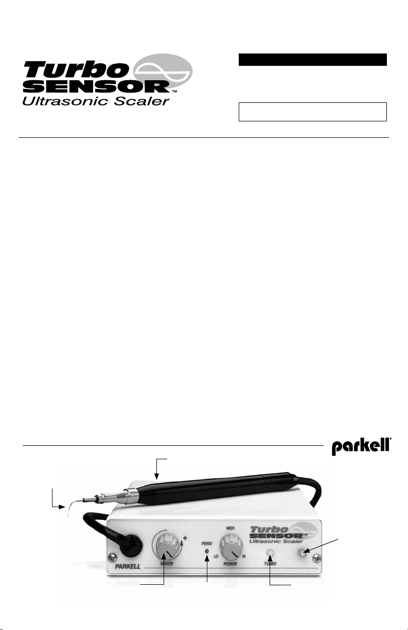
25KHZ O R 30KHZ INSERTS:
Device automatic ally switches
operating frequency to match
(insert not included).
WATER CONTROL
KNOB
AUTOCLAVA BLE REM OVABLE
HANDPIECE SHEATH.
“PERIO” LIGHT:
Indicates low-power range where
large changes in knob produce
subtle changes in tip amplitude.
“ON” INDICATOR:
Light s only when
footswitch is
depressed.
“TURBO” LIGHT:
Indicates the device is operating
in high- power “Turbo” mode
(footswitch fully depressed).

• This equipment produces electromagnetic
energy and may cause interference with other
nearby electronic devices. Should this occur,
changing the position or location of the
device may be necessary.
CLINICAL PRECAUTIONS
• Protect patient’s eyes, lips, cheek, tongue or
other vulnerable soft tissues when using this
device.
• Protect the patient’s clothing from water
damage when using this device.
• Clinicians should wear eye protection and
facemask when using this device.
• Water ow through tip during use must be
sufcient to cool handpiece and insert.
• Keep the long axis of the insert tip parallel to
the long axis of the tooth to wipe deposits
from the tooth.
• Do not gouge the tooth with the point of the
tip.
INDIVIDUALIZATION OF TREATMENT
If patient or operator is pregnant, or has any
medical condition which might be affected by
this device during treatment, consult a
physician prior to use.
CONFORMANCE TO STANDARDS
The Parkell TurboSENSOR is TUV listed and
conforms to IEC 60601-1, 60601-1-2 and CAN/
CSA C22.2 No. 601.1. Parkell’s quality system
is certied to ISO 9001/ISO13485. The device
is CE marked and is certied to European
Medical Device Directive (93/42/EEC).
The symbol
on the scaler indicates the
Protective Earth connection.
The symbol or is intended to alert the
user to the presence of important operating
and maintenance (servicing) instructions in the
literature accompanying the scaler
SPECIFICATIONS
• Power: 120VAC 50/60 Hz (D560 -110),
230VAC 50/60 Hz (D560 -230),
100VAC 50/60 Hz, 120VA (D560-100)
• Operating Temperature:
Between 50°F and 100°F (10°C - 38°C)
• Weight: 35 oz.
1
• Size: 1
⁄2” H x 5 1⁄2” W x 7” D
• Handpiece Operating Frequency:
25 KHz or 30 KHz
• Protection Against Electric Shock:
Class 1, Type B applied part
• Protection Against Ingress of Liquids:
Foot Switch & Scaler: IPX1 (drip proof);
Power Supply: IPX0 (Ordinary)
• Mode of Operation of Equipment:
Intermittent – 10 minutes on, 5 minutes off
• Operating Conditions:
15-30°C, 10-80% RH (non-condensing)
• Transport and Storage Conditions:
10-40°C, 10-80% RH (non-condensing)
WHAT’S INCLUDED:
• (1) Magnetostrictive Scaler Control Unit with
attached handpiece, foot controller and water
line (with male quick-connect coupler);
(120VAC=Stock No. D560 -110 /
230VAC=Stock No. D560-230 /
100VAC=Stock No. D560-100)
• (2) Autoclavable sheaths (one attached to
handpiece) (Stock No. D576)
• (2) Inline water lters (one attached to water
line)
• (1) Transformer with cable
• (1) Operator’s Manual / Instructions for Use
INSERTS
Magnetostrictive Inserts for the TurboSENSOR
scaler are available separately, and are not
included with the basic scaler unit. The unit is
designed to work with Parkell inserts. For
information about usage with non-Parkell
inserts, please see our warranty policy. The
scaler automatically adjusts the operating
frequency to match that of the insert in the
handpiece without operator intervention. Brand
new inserts may t very tightly in the handpiece
initially, and may be inserted and removed
more easily by using a slight t wisting motion,
and by lubricating the insert “O” ring with water.
Old, worn or blunt inser ts will perform poorly,
generate excess heat, and should be replaced
when necessary.
INSTALLING YOUR SCALER
Locate the device where the control panel will
be easy to reach during scaling procedures,
and where the water lter at the rear of the unit
may be periodically changed without dif culty.
The scaler requires access to a grounded
electrical outlet and a source of drinking-quality
water. The device and its separate transformer
generate a minimal amount of heat. Avoid
covering them, to allow normal cooling.
WATER CONNECTION
Before plugging in the device, connect the
scaler’s water line to a drinking- quality water
supply (15-35 psi optimal), free of sediment. An
external, ofce-wide water lter is
recommended to minimize frequent changes of
the device’s in-line water lter. The male
quick-connect that comes on the end of the
water hose is the standard tting presently used
in the dental industry. If you are replacing a
scaler that uses an Adec-type or other type of
connection, remove the old tting from the unit
hose and attach it to the
new water line. Check
for leaks at all hose and
lter connections before
use, and tighten if
necessary.
CONTRO LLING TH E WATER FLOW
Observing the arrow printed on the control
panel, turn the water control counter-clockwise
to increase the ow, or clockwise to decrease
water ow. If water does not ow through the
insert when the foot pedal is depressed, the
water passage in the scaling inser t may be
clogged.
ELECTRICAL CONNECTION
The scaler must only be powered via the
Transformer Assembly that is supplied with the
device by Parkell.
1. Plug the round transformer power cord
connector into the back of the scaler, with the
arrow on the plug on top.
2. Plug the transformer into a grounded
electrical outlet. Stepping on the pedal will
activate the scaler.
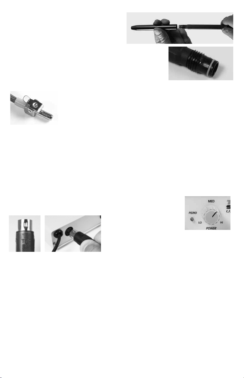
USE OF AUTOCLAVABLE S HEATHS
AND ULTRASONIC INSERTS
1. The TurboSENSOR handpiece is provided
with the autoclavable handpiece sheath
attached. Prior to use, the sheath should be
sterilized. To remove it, hold the handpiece at
the base with one hand and turn the sheath
counter-clockwise with the other, taking care
not to twist the hose. The sheath will unscrew
and slip off.
2. To replace
the sheath,
gently thread
it onto the
handpiece
clockwise,
until there is no gap between the two. Take
care not to damage or dislodge the O -ring.
Do not overtighten.
TURNI NG ON THE SCALER AND
CONTROLLING THE POWER OUTPUT
The unit does not have a traditional on/off
switch. The foot pedal turns the unit on when
depressed, and off when released. The pedal
should be placed where it will not
accidentally be pressed when the device is
not in use.
The TurboSENSOR gives you two ways to
adjust the scaling power, by using the Power
Control Knob for normal operation, or by
depressing the Foot Pedal to enter the “Turbo
Mo de”.
Use the Power Control
Knob to set the initial
scaling power for the
procedure at hand.
Turn the knob in a
clockwise direction to
increase the power, or counterclockwise to
decrease the power.
• Usually, the Power Control Knob is set at the
“Medium” setting to start. When the foot pedal
is slightly depressed to the rst position, the
insert will begin vibrating at Medium power.
• If the Power Control Knob is set for the “Perio”
setting, the “Perio” light will illuminate, and the
tip will vibrate at a much a lower power than a
traditional scaler when the foot pedal is
depressed. This permits very subtle
adjustments in tip power, meaning that
relatively large movements of the knob within
the Perio mode of operation will produce small
increases in power. This allows more
comfortable debridement for sensitive
patients.
• When the “Perio” light is not illuminated, tip
amplitude reacts more dramatically to knob
adjustment for high power calculus removal.
 Loading...