

PARK AUDIO df1404 mkII, DF1408 MkII, DF, DF2804 MkII Owner's Manual

FOUR-CHANNEL
DF - series
PROFESSIONAL POWER AMPLIFIER
DF1404
MkII
OWNER'S MANUAL

ACCESSORIES:
1. Power cord
2. Owner’s Manual
3. Warranty

GENERAL
The DF1404 MkII professional digital four-channel amplifier is designed for high
fidelity amplification of sound signals within a professional sound reproduction system.
The amplifier can be operated in a four-channel mode, three-channel mode (one pair of
channels bridged) or two-channel mode (both pairs of channels bridged).
To ensure the most advantageous and faultless operation of the amplifier, please,
read this Manual before use.
UNPACKING
The manufacturer’s quality control system provides for careful examination of each
product before it leaves the factory to ensure its flawless appearance. After unpacking,
please, check the unit for any physical damage. In case of damage, please, contact your
local dealer. Keep the shipping carton and all packing material as you may need them for
re-shipment of the unit.
AVIS
RISQUE DE CHOC ELECTRIQUE
NE PAS OUVRIR
CAUTION! The amplifier runs on 230V AC voltage. Removing the cover will expose you
to a potentially dangerous voltage! Do not use the unit if the electrical power cord is frayed
or broken.
Power is supplied from 230 V AC single-phase grounded 50/60 Hz source!
CAUTION! The amplifier can yield dangerous output voltage! Do not touch the non-
insulated cable parts connected to the unit in operation!
CAUTION! The high sound pressure level of speaker systems generated by high output
power delivered by the amplifier may be hazardous to your hearing. Please, take adequate
safety precautions.
WARNING! The amplifier yields high output power. The manufacturer shall not be held
responsible for any damage to the speakers caused by excessive power from the unit.
WARNING SIGNS:
Important information! Intended to warn the user about any important
applicable information contained in this Owner’s Manual.
Hazardous voltage inside! Intended to warn the user about electric shock
hazard due to high voltage inside the product.
2

DESIGN FEATURES
Physical Design
The amplifier is enclosed in a metal (steel) case of 88 mm (2U) height. The amplifier
is designed to be standard rack-mounted (RACK 19"). Physically, the amplifier
consists of:
• power supply unit;
• four digital amplifying units installed on a common heat sink;
• input unit;
• indication and input level control unit.
Power Supply Unit
All four channel of the amplifier share the same pulse power supply unit.
Cooling System
The amplifier features a forced cooling system which is common for all four
channels. The amplifier and the power supply unit are cooled with a single fan blowing
backwards. The cooling system provides for a double-step intensity-cooling rate switching.
At a normal temperature, the fan runs at a low speed, thus generating the least noise
possible. When the amplifier is set to deliver a high output power or when the ambient
temperature is higher than normal, the cooling system may switch the fan to the other
(higher) cooling rate.
Output Stage
The output stage of this digital power amplifier is designed according to Class D
technology to deliver high efficiency and least heat. The high switching rate ensures the
high sound quality comparable with the best analogue amplifiers.
Balanced Inputs
The use of balanced inputs provides for an essential reduction of the environmentinduced hum and noise interference with long input connecting cables.
Line Outputs(only for standart input modules or input modules with a sensitivity
The amplifier line outputs are parallel to the inputs (each along the respective
channel) and provide for parallel connection of several amplifiers with standard signal
cables using XLR connectors.
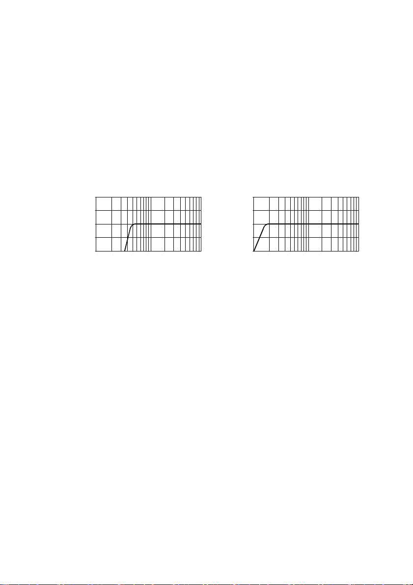
Input Filter
To improve the performance of loudspeakers, the amplifier incorporates a switchselectable high-pass 4-th order filter with 24dB per octave slope rate. This is the filter
recommended by all major loudspeakers manufacturers. This filter cuts off any signals
below 45 Hz, which generally cannot be reproduced by most of the professional
loudspeakers.
The filter significantly reduces the travel of the LF loudspeaker cone below the
loudspeaker frequency cut-off point (which is especially good for bass reflex loudspeakers)
3
thus making it possible to increase the power applied to the LF speaker without any danger
10 dB
-10dB
10 dB
of its overheating. The power of the amplifier is not wasted for cone flapping and allows
the loudspeaker to achieve higher sound pressure.
When it is necessary to achieve a linear frequency response to drive full-range
loudspeakers generally used in studios or in cinema theatres, the input filter can be
disabled (bypassed for each channel individually) with the slide switches located on the
amplifier rear panel.
Below see the enabled and disabled filter low frequency response diagrams.
Low Frequency Response for Enabled and Disabled Input Filter
5dB
0dB
-5 dB
-10dB
20Hz 50Hz 100Hz
«ON (45Hz )»
200Hz 900Hz
5dB
0d B
-5 dB
20Hz 50Hz 100Hz
«OFF»
200Hz 900Hz
Built-in Two-Way Crossover
This feature is to save your money and effort when driving two-way loudspeakers.
The bandwidth (high, low, full range signal) is selected individually for each channel with
a slide switch. The crossover frequency point is factory preset (generally to 150 Hz).
However, it can be changed by replacing the crossover PCB. If you need to change the
setting, please, consult our local dealer or the manufacturer’s support service by e-mail:
support@parkaudio2.com
Input Level Attenuators
These allow setting the amplifier to the required sensitivity (each channel individually)
which is very helpful when several amplifiers are used to drive different types of
loudspeakers or are used within multi-speaker sound reinforcement systems. The
attenuators are located on the front panel.
Optoelectronic Clip-Limiter
The clip-limiter is to reduce the input signal level as soon as any emergency or
overload occurs to prevent any sound distortion.
Removable Power Cord
This feature is provided for convenience of transportation and rack mounting.
4

FUNCTIONAL FEATURES
Overload and Short-Circuit Protection
Individual per each channel. This protective system becomes active in case of shortcircuited output or overload caused by reduced load impedance. It disables the output
signal of the respective channel for 0.5 second and then the amplifier gradually resumes
its delivery.
DC Output Protection
The amplifier’s schematics precludes transit of any clicks or noise during the poweron/off transition process. The power source unit is responsible for preventing any DC
damage to loudspeakers. In the event of output DC voltage or any powerful LF fluctuations,
the power source unit goes off and all indicators, including the POWER LED, go off too.
The amplifier can be restarted in 2 or 3 minutes by de-energizing and re-energizing
the amplifier with the POWER switch. If the DC is an occasional problem (which is
unlikely) the amplifier goes on and resumes its normal functioning. If, otherwise, the DC
output problem persists through the fault of the amplifier, then upon switching, the amplifier
goes on, the POWER amplifier goes on but in a short while the DC output protection
system disables the power supply source.
High Frequency Protection
Should any powerful high frequency fluctuations occur on the output either as a result
of poor contact in the input cable connectors, or being transmitted to the amplifier’s input
by any other device (such as a crossover or mixing console), the protection system
activates the built-in optoelectronic Clip-limiter to reduce the input signal level. Thus the
protection system effectively prevents any damage to tweeters as might be caused by
non-musical signals of powerful high frequency spectrum.
Thermal Protection
The continuous-operation-support protection system is common for four channels.
When the heat sink becomes heated over 50°С, the fan goes into its maximum speed
mode (normally, the fan runs at its minimum at a low speed). If the temperature of the heat
sink rises further to 65°С, the next stage of the thermal protection system goes active. It
is a built-in Clip limiter which reduces the input signal level (for all channels at a time)
without distorting the amplified signal. In this case the thermal protection LED becomes
slightly lit (dim). The higher the temperature, the lower signal level, the brighter is the LED.
Such an algorithm ensures faultless and continuous functioning of the amplifier even in
case of overheating.
The amplifier may stop functioning only in case of the fan breakdown or blocked air
flow. In this case upon reaching 85°С, the independent protection system disables the
respective channel of the amplifier. The CLIP LED goes on and the SIGNAL LED of the
affected channel goes off. The amplifier resumes its operation in the reverse order.
5

As soon as the amplifier cools down, the affected channels gradually regain their
amplification level up to the set value.
Soft Signal Start
During the power-on process, this feature ensures smooth gain from zero to the
maximum level to provide for a smooth rise of the sound level emitted from the
loudspeakers.
6
 Loading...