

Page 1

T6T VHF 100 W Transmitter
User Documentation
Page 2

Page ii T6T VHF 100 W Transmitter
Handbook Title: T6T VHF 100 W Transmitter User Documentation
Handbook Part Number: 31-3T6T100V
Handbook Version: 2.0
Date of Issue: February 2005
Equipment Modification Level 7
Published By: Park Air Systems
Northfields
Market Deeping
Peterborough PE6 8UE
England
Telephone: From UK, 01778 345434
From outside UK, 44 1778 345434
Fax: From UK, 01778 342877
From outside UK, 44 1778 342877
www.parkairsystems.com
Errata
Any errors found in this handbook are promulgated through the Park Air FTP network. Any
user can access this information by logging on to:
ftp.parkairsystems.com
When logged on, select the public (Pub) folder, then the Handbook Errata Sheets folder,
and then select the required equipment model.
[Adobe Acrobat™ must be loaded on your PC to use this facility]
Page 3

T6T VHF 100 W Transmitter Page iii
Health and Safety
Warnings
A warning is used to indic ate possibl e danger to per sonnel. Th roughout Par k Air hand books, warni ngs
are indicated by the following symbols:
Cautions
A caution is used to indicate possible danger to the equipment.
Trademarks
The following tradenames are used in this handbook.
IBM This is a registered trademark of International Business Machines.
Microsoft This is a registered trademark of Microsoft Corporation in the USA and other
countries.
Windows This is a registered trademark of Microsoft Corporation in the USA and other
countries.
Indicates electrical danger to personnel.WARNING
Indicates a hazardous material.
WARNING
Indicates a non-ionizing radiation hazard.
WARNING
Indicates a specified danger to personnel.
WARNING
Indicates the presence of electrostatic sensitive devices (ESSD). Caution
Indicates a specified danger to the equipment. Caution
Page 4

Page iv T6T VHF 100 W Transmitter
List of Abbreviations
ac alternating current
AGC automatic gain control
AM amplitude modulation
ATC air traffic control
BER bit error rate
BIT built-in test
C celsius
CD compact disk
dB decibel
dc direct current
DSB double sideband
E-BIT external bit signal
ESSD electrostatic sens iti ve devi ces
Fig figure
FM frequency modulation
Hz hertz
IF intermediate frequency
kg kilogramme
kHz kilohertz
LCD liquid crystal display
mmetre
mA milliamp
MARC multi-access remote control
mm millimetre
mW milliwatt
MHz megahertz
MSK minimum shift keying
PA power amplifier
PC personal computer
PCB printed circuit board
pk-pk peak-to-peak
ppm parts per million
PSU power supply unit
PTT press to transmit
RF radio frequency
ROM read-only memory
RSE2 remote site equipment
RSSI receiver signal strength indication
Vvolt
VFP virtual front panel
VHF very high frequency
VOGAD voice-operated gain adjusting device
VSWR voltage standing wave ratio
Wwatt
Page 5

Approvals and Standards T6T VHF 100 Watt Transmitters
Approvals:
The equipment is designed to meet the essential requirements of Directives
1999/5/EC, 89/336EEC as amended by Directive 93/68/EEC, and 72/23/EEC.
Standards:
The following standards are applied:
EMC EN 301 489-1; EN 301 489-22.
Health & Safety, EN 60950, CAN/CSA-C22.2 No. 60950, UL 60950.
Radio EN 300 676, IC RSS141, FCC part 15 and 87.
Telecom CS-03.
FCC Statement:
This device has been tested and found to comply with the limits for a Class B digital
device, pursuant to part 15 of the FCC Rules. These limits are designed to provide
reasonable protection against harmful interference in a residential installation.
This equipment generates, uses and can radiate radio frequency energy and, if not
installed and used in accordance with the instructions, may cause harmful
interference to radio communications. However, there is no guarantee that
interference will not occur in a particular installation.
If this equipment does cause harmful interference to radio or television reception,
which can be determined by turning the equipment off and on, the user is
encouraged to try to correct the interference by one or more of the following
measures:
-Reorient or relocate the receiving antenna.
-Increase the separation between the equipment and the receiver.
-Connect the equipment into an outlet on a circuit different from that to which the
receiver is connected.
-Consult the supplier or an experienced radio/TV technician for help.
Operation on 8.33 kHz channel spacing is restricted to European customers.
Page 6

Page vi T6T VHF 100 W Transmitter
About This Hard Copy
This document, apart from th e preface, is a hard copy of the files contained on the CD and co mprises
the following parts:
Preface (not on CD)
Introduction
Specification
Operation
Installation
Maintenance.
Page 7

Back to Transmitter
Main Page
Introduction
This topic gives a brief introduction to the T6T VHF 100 W Multimode Transmitter.
Page 8
T6T VHF 100 W Transmitter Page 2 Introduction
Back to Transmitter
Main Page
Purpose
The T6T VHF multimode 100 W transmitter i s intended for use in fix ed ground environm ents such as
airports and en-route centres. The transmitter operates in voice and ICAO defined data modes at
frequencies between 118 and 136.975 MHz.
Dependent on the software loaded into the radio, the following operating modes can be selected:
❑ AM-Voice. All transmitters have this mode
❑ AM-MSK (optional)
❑ Mode 2 (optional)
❑ Mode 3 (optional).
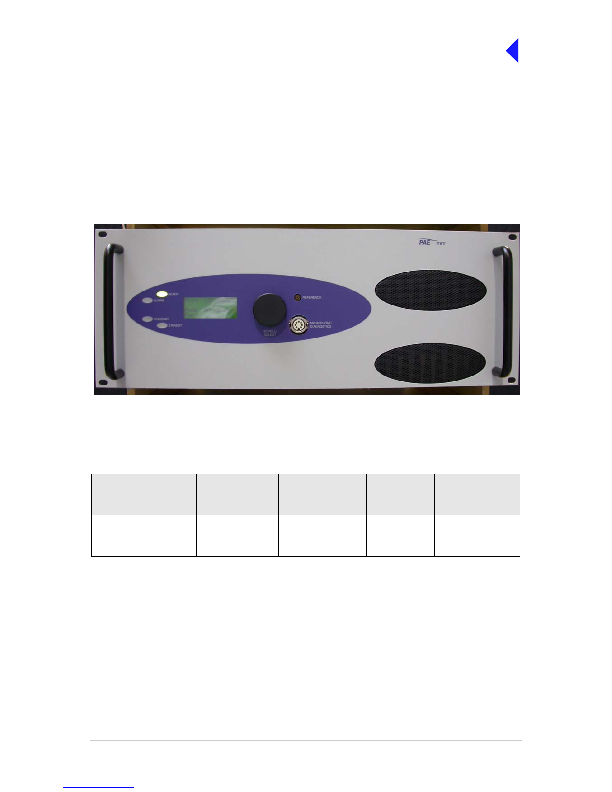
Fig 1 T6T VHF 100 W Transmitter
Models and Part Numbers
The following table identifies the T6T VHF 100 W transmitters:
Mechanical Installation
The transmitter fits i nto a n i ndu st rial st andard 19 inch (483 mm) e qui pme nt c ab inet and occupies 4U of
space.
Description Part Number Frequency Range Channel
Spacing
(AM-Voice)
Special
Applications
T6T 100 W standard
frequency coverage high
stability transmitter
B63100HS/NB 118 to 136.975MHz 25 kHz or
8.33 kHz
Supports 5-offset
carrier operation
Page 9
T6T VHF 100 W Transmitter Page 3 Introduction
Back to Transmitter
Main Page
Frequency Selection
T6 radios operate with 8.33 kHz and 25 kHz channel spacing. The radios recognize frequencies entered
in ICAO format and automatic ally ad just to t he correc t channe l spacing. For m ultichan nel operati on up
to 100 preset frequency cha nnels can be stored in the radio for immediate recall; any combina tion of
8.33 kHz and 25 kHz channel spacing can be stored. Any valid operating frequency can be selected from
the radio’s front panel or a compatible remote control equipment.
Operating Parameters
The transmitter’s o perat ing parameters are set usi ng th e fr on t pa nel mu lti -pur po se Sc r oll/S ele ct switch,
or by using the Park Air Virtual Front Panel (VFP) software in conjunction with a Personal Computer (PC).
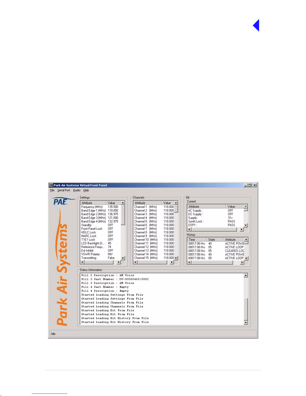
Virtual Front Panel
The Virtual Front Panel (VFP) software supplied on CD with the radio is compatible with any PC or laptop
running Windows 2000™ or Windo ws XP ™. T he VFP allo ws ch ang es to a rad io’s setti ngs and cha nnel
information, it dis plays the current B IT state, display s BIT history, allo ws security lo cks to be set, and
provides maintenance facilities. A typical VFP presentation is shown in Fig 2. Usi ng th e VFP has s ever al
advantages over setting a radio from the front panel; these are:
❑ A profile of the operationa l setti ngs an d chann el inform ation c an be crea ted, sto red on di sk, and
then recalled to download into other radios.
❑ A print out of the radio’s profile can be made from the VFP.
❑ The front panel controls can be locked. Front Panel Lock is available only when using the VFP.
Fig 2 Typical VFP Presentation
Page 10

Back to Transmitter
Main Page
Intentionally Blank
Page 11

Back to Transmitter
Main Page
Specification
This section gives the specification applicable to the T6T VHF 100 W Multimode Transmitter
operating in AM modes, Mode 2 and Mode 3.
All radios operate in AM-Voice mode. Additional software must be loaded to allow AM-MSK,
Mode 2 and Mode 3 operation.
Page 12
T6T VHF 100 W Transmitter Page 2 Specification
Back to Transmitter
Main Page
General Specification
The general specific ation app lies to the T6T 100 watt transm itter irre spective of the sele cted oper ating
mode. Separate listings are given for AM modes, Mode 2 and Mode 3. One model of the T6T VHF 100 W
Multimode Transmitter is available as detailed in Table 1.
Frequency accuracy
The frequency accuracy is better than 0.3 ppm.
Number of Channels
The transmitter has a multichannel capability. 100 channels can be stored and recalled.
Power Requirements
The transmitter operates from an ac mains supply, or a dc input supply. When both supplies are
connected, the dc input acts as an automatic backup for the ac mains.
ac input supply The transmitter opera tes from a 48 to 62 Hz single-phase ac supply
and automatically adjusts to operate from any supply voltage ranging
from 110 Vac to 230 Vac ±10%. The power consumption figures are
given in Table 2.
dc input supply The transmitter operates from a dc input supply between 21.6 and
32 V (measured at the radio’s input). Current loading is given in
Table 2.
Table 1 100 Watt T6 Transmitter
Description Part Number Frequency Range Special Applications
100 watt, high stability, standard
frequency coverage transmitter
B63100HS/NB 118 to 136.975MHz Supports 5-offset carrier
operation
Table 2 Power Consumption
Requirement 100 Watt Trans mitte r Normal Operation
ac dc
Maximum 1000 VA 24 A
Typical 600 VA 17 A
Not Transmitting 90 VA 1.5 A
Page 13

T6T VHF 100 W Transmitter Page 3 Specification
Back to Transmitter
Main Page
Dimensions and Weight
The dimensions and weight of the 100 watt transmitter are:
Width 483 mm (19 inches).
Height 177.8 mm (7 inches). The height occupies 4U of equipment cabinet
space.
Depth 430 mm (16.9 inches) measured from front panel to rear panel.
465 mm (18.3 inches) measured from front panel to rear RF
connectors.
Weight 25 kg (55 pounds).
Environmental
Temperature range The transmitter operates to specification across the temperature
range of -20°C to +55°C.
The transmitter can be stored at temperatures ranging from
-30°C to +70°C without causing any damage.
Humidity The transmitter operates to specification at a relative humidity
between 5% and 90% non-condensing.
Altitude The transmitter operates to specification up to 15,000 feet.
Additionally it is capable of storage at altitudes up to 50,000 feet
without damage.
Shock and vibration The transmitter complies with shock and vibration protection
MIL-STD-810E, method 516.4, procedure VI - Bench Handling.
Ventilation The transmitter is cooled by integral fans, which normally runs at half
speed. At an RF PA temperature of 45°C this is increased to full speed
and at 40°C it reduces to half speed again.
The transmitter power supply units also use internal fans.
Warm up time The transmitter is fully operational within 20 seconds but can take up
to 10 minutes to achieve frequency accuracy for offset carrier.
Page 14

T6T VHF 100 W Transmitter Page 4 Specification
Back to Transmitter
Main Page
AM Modes
The transmitter can operat e in A M- Vo ice mo de ( st anda rd) and A M-MS K mo de ( opti on al). T he fo ll owing
specifications apply to both modes unless stated otherwise.
Transmitter RF Characteristics
RF Power Output
The RF car rie r ou t p ut po we r i s ad j us t ab le in 2 W steps from 10 W t o 1 0 0 W.As an option, the ma ximu m
selectable power can be limited. Output power is automatically controlled under the following conditions:
Frequency range Variations in power remain within 0 to +1 dB over the operational
frequency range.
Low supply voltage Variations in power remain within ±1 dB for supply voltages between
24 Vdc and 32 Vdc.
High VSWR Loop error can reduce power progressively by up to 3 dB. Variations
in power remain within ±1 dB into a VSWR of up to 2.5:1. At a VSWR
greater than this the output power may be reduced by 10 dB ±1 dB.
High RF PA temperature If the RF PA temperature sensor exceeds 80°C the output power is
reduced by 3 dB ±1 dB. If the RF PA temperature sensor exceeds
90°C the transmitter is de-keyed and automatically re-keyed at 70°C.
PA Module Failure If one of the two PA modules fails, the transmitter will continue to
operate at half power, 50 watts.
Duty Cycle
Both modes 100% continuous operation.
Channel Spacing
AM-Voice mode The transmitter is capable of both 25 kHz channel spacing and
8.33 kHz channel spacing.
AM-MSK mode 25 kHz.
Offset Carrier
AM-Voice mode The transmitter is capable of offsetting the carrier frequency to provide
2, 3, 4 and 5-carrier offset.
AM-MSK mode Offset carrier is not available.
Harmonic Outputs
Both modes Second harmonic outputs are less than -36 dBm, third harmonic
outputs are less than -46 dBm and fourth harmonic outputs and above
up to 4 GHz, are less than -56 dBm.
Page 15

T6T VHF 100 W Transmitter Page 5 Specification
Back to Transmitter
Main Page
Spurious Outputs
Both modes The spurious outputs are less than -46 dBm for modulation depths up
to 90%, measured at greater than 500 kHz from carrier in the
frequency range 9 kHz to 4 GHz. There are no coherent spurious
outputs above the spectral mask at less than 500 kHz.
Intermodulation
Both modes Intermodulation products, caused by an interfering signal with the
same power as the transmitter isolated by 30 dB, are at least -40 dBc
at ≥±150 kHz and -50 dBc at ≥±500 kHz.
Transmitter Modulation Characteristics
The transmitter modulation characteristics are as follows:
Mode
AM-Voice AM-Voice mode uses Double Sideband (DSB) Amplitude Modulation
(AM) full carrier; emission designator 6K80A3EJN for 25 kHz
channels and 5K00A3EJN for 8.33 kHz channels.
AM-MSK AM-MSK mode uses Double Sideband (DSB) Amplitude Modulation
(AM) full carrier; emission designator 13K0A2DJN.
Modulation Depth
Both modes The transmitter is capable of modulation depths up to 95%.
Hum and Noise
Both modes The hum and noise is more than 45 dB below the signal level for line
input levels <-13 dBm, and more than 50 dB below the signal level for
line input levels ≥-13 dBm, for a carrier modulated by a 1 kHz signal
with a modulation depth of 90%.
Frequency Response
25 kHz channel spacing AM-Voice and AM-MSK: The variation in frequency response with
reference to a 1 kHz signal is within +0.5 dB and -1.5 dB across the
frequency range 300 to 3400 Hz. The response is also less than
-20 dB at 100 Hz and below, and less than -30 dB at 4 kHz and above.
8.33 kHz channel spacing AM-Voice only: The variation in frequency response with reference to
a 1 kHz signal is within +0.5 dB and -1.5 dB across the frequency
range 350 Hz to 2500 Hz. The response is also less than -10 dB at
100 Hz and below, and less than -30 dB at 3200 Hz and above.
Distortion
25 kHz channel spacing The total harmonic distortion is less than 5% due to signals with a
modulation depth of 90%, within the frequency range 300 Hz to
3400 Hz.
8.33 kHz channel spacing AM-Voice only: The total harmonic distortion is less than 5% due to
signals with a modulation depth of 90%, within the frequency range
350 Hz to 2500 Hz.
Page 16

T6T VHF 100 W Transmitter Page 6 Specification
Back to Transmitter
Main Page
Residual FM
Both modes For a test signal of 1 kHz set at 80% modulation depth applied to the
line input of the transmitter, the unwanted peak frequency modulation
does not exceed ±500 Hz.
VOGAD
AM-Voice The VOGAD has an operational range of 30 dB. The VOGAD can be
disabled.
AM-MSK The VOGAD is disabled.
Mute
AM-Voice The mute level is set at 15 dB below the average speech line level
setting. The mute can be disabled.
AM-MSK The mute is disabled.
Differential Group Delay
AM-MSK There is less than 60 µs differential group delay for signals in the
range 1200 to 2400 Hz.
Transmitter Control
Transmitter cont rol characteristics are as follows:
Audio Inputs
Voice can be connected to the tr ansmitter via the front pan el micr ophon e connec tor. Vo ice can als o be
connected via the line inputs. Line level setting from -30 to +10 dBm.
PTT Time Ou t
The time out period is adjustable from 2 to 510 seconds in 2 second steps or it can be disabled.
Page 17

T6T VHF 100 W Transmitter Page 7 Specification
Back to Transmitter
Main Page
Mode 2
This section gives the tran smitt er spe cificati on appl icable to Mo de 2 oper ation. Mo de 2 paramete rs are
identical to AM-Voice mode parameters with the following exceptions:
RF Power Rise Time
The transmitter pr oduces more than 90% of ful l power output within the first 2 symbols of th e power
stabilization segment, which is the first segment of the training sequence and consists of 4 symbols each
representing 000.
RF Power Decay Time
The output power decays by more than 20 dB within 2.5 symbols of the middle of the final symbol.
Channel Spacing
25 kHz channel spacing only.
Transmitter Modulation Characteristics
Mode 2 uses Carrier Sense Multiple Access (CSMA) differentially encoded 8-phase shift keying
(D8PSK), using a raised cosine filter with α=0.6 (nominal value), emission designator 14K0G1DE.
Information is differentially encoded with 3 bi ts p er symb ol transmitted as changes i n pha se ra ther th an
absolute phase. Th e data stream i s divided into g roups of 3 con secutive data bit s, least signi ficant bit
first. Zeros are padded to the end of transmissions if needed for the final channel symbol.
Modulation Rate
The symbol rate is 10,500 symbols/second (±0.005%), resulting in a nominal bit rate of 31,500 bits/s.
RMS Phase Error
The RMS phase error is less than 3°. The error vector magnitude is less than 6%.
Phase Acceleration
The total frequency change during the transmission of the unique word is less than 10 Hz. After this, the
phase acceleration is less than 500 Hz/s.
Page 18

T6T VHF 100 W Transmitter Page 8 Specification
Back to Transmitter
Main Page
Mode 3
This section gives the tran smitt er spe cificati on appl icable to Mo de 3 oper ation. Mo de 3 paramete rs are
identical to AM-Voice mode parameters with the following exceptions:
RF Power Rise Time
The transmitter pr oduces more than 90% of ful l power output within the first 2 symbols of th e power
stabilization segment, which is the first segment of the training sequence and consists of 4 symbols each
representing 000.
RF Power Decay Time
The output power decays by more than 20 dB within 2.5 symbols of the middle of the final symbol.
Channel Spacing
25 kHz channel spacing only.
Transmitter Modulation Characteristics
Mode 3 uses Time Division Multiple Access (TDMA) differentially encoded 8-phase shift keying (D8PSK),
using a raised cosine filter with α=0.6 (nominal value), emission designator 14K0G7WET. Information is
differentially encoded with 3 bits per symbol transmitted as changes in phase rather than absolute phase.
The data stream is div ided into groups of 3 consecutiv e data bits, least significant bi t first. Zeros are
padded to the end of transmissions if needed for the final channel symbol.
Modulation Rate
The symbol rate is 10,500 symbols/second (±0.005%), resulting in a nominal bit rate of 31,500 bits/s.
RMS Phase Error
The RMS phase error is less than 3°. The error vector magnitude is less than 6%.
Phase Acceleration
The total frequency change during the transmission of the unique word is less than 10 Hz. After this, the
phase acceleration is less than 500 Hz/s.
Page 19

Back to Transmitter
Main Page
Operation
This topic describes the transmitter’s operating controls and indicators.
It also details how to set up the transmitter’s operating parameters.
Page 20

T6T VHF 100 W Transmitter Page 2 Operation
Back to Transmitter
Main Page
Controls, Indicators and Front Panel Connectors
This section describes the transmitter’s controls, indicators and front panel connectors.
Front Panel
The transmitter’s front panel is illustrated below.
Scroll/Select Switch and LCD
The Scroll/Select switch is used in conjunction with the LCD to select most of the transmitter's operational
settings. During normal operation, the LCD sh ows the o perating fr equency, the channel number (if t he
channel store facili ty is used), the carrier offset (if us ed), and displays a graphical rep resentation of
instantaneous peak power.
The example LCD s creen above show s the transmitter o perating on 11 8.000 MHz; the fr equency has
been preset as channel 100 and offset at +7.3 kHz.
Ready Indicator
A green indicator that lights when the transmitter is ready for use and no BIT faults have been detected.
Transmit Indicator
An amber indicator that lights when the transmit circuit is keyed and producing output power.
Alarm Indicator
A red indicator that either flashes, or lights, when a BIT fault has be en detected. BIT indications are
classified as either Alarms or Alerts.
If an ‘alert’ conditi on is detected, the Alarm indi cator flashes, the Ready i ndicator remains lit, and t he
transmitter remains operational. A BIT ‘alert’ is indicated if:
❑ The transmitter RF output power has reduced from its setting by more than 1 dB but not more than
3 dB.
❑ The supply volts falls below a pre-defined level.
Any other BIT condit ion results in an al arm. When detected, the Alarm indicator l ights and the Ready
indicator becomes unlit; the transmitter cannot be used.
READY
ALARM
TRANSMIT
STANDBY
SCROLL/
SELECT
MICROPHONE/
DIAGNOSTICS
REFERENCE
F r e q 1 1 8 .0 0 0 M H z
C h 1 0 0 + 7 . 3 k H z
P w r
Scroll/Select SwitchLCD
M o d e A M V o i c e 1
Page 21

T6T VHF 100 W Transmitter Page 3 Operation
Back to Transmitter
Main Page
Standby Indicator
A red indicator that lights whe n the transm itter i s in standby mode. Whe n in stand by mode , most of the
radio's circuits are inactive, the front panel LCD is blanked, and the transmitter cannot be keyed.
Standby mode is selected and deselected using the front panel Scroll/Select switch and LCD, by initiating
an instruction thro ugh a MARC system, th rough a T6 control ler or thro ugh th e VFP. For d etails of front
panel selection and deselection see page 14.
Reference Connector
An SMB jack socke t that allows a freq uency counter to moni tor the transmitter 's reference frequency .
This connector is used onl y for maintenan ce purpos es. The instr uctions for ch ecking and adjusting the
reference frequency are given in the Maintenance section.
Microphone/Diagnostics Connector
A dual purpose conne ctor that a llows either a m icro phone, o r a PC, to be c onnec ted to the transmi tter.
The connector is a 7-pin self-locking DIN socket; the pin-out is shown in Table 1.
A microphone is fitted to this c onnec tor to enab le the tra nsmit ter to be ope rated in AM loca l mode. T he
connections are detailed in Table 1. A PC can also be connected to allow the VFP to be displayed. Using
the VFP is detailed in t he Maintenance section. The PC connections at the transmitter are shown in
Table 2 on the following page.
Table 1 Microphone/Diagnostics Connector - Audio Connections
Pin
Number
Signal
Input or
Output
Description
1 Microphone ground - 0 V.
3 Microphone PTT Input 0 V to PTT.
5 Sidetone Output 0 to 3 V pk-pk.
6 Microphone input Input 2 to 35 mV rms on Passive setting and 8 to 140 mV rms on
Active setting to remain in VOGAD range.
7Ground - 0V.
Table 2 Microphone/Diagnostics Connector - PC Connections
Pin
Number
Signal
Input or
Output
Description
2 Transmit data Output RS232, 115200 baud, 8 data bits, 1 stop bit, no parity, no
handshaking.
Viewed from front
Page 22
T6T VHF 100 W Transmitter Page 4 Operation
Back to Transmitter
Main Page
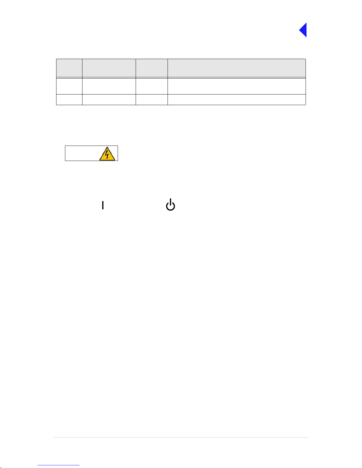
Rear Panel Power Switch
The rear panel power switch is a 2-way rocker switch used to select between power on, and standby.
When the Power switch is set to the Standby position, dangerous voltages are still present
in the transmitter's internal power supply circuitry. To ensure safe working, the transmitter
must be isolated from the ac and dc input supplies.
4 Receive data Input RS232, 115200 baud, 8 data bits, 1 stop bit, no parity, no
handshaking.
7 Ground - 0 V.
Table 2 Microphone/Diagnostics Connector - PC Connections
Pin
Number
Signal
Input or
Output
Description
WARNING
Dangerous Voltages
= Standby= On
Page 23

T6T VHF 100 W Transmitter Page 5 Operation
Back to Transmitter
Main Page
Setting Up and Operation
Introduction
Setting up the transmi tter involves using the front panel Sc roll/Select switch to specify the op erating
parameters.
Operating parameters can also be set using the Virtual Front Panel (VFP), through a Multi-Access
Remote Control (MARC) system , from an associat ed T6 controlle r. VFP operation is described on thi s
disk under Maintenance; MARC and T6 controller functionality is described in separate handbooks.
Table 9 on page 32 details the functions and parameters that can be set from all sources.
No attempt to set up the transmitter should be made until the installation procedures, given in the
Installation topic, are completed.
Normal Operation
During normal operation, the LCD displays the Main screen. This screen shows the operating frequency,
the channel number (if th e channel store facility is used), the car rier offset (if used), and displays a
graphical representation of output power when the transmitter is keyed. If the transmitter has been set to
Standby mode, which is shown by the front panel Standby indicator being lit, the LCD is blanked.
Using the Scroll/Select Switch
The Scroll/Select switch (refe rred to throughout this sect ion as the ‘Switch’) is used to leav e the Main
screen and display the Control screen (see page 8). Furth er use of t he Swit ch d ispla ys va rious s ele ction
menus and allows the r equired parameters to be set. The s witch has three actions: it can be tu rned
clockwise, anti-clockwise, or momentarily pushed in.
READY
ALARM
TRANSMIT
STANDBY
SCROLL/
SELECT
MICROPHONE/
DIAGNOSTICS
REFERENCE
F r e q 1 1 8 .0 0 0 M H z
C h 1 0 0 + 7 . 3 k H z
P w r
Scroll/Select SwitchLCD
M o d e A M V o i c e 1
Page 24

T6T VHF 100 W Transmitter Page 6 Operation
Back to Transmitter
Main Page
Screen Protocol
The following protocol is applicable to all screens described in this document.
Main Screen During normal operation, the Main screen (an example of which is shown below
whilst the transmitter is transmitting) is displayed.
Switch Refers to the front panel Scroll/Select switch. The switch is turned clockwise to scroll
through fields from left to right, and from top to bottom. The switch is turned
anti-clockwise to scroll through fields from right to left, and from bottom to top. The
switch is pressed to make a selection.
Time out If during any setting up procedure the Scroll/Select switch is not operated for
30 seconds, the display returns to the Main screen. If editing any parameter has not
been completed, the transmitter stays on the original setting.
>> Indicates more fields are available other than those currently displayed. To access
those fields, turn the switch clockwise through the last displayed field.
<< Indicates more fields are available other than those currently displayed. To access
those fields, turn the switch anti-clockwise through the first displayed field.
Back When Back is selected, you are returned to the previous menu.
Exit When Exit is selected, you are returned to the Main screen.
Menu System
The front panel control of the radio is implemented through a hierarchical menu system as shown on the
following page.
F r e q 1 1 8 . 0 0 0 M H z
C h 1 0 0 + 7 . 3 k H z
M o d e A M V o i c e
P w r I I I I I I I I I I
Page 25

T6T VHF 100 W Transmitter Page 7 Operation
Back to Transmitter
Main Page
Menu System
F r e q 1 1 8 . 0 0 0 M H z
C h 1 0 0
M o d e A M V o i c e
P w r I I I I I I I I I I
Settings
Set the
transmitter
operational
settings
BIT
Initiate a BIT
test and view
results
Standby
Enter or Exit
standby mode
Ref Freq
Adjust the
transmitter
reference
frequency
Band Edges
Set up the
transmitter
band edges
Polarities
Set the active
polarity for
certain hardwire
connections
Backlight
Adjust the
display’s
backlight
AM-Voice Mode
Settings
(see page 17)
AM-MSK Mode
Settings
(see page 19)
Digital Modes
(see page 20)
Mode and
Mode
Settings
Select Mode
Menu Lock Screen
Main Screen
(Example)
Displayed during normal
transmitter operation
Frequency
Set the
transmitter
operating
frequency
Channel
Set or recall up
to 100 preset
frequency
channels
Control Screen
Configure the transmitter
operating parameters, ac cess
the BIT facility or view the
software configuration
.
S/W Config
View the
transmitter
software
configuration
Page 26

T6T VHF 100 W Transmitter Page 8 Operation
Back to Transmitter
Main Page
Menu Lock Screen
A security facility available only from the VFP allows the transmitter front panel to be ‘locked’. When this
facility is active, no oper ational sett ings can be made fr om the front panel u ntil an ‘unlo ck’ command is
sent from the VFP.
The following screen is displayed when ‘lock’ is active, and the front panel switch is pressed.
To exit the system lock screen:
❑ Select OK, then press the switch. You are returned to the Main screen.
or,
❑ Wait for the 30 second time out to expire. You are returned to the Main screen.
Control Screen
The Control screen is ente red from the Main screen by pressin g the switch. The following screen is
displayed:
S E C U R I T Y M E S S A G E
F r o n t P a n e l
L o c k e d
O K
F r e q u e n c y
C h a n n e l
S e t t i n g s
E x i t > >
B I T
S / W C o n f i g
S t a n d b y
E x i t < <
Change the transmitter operating frequency.
Store or recall preset channel frequencies.
Select operating mode and mode se ttin gs .
Initiate a BIT test and view results.
View software configuration.
Enter or exit standby mode.
Page 27

T6T VHF 100 W Transmitter Page 9 Operation
Back to Transmitter
Main Page
Notes for Setting Up the Transmitter
The following notes should be read before setting up the transmitter. They advise on the special
frequency display when using 8.33 k Hz channel spacing, and give guidan ce on the optim um line leve l
settings. Note that for operation in the United States of America, this equipment is certified only for
operation using 25 kHz channel spacing.
Front Panel Display for 25 kHz and 8.33 kHz Channel Spacing
When setting the op erating fr equency of the trans mitter and 8.33 kHz channel s pacing is require d, the
displayed frequency differs from the actual channel frequency. Table 3 shows the pattern used for
25 kHz and 8.33 kHz spaced channel frequencies from 118.000 MHz to 118.141 MHz. The pattern is the
same for any frequency within the transmitter's frequency range. The display conforms to ICAO
convention for 8.33 kHz operation.
Table 3 25 kHz and 8.33 kHz Channel Spacing Displays
Actual Frequency
(to 4 decim al places)
Channel Spacing Displayed Frequency
at Transmitter's Front Panel
118.0000 MHz
118.0000 MHz
118.0083 MHz
118.0166 MHz
118.0250 MHz
118.0250 MHz
118.0333 MHz
118.0416 MHz
118.0500 MHz
118.0500 MHz
118.0583 MHz
118.0666 MHz
118.0750 MHz
118.0750 MHz
118.0833 MHz
118.0916 MHz
118.1000 MHz
118.1000 MHz
118.1083 MHz
118.1166 MH z
118.1250 MHz
118.1250 MHz
118.1333 MHz
118.1416 MHz
25 kHz
8.33 kHz
8.33 kHz
8.33 kHz
25 kHz
8.33 kHz
8.33 kHz
8.33 kHz
25 kHz
8.33 kHz
8.33 kHz
8.33 kHz
25 kHz
8.33 kHz
8.33 kHz
8.33 kHz
25 kHz
8.33 kHz
8.33 kHz
8.33 kHz
25 kHz
8.33 kHz
8.33 kHz
8.33 kHz
118.0 00 MHz
118.005 MHz
118.010 MHz
118.015 MHz
118.0 25 MHz
118.030 MHz
118.035 MHz
118.040 MHz
118.0 50 MHz
118.055 MHz
118.060 MHz
118.065 MHz
118.0 75 MHz
118.080 MHz
118.085 MHz
118.090 MHz
118.1 00 MHz
118.105 MHz
118.110 MHz
118.115 MHz
118.1 25 MHz
118.130 MHz
118.135 MHz
118.140 MHz
Page 28

T6T VHF 100 W Transmitter Page 10 Operation
Back to Transmitter
Main Page
Line Level Setting
The input line leve l s ett ing di spl ayed on the front panel is equ iv al ent to th e av erage speech level with a
peak-to-average ratio of 13 dB. This corresponds to the level specified for the lines.
When testing the transmitter using a sine wave, the line input level should be set to 10 dB above the line
level setting. The VOGAD and mute thresholds are preset at 10 dB and 15 dB respectively below the line
level setting.
Table 4 shows the relationship between the input line level, VOGAD threshold and mute threshold.
Table 4 Relationship Between Line Level, VOGAD Threshold and Mute Threshold
Line Level Setting
(dBm)
Average Speech
Level (dBm)
Sine Wave Level
(dBm)
VOGAD Threshold
(dBm)
Mute Threshold
(dBm)
+10 +10 +20 0 -5
+5 +5 +15 -5 -10
00+10-10-15
-5 -5 +5 -15 -20
-10 -10 0 -20 -25
-15 -15 -5 -25 -30
-20 -20 -10 -30 -35
-25 -25 -15 -35 -40
-30 -30 -20 -40 -45
Page 29

T6T VHF 100 W Transmitter Page 11 Operation
Back to Transmitter
Main Page
Changing the Transmitter Operating Frequency
The transmitter frequency can be changed in two ways: either from the frequency screen, or by recalling
a preset channel. This procedure details the use of the Frequency screen.
F r e q 1 1 8 . 0 0 0 M H z
C a n c e l O K
(1) From the Control screen, select
frequency to display the Frequency
screen.
(2) Turn the switch to hi ghlight the digit to
be changed, then press the switch.
(3) Turn the switch until the required digit
is shown, then press the switch.
(4) Repeat until the required frequenc y is
shown, then highlight OK and press the
switch.
(5) Only frequencies that fall betwee n the
band edge settings can be selected.
Page 30
T6T VHF 100 W Transmitter Page 12 Operation
Back to Transmitter
Main Page
To Store and Recall Frequency Channels
Up to 100 frequency channels can be stored in the transmitter.
C h 1 0 0
F r e q 1 2 1 . 5 0 0 M H z
R e c a l l
B a c k E x i t
C h 1 0 0
F r e q 1 1 8 . 0 0 0 M H z
S t o r e
B a c k E x i t
C h 1 0 0
F r e q 1 1 8 . 0 0 0 M H z
I n v a l i d f o r M o d e
B a c k E x i t
C h 1 0 0
F r e q 1 1 8 . 0 0 0 M H z
O u t s i d e B a n d E d g e
B a c k E x i t
To store a Channel Frequency:
(1) From the Control screen, select
Channel to display the Channel
screen. Highlight Channel, press the
switch and then turn it until the required
channel number is displayed; press the
switch.
(2) Highlight the MHz frequency value
(see Example 2) press the switch and
then turn it until the required MHz value
is shown. Press the switch.
(3) Highlight the kHz frequency value (see
Example 3), press the swi tch and the n
turn it until the required kHz value is
shown. Press the switch.
(4) Highlight Store and press the switch.
The new frequency is now stored in the
selected channel number.
To recall a Stored Frequency Channel:
(1) From the Control screen, select
Channel to display the Channel
screen.
(2) To make the transmitter operate on
any preset channel frequency,
highlight Channel and press the switch.
Turn the switch until the required
channel number/frequency is
displayed, then press the switch.
(3) Turn the switch to highlight Recall, then
press the switch . Exit the screen. Th e
transmitter now operates on the
recalled channel frequency.
Notes:
If a frequency outs ide the band edge limits is
entered, a message (see Channel Screen Example 3) is displayed.
If a frequency not valid for the mode of
operation is entered, a message (see Channel
Screen - Example 4) is displayed.
Channel Screen - Example 1
Channel Screen - Example 2
Channel Screen - Example 3
Channel Screen - Example 4
Page 31

T6T VHF 100 W Transmitter Page 13 Operation
Back to Transmitter
Main Page
To Initiate a BIT Test
Use the following procedure to initiate an interruptive BIT test from the transmitter front panel. A BIT test
cannot be initiated while the transmitter is keyed. After a BIT test has been run, the BIT screen is
displayed (see AM-Voice and AM-M SK BIT Screen on page 25). An interruptive BIT test cannot be
initiated in Mode 2 or Mode 3.
(1) From the Main screen , press t he sw itch to displ ay the C ontrol scree n. Turn t he sw itch until BIT
is highlighted. Press the switch.
(2) Ensure the BIT menu is displayed. Turn the switch until BIT Initiate is highlighted. Press the
switch.
(3) During the test, which takes approximately two seconds, the Testing screen is displayed.
B I T I n i t i a t e
E T I 0 0 0 0 0 : 0 0 h r s
A C S u p p l y O N
E x i t > >
T e s t i n g
P l e a s e W a i t
During an interruptive B IT test, t he tran smitt er radia tes modul ated c arrier wav es at the s et powe r.
Users should therefore obtain the necessary authority before initiating a test.
If the test is to be carried out with the antenna disconnected, ensure a load is fitted to the
transmitter's antenna connector.
In order to test the line input stages, an internally generated 1 kHz tone is injected into the line input
circuit. Any other audio present on the line input will cause the test to be inaccurate. Therefore the
transmitter must not be keyed during the test.
B I T
S / W C o n f i g
S t a n d b y
E x i t < <
Page 32

T6T VHF 100 W Transmitter Page 14 Operation
Back to Transmitter
Main Page
(4) On completion, and if the interruptive test was initiated from the front panel, one of the following
screens will be shown.
(5) Selecting OK takes the user back to the BIT screen.
(6) Selecting OK takes the user back to the BIT screen. The user can then scroll through the screen
to check out transmitter parameters for failure.
Standby Mode
Standby mode is a power saving feature that can be used for non-operational tr ansmitters. When in
standby mode, most of the transmitter's circuits are inactiv e, the LCD is blanked, and the transmi tter
cannot be keyed. To put the transmitter into standby mode, use the following procedure.
When the transmitter is in Standby mode, the red front panel Standby indicator is lit.
To Enter Standby Mode
To Exit Standby Mode
T e s t S t a t u s
P A S S
O K
T e s t S t a t u s
F A I L
O K
E n t e r S t a n d b y ?
Y e s N o
(1) From the Control screen select
Standby.
(2) At the Standby screen, select Yes.
(3) Check that the display blanks and
the front panel Standb y indicator is
lit.
E x i t S t a n d b y ?
Y e s N o
(1) Press the Switch.
(2) Select Yes.
(3) Check that the Main screen is
displayed and that the front panel
Standby indicator is unlit.
Page 33

T6T VHF 100 W Transmitter Page 15 Operation
Back to Transmitter
Main Page
Settings
Operational settings for the T6T 100 W VHF transmitter a re configured at the front panel, thr ough the
VFP, and through an associated MARC system (or compatible control system). Some settings can also
be made remotely via a T6 controller. The Settings screen is entered from the Control screen.
The settings that can be selected at the front panel Settings screen are:
❑ Mode - either AM-Voice, AM-MSK, Mode 2 or Mode 3
❑ Mode settings - allows the selected mode parameters to be set
❑ Polarities
❑ Band edges
❑ Backlight
❑ Reference frequency.
Note that the mode selec tion, refer ence frequen cy and ba cklight are s et from th is screen. W hen mode
settings, polarities and band edges are selected the user is taken to other screens.
General and mode sp ecifi c sett ings, s howin g defaul t valu es, are r efere nced in Table 5 on the following
page. Click on any required parameter by page number for further references.
M o d e A M V o i c e
M o d e S e t t i n g s
P o l a r i t i e s
E x i t > >
B a n d E d g e s
R e f F r e q 5 0 . 0 %
B a c k l i g h t 0 3 0 s
E x i t < < > >
B a c k
E x i t
Select between AM-Voice, AM-MSK, M ode 2 or Mode 3.
Select to take you to the mode specific Settings menu.
Select to take you to the Polarities menu.
Set the transmitter’s frequency band edges.
Align the transmitter’s reference frequency (Note 1).
Adjust the LCD’s backlight time out (Note 2).
Notes:
1. Setting the transmitter reference frequency is a maintenance operation. The current value
should not be reset unless the correct test equipment is connected. See the Maintenance
section.
2. The LCD bac kli ght ca n b e s et for pe rm ane ntl y on, off, or timed to stay on for a period between
15 and 120 seconds.
Page 34

T6T VHF 100 W Transmitter Page 16 Operation
Back to Transmitter
Main Page
Table 5 Operational Settings from the Front Panel
Parameter Mode Adjustment Range Factory Default Setting Further
Reference
Menu lock screen All Locked or unlocked Unlocked page 8
Enter standby
mode
All Yes or No - page 14
Exit standby mode All Yes or No - page 14
Set mode of
operation
All AM-Voice, AM-MSK, Mode
2 or Mode 3
AM-Voice page 15
Set polarities AM-Voice,
AM-MSK
STD or INV STD page 21
Band edges All 118.000 to 136.975 MHz 118.000 and 136.975 MHz page 29
LCD backlight All 15 to 120 s, On or Off 30 s page 15
RF power All 10 to 100 W 100 W page 17
Audio line in level AM-Voice,
AM-MSK
-30 to +10 dBm -13 dBm page 17 and
page 19
Inhibit AM-Voice,
AM-MSK
On or Off Off page 17 and
page 19
PTT (key) AM-Voice,
AM-MSK
On (key), Off (de-key) Off page 17 and
page 19
Tx time out AM-Voice,
AM-MSK
2 to 510 s or Off 180 s page 17 and
page 19
Modulation depth AM-Voic e,
AM-MSK
5 to 95% 85% page 17 and
page 19
Mute AM-Voice On or Off On page 17
VOGAD AM-Voice On or Off On page 17
Antenna C/O delay AM-Voice
AM-MSK
On or Off On
Off
page 17
page 19
Offset AM-Voice 0, ±2.5, ±4, ±5, ±7.3, ±7.5,
±8 kHz
0 (No offset) page 18
Step AM-Voice 8.33 kHz, 25 kHz or both 25 kHz page 18
Mic AM-Voice Active or Passive Passive page 18
Key priority AM-Voice,
AM-MSK
Local-Remote or
Remote-Local
Local-Remote page 18 and
page 19
Local PTT AM-Voice,
AM-MSK
Enabled or Disabled Enabled page 18 and
page 19
Remote PTT AM-Voice,
AM-MSK
Enabled or Disabled Enabled page 18 and
page 19
Remote phantom
PTT
AM-Voice,
AM-MSK
Enabled or Disabled Enabled page 18 and
page 19
Page 35

T6T VHF 100 W Transmitter Page 17 Operation
Back to Transmitter
Main Page
AM-Voice Settings Procedure
During this procedure, the following parameters, applicable to AM-Voice operation, can be set:
❑ RF power output
❑ Audio line input level
❑ Inhibit
❑ PTT on (key) or off (de-key)
❑ Transmitter time out
❑ Modulation depth
❑ Mute (on or off)
❑ VOGAD (on or off)
❑ Antenna c/o delay (on or off)
❑ Offset
❑ Step
❑ Mic
❑ Key priority (local or remote)
❑ Enable or disable local PTT
❑ Enable or disable remote PTT
❑ Enable or disable remote phantom PTT.
AM-Voice Mode Settings Screen
The AM-Voice mode setti ng screen is acc essed from the Settings screen. Use the Sc roll/Selec t switch
to select the parameter, then enter the required setting(s).
P o w e r 1 0 0 W
L i n e I n - 1 3 d B m
I n h i b i t O F F
E x i t > >
P T T O F F
T X T i m e o u t 1 8 0 s
M o d D e p t h 8 5 %
E x i t < < > >
M u t e O N
V O G A D O N
A n t C / O D e l O N
E x i t < < > >
Adjustments
RF power between 10 W to 100 W.
Audio line in level between -30 to +10 dBm.
On or Off.
On (key), Off (de-key).
2 to 510 s.
5 to 95%.
On or Off.
On or Off.
On or Off.
Page 36

T6T VHF 100 W Transmitter Page 18 Operation
Back to Transmitter
Main Page
O f f s e t 0 . 0 k H z
S t e p 2 5 k H z
M i c P A S S I V E
E x i t < < > >
K e y P r i o r i t y L - R
L o c a l P T T E N
R e m o t e P T T E N
E x i t < < > >
R e m P h a n P T T E N
B a c k
E x i t < <
Adjustments
0, ±2.5, ±4, ±5, ±7.3, ±7.5, ±8 kHz.
25 kHz, 8.33 kHz or both.
Active or Passive.
Local-remote or Remote-local.
Enabled or Disabled.
Enabled or Disabled.
Enabled or Disabled.
Return to Settings screen.
Page 37

T6T VHF 100 W Transmitter Page 19 Operation
Back to Transmitter
Main Page
AM-MSK Mode Settings Procedure
During this procedure, the following parameters, applicable to AM-MSK operation, can be set:
❑ RF power output
❑ Audio line input level
❑ Inhibit
❑ PTT on (key) or off (de-key)
❑ Transmitter time out
❑ Modulation depth
❑ Antenna c/o delay (on or off)
❑ Key priority (local or remote)
❑ Enable or disable local PTT
❑ Enable or disable remote PTT
❑ Enable or disable remote phantom PTT.
AM-MSK Mode Settings Screens
The AM-MSK mode setting screen is accessed from the Settings screen. Use the Scroll/Select switch to
select the parameter, then enter the required setting(s).
P o w e r 1 0 0 W
L i n e I n - 1 3 d B m
I n h i b i t O F F
E x i t > >
P T T O F F
T X T i m e o u t 1 8 0 s
M o d D e p t h 8 5 %
E x i t < < > >
A n t C / O D e l O N
K e y P r i o r i t y L - R
L o c a l P T T E N
E x i t < < > >
R e m o t e P T T E N
R e m P h a n P T T E N
B a c k
E x i t < <
Adjustments
RF power between 10 W to 100 W.
Audio line in level between -30 to +10 dBm.
On or Off.
On (key), Off (de-key).
2 to 510 s.
5 to 95%.
On or Off.
Local-remote or Remote -local.
Enabled or Disabled.
Enabled or Disabled.
Enabled or Disabled.
Page 38

T6T VHF 100 W Transmitter Page 20 Operation
Back to Transmitter
Main Page
Mode 2 Settings Screen
This is an advisory screen. Pressing OK returns the user to the Main screen.
Mode 3 Settings Screen
This is an advisory screen. Pressing OK returns the user to the Main screen.
M o d e 2 p a r a m e t e r s
a r e s e t v i a t h e
H L D C i n t e r f a c e
O K
M o d e 3 p a r a m e t e r s
a r e s e t v i a t h e
T 1 / E 1 i n t e r f a c e
O K
Page 39

T6T VHF 100 W Transmitter Page 21 Operation
Back to Transmitter
Main Page
Polarities Screens AM-Voice and AM-MSK
A number of remote in dic ation and control signals ca n be hardwire connected to the transmitter. These
signals include a transmitter ready indication, a PTT control signal, a phantom PTT control signal, a PTT
out indication, a tran smitter inhibit c ontrol signal, an E -BIT input, a BI T test initiation c ontrol signal, an
external VSWR fault indication and antenna C/O. The following paragraphs detail the signals applicable
to the operational mode of the transmitter.
The Polarities screen is accessed from the Settings screen.
AM-Voice and AM-MSK Polarity Settings
Each of ten polarity settings applicable to AM-Voice and AM-MSK can be set to the default STD
(standard) setting or INV (inverted).
The signal connections are shown in Table 6 along with the conditions when STD or INV is selected.
The settings for the PTT Reference voltage are also shown in Table 6.
R e a d y O u t S T D
E - B I T I n S T D
I n h i b i t I n S T D
E x i t > >
B I T S t a r t I n S T D
P T T R e f + 1 4 V
P T T I n S T D
E x i t > >
P h a n P T T I n S T D
P T T O u t S T D
F a s t P T T O u t S T D
E x i t < < > >
E x t V S W R I n S T D
A n t C / O O u t S T D
B a c k
E x i t < <
Page 40

T6T VHF 100 W Transmitter Page 22 Operation
Back to Transmitter
Main Page
Table 6 AM-Voice and AM-MSK Polarity Settings
Signal Connector Polarity set to STD Polarity set to INV
Ready Out Facilities, pin 13 An open collector grounded
output when the radio is ready
to transmit and no BIT faults
are detected.
An open collector high
impedance output when the
radio is ready to transmit and
no BIT faults are detected.
E-BIT In Facilities, pin 2 TTL input. 0 V indicates an
external fault.
TTL input. 5 V indicates an
external fault.
Inhibit In Facilities, pin 10 TTL input. 0 V inhibits
transmitter operation.
TTL input. 5 V inhibits
transmitter operation.
BIT Start In Facilities, pin 11 TTL input. 0 V initiates an
interruptive BIT test.
TTL input. 5 V initiates an
interruptive BIT test.
PTT In MARC, pin 4
MARC Audio, pin 6
Active when input differs from
reference by more than 10 V.
Inactive when input dif fers from
reference by less than 1 V.
Maximum input level ±60 V
with respect to reference. Input
will draw no more than 6 mA,
requires at least 1 mA to
operate.
Active when input differs from
reference by less than 1 V.
Inactive when input di ffers from
reference by more than 10 V.
Maximum input level ±60 V
with respect to reference. Input
will draw no more than 6 mA,
requires at least 1 mA to
operate.
Phantom PTT In
(Phan PTT In)
MARC or
MARC Audio, pin 2
Active when input differs from
reference by more than 10 V.
Inactive when input dif fers from
reference by less than 1 V.
Maximum input level ±60 V
with respect to reference. Input
will draw no more than 6 mA,
requires at least 1 mA to
operate.
Active when input differs from
reference by less than 1 V.
Inactive when input di ffers from
reference by more than 10 V.
Maximum input level +60 V
with respect to reference. Input
will draw no more than 6 mA,
requires at least 1 mA to
operate.
PTT Out Facilities, pin 3 Grounding solid state relay.
+60 to -60 V, ac or dc, 100 mA
max, n/o. Activated 20 ms
(±1 ms) before the start of the
power ramp up to allow for the
antenna relay to pull-in time.
Grounding solid state relay.
+60 to -60 V, ac or dc, 100 mA
max, n/c. Activated 20 ms
(±1 ms) before the start of the
power ramp up to allow for the
antenna relay to pull-in time
External VSWR
Input
(Ext VSWR In)
Facilities, pin 4 TTL input. 0 V active. TTL input. 5 V active.
Antenna
Changeover
(Ant c/o out)
Facilities, pin 5
(Common pin 6)
Solid state relay. +60 to -60V,
ac or dc, 100 mA max, n/o.
Activated 35 ms (± 1 ms) before
the start of the power ramp up
to allow for the antenna relay
pull-in time.
Solid state relay. +60 to -60V,
ac or dc, 100 mA max, n/c.
Activated 35 ms (±1 ms) before
the start of the power ramp up
to allow for the antenna relay
pull-in time.
Continued >>
Page 41

T6T VHF 100 W Transmitter Page 23 Operation
Back to Transmitter
Main Page
Fast PTT Output
(antenna
change-over)
MARC Audio, pin 3 Open collector NPN transistor
grounding output, 200 mA max,
n/o.
Open collector NPN transistor
grounding output, 200 m A max,
n/c.
PTT Ref - PTT Ref can be set to +14 V,
0 V or -14 V. PTT. Maximum
input level ±60 V with respect
to PTT reference. Input will
draw no more than 6 mA, and
requires at least 1 mA to
operate.
When the input PTT signal and
the PTT reference differ by
more than 10 V the radio keys.
When the input PTT signal and
the PTT reference are within
1 V, the radio dekeys.
Other conditions are
indeterminable.
PTT Ref can be set to +14 V,
0 V or -14 V. PTT. Maximum
input level ±60 V with respect
to PTT reference. Input will
draw no more than 6 mA, and
requires at least 1 mA to
operate.
When the input PTT signal an d
the PTT reference differ by
more than 10 V the radio
dekeys.
When the input PTT signal an d
the PTT reference are wi thin
1 V, the radio keys.
Other conditions are
indeterminable.
Table 6 AM-Voice and AM-MSK Polarity Settings (Continued)
Signal Connector Polarity set to STD Polarity set to INV
Page 42

T6T VHF 100 W Transmitter Page 24 Operation
Back to Transmitter
Main Page
Mode 2 and Mode 3 Polarity Settings
Table 7 Mode 2 and Mode 3 Polarity Settings
Signal Connector Polarity set to STD Polarity set to INV
Ready Out Facilities, pin 13 An open collector grounded
output when the r adio is ready
to transmit and no BIT faults
are detected.
An open collector high
impedance output when the radio
is ready to transmit and no BIT
faults are detected.
E-BIT In Facilities, pin 2 TTL input. 0 V indicates an
external fault.
TTL input. 5 V indicates an
external fault.
External VSWR
Input
Facilities, pin 4 TTL input. 0 V active. TTL input. 5 V active.
R e a d y O u t S T D
E - B I T I n S T D
E x t V S W R I n S T D
E x i t > >
B a c k
E x i t
< <
Each of the three polarity settings applicable to
Mode 2 and Mode 3 can be s et to th e defa ult ST D
(standard) setting or INV (inverted).
The signal connections are detailed in Table 7
along with the conditions when STD or INV is
selected.
Page 43

T6T VHF 100 W Transmitter Page 25 Operation
Back to Transmitter
Main Page
AM-Voice and AM-MSK BIT Screen
The AM-Voice and AM-MSK BIT screen is accessed from the Control screen.
B I T I n i t i a t e
E T I 0 0 0 0 0 : 0 0 h r s
A C S u p p l y O N
E x i t > >
D C S u p p l y O N
S u p p l y 2 8 V
S y n t h L o c k P A S S
E x i t < < > >
P A T e m p 5 0 d e g C
P A C o o l i n g P A S S
B a s e b a n d P A S S
E x i t < < > >
R F D r i v e P A S S
P A O u t p u t P A S S
P A L o o p P A S S
E x i t < < > >
M o d D e p t h P A S S
R F F i l t e r s P A S S
V S W R P A S S
E x i t < < > >
L o o p E r r o r P A S S
A u d i o I n P A S S
D S P 1 P A S S
E x i t < < > >
Select to initiate BIT test.
Shows elapsed time 0:00 to 99999:59 (Hrs:Min).
Shows state of ac supply (On or Off).
PA temperature -20°C to +150°C.
Pass or Fail.
Pass, Fail or Not Tested.
Pass, Fail or Not Tested.
Pass, Fail or Not Tested.
Pass, Fail or Not Tested.
Shows state of dc supply (On or Off).
dc supply 0 to 40 V, <21.6 V Alert, <19 V Alarm.
Pass or Fail (Out-of-Lock).
Pass, Fail or Not Tested.
Pass, Fail or Not Tested.
Pass, Fail or Not Tested.
Pass or Fail.
Pass, Fail or Not Tested.
Pass or Fail.
Page 44

T6T VHF 100 W Transmitter Page 26 Operation
Back to Transmitter
Main Page
D S P 2 P A S S
X i l i n x 1 P A S S
X i l i n x 2 P A S S
E x i t < < > >
E E P R O M P A S S
S t a r t U p P A S S
C a l i b r a t i o n P A S S
E x i t < < > >
U n k e y e d P w r P A S S
E - B I T P A S S
M A R C A C T I V E
E x i t < < > >
H D L C I N A C T I V E
T 1 / E 1 I N A C T I V E
B a c k
E x i t < <
Pass or Fail.
Pass or Fail.
Pass or Fail.
Pass or Fail.
Pass or Fail.
Active or Inactive.
Pass or Fail.
Pass or Fail.
Pass or Fail.
Active or Inactive.
Active or Inactive.
Page 45

T6T VHF 100 W Transmitter Page 27 Operation
Back to Transmitter
Main Page
Mode 2 and Mode 3 BIT Screen
The Mode 2 and Mode 3 BIT screen is accessed from the Control screen.
E T I 0 0 0 0 0 : 0 0 h r s
A C S u p p l y O N
D C S u p p l y O N
E x i t > >
S u p p l y 2 8 V
S y n t h L o c k P A S S
P A T e m p 5 0 d e g C
E x i t < < > >
P A C o o l i n g P A S S
V S W R P A S S
L o o p E r r o r P A S S
E x i t < < > >
D S P 1 P A S S
D S P 2 P A S S
X i l i n x 1 P A S S
E x i t < < > >
X i l i n x 2 P A S S
E E P R O M P A S S
S t a r t U p P A S S
E x i t < < > >
C a l i b r a t i o n P A S S
E - B I T P A S S
M A R C A C T I V E
E x i t < < > >
Shows elapsed time 0:00 to 99999:59 (Hrs:Min).
Shows state of ac supply (On or Off).
Shows state of dc supply (On or Off).
Shows value of dc supply.
Synth lock (Pass or Fail).
Indicates the PA temperature.
Pass or Fail.
Pass or Fail.
Pass or Fail.
Pass or Fail.
Pass or Fail.
Pass or Fail.
Pass or Fail.
Pass, Fail or Not Tested.
Pass or Fail.
Pass or Fail.
Pass or Fail.
Active or Inactive.
H D L C I N A C T I V E
T 1 / E 1 I N A C T I V E
B a c k
E x i t < <
Active or Inactive.
Active or Inactive.
Page 46

T6T VHF 100 W Transmitter Page 28 Operation
Back to Transmitter
Main Page
Software Configuration Screens
Software con figuration screens are as foll ows:
T 6 V H F 1 0 0 W T X
1 1 8 - 1 3 6 . 9 7 5 M H z
H i g h S t a b i l i t y
E x i t > >
B o o t S o f t w a r e
6 5 - x x x x x x x x / v v
E x i t < < > >
B a s e S o f t w a r e
6 5 - x x x x x x x x / v v
E x i t < < > >
M o d e S o f t w a r e
6 5 - x x x x x x x x / v v
E x i t < < > >
F i l l 1 S o f t w a r e
6 5 - x x x x x x x x / v v
[ D e s c r i p t i o n ]
E x i t < < > >
F i l l 2 S o f t w a r e
6 5 - x x x x x x x x / v v
[ D e s c r i p t i o n ]
E x i t < < > >
The first screen defines the radio.
65-xxxxxxxx represents the software part
number and /v v represents its version.
65-xxxxxxxx represents the software part
number and /v v represents its version.
Current mode running. 65-xxxxxxxx
represents the software part number and /v v
represents its version.
65-xxxxxxxx represents the software part
number and /v v represents its version.
65-xxxxxxxx represents the software part
number and /v v represents its version.
Page 47

T6T VHF 100 W Transmitter Page 29 Operation
Back to Transmitter
Main Page
F i l l 3 S o f t w a r e
6 5 - x x x x x x x x / v v
[ D e s c r i p t i o n ]
F i l l 4 S o f t w a r e
6 5 - x x x x x x x x / v v
[ D e s c r i p t i o n ]
65-xxxxxxxx represents the software part number
and /v v represents its version.
65-xxxxxxxx represents the software part number
and /v v represents its version.
Page 48

T6T VHF 100 W Transmitter Page 30 Operation
Back to Transmitter
Main Page
Band Edges
The frequency range of the T6 100 W tr ansmitter is 11 8 to 136.975 MHz. If required , transmissio n can
be limited to either one or two smaller par ts of the frequency band by setting the band edge s, BE1 to
BE4. Transmission is possible between BE1 and BE2 frequencies, and between BE3 and BE4
frequencies.
Table 8 Band Edge Settings
BE1 BE2 BE3 BE4
B63100HS/NB set so that the full frequency range can be
transmitted.
118.000 136.975 118.000 136.975
Example: Transmitter set to transmit only those frequencies
in the range 120 to 130MHz.
120.000 130.000 120.000 130.000
Example: Transmitter set to transmit only those frequencies
in the ranges 120 to 125 MHz and 130 to 135 MHz.
120.000 125.000 130.000 135.000
B E 1 1 1 8 . 0 0 0 M H z
B E 2 1 3 6 . 9 7 5 M H z
B E 3 1 1 8 . 0 0 0 M H z
E x i t > >
B E 4 1 3 6 . 9 7 5 M H z
E x i t < <
The Band Edge screen is accessed from the
Control screen.
Band edge frequencies can be set only in
increments of 25 kHz.
If the transmitter is r equired to operate over the
full range, the band edge parameters must be set
to the lowest and highest values in the range (see
Table 8).
Page 49

T6T VHF 100 W Transmitter Page 31 Operation
Back to Transmitter
Main Page
BIT Status Warning Screens
The following shows some example BIT screens. These screens alternate with the Main screen when an
alert or alarm condition is pr esent. Only the parame ters caus ing the a lert or a larm are disp layed , and if
both an alert and alarm condition exists simultaneously only the alarm information is displayed. If multiple
parameters are si gnalling an alert or alarm c ondition, multiple screen s are used to display th e status
alternating with the Main screen.
A L E R T
S u p p l y 2 1 V
A L E R T
R F P o w e r R e d u c e d
L o o p E r r o r
S u p p l y 2 1 V
A L E R T
R F P o w e r R e d u c e d
P A T e m p 8 5 d e g C
A L A R M
R F P o w e r R e d u c e d
V S W R F A I L
A L A R M
R F P o w e r R e m o v e d
L o o p E r r o r F A I L
S u p p l y 1 8 V
A L A R M
R F P o w e r R e m o v e d
P A T e m p 9 5 d e g C
Alert:
There is no RF power reduction. The Alarm
indicator is flashing.
Alert:
The RF output power is reduced between 1 and
3 dB. The Alarm indicator is flashing.
Alert:
The RF output power is reduced between 1 and
3 dB. The Alarm indicator flashing
Alarm:
The RF output power reduced by mor e than 3
dB. The Alarm indicator is lit.
Alarm:
The RF output power is shu t down. The Alarm
indicator is li t.
Alarm:
The RF output power is shu t down. The Alarm
indicator is li t.
Page 50

T6T VHF 100 W Transmitter Page 32 Operation
Back to Transmitter
Main Page
Table 9 Functions and Parameters
Function Front
Panel
VFP MARC T6
Controller
T1/E1 HDLC Default Setting
FREQUENCY
Change frequency
118.000 MHz
FREQUENCY CHANNELS
Store/Recall pres et
frequency channels
-
SETTINGS
Set modulation
mode
AM-Voice
Radio Settings (AM Modes)
Set RF output
power
100 W
Set audio input line
level
-13 dBm
Set inhibit on or off
Off
PTT test facility
on (key), off (dekey)
View
state
Off
Set Tx time out
180 s
Set modulation
depth
85%
Set mute on or off
(AM-Voice only)
On
Set VOGAD on
or off
(AM-Voice only)
On
Set antenna C/O
delay on or o ff
AM-Voice - On
AM-MSK - Off
Set frequency offset
(AM-Voice only)
0 (No offset)
Set frequency step
size
(AM-Voice only)
25 kHz
Continued >>
Page 51

T6T VHF 100 W Transmitter Page 33 Operation
Back to Transmitter
Main Page
Set microphone
type
(active or passive)
(AM-Voice only)
Passive
Set keying priority
(local or remote)
Local-Remote
Enable or disable
local PTT
Enabled
Enable or disable
remote PTT
Enabled
Enable or disable
remote phantom
PTT
Enabled
Radio Settings (Digital Modes)
MAC TM1 (inter
access delay )
2.5 ms
MAC TM2 (channel
busy)
60 s
MAC p
(persistance)
13/256
MAC M1 (maximum
number of access
attempts)
135
Scramble vecto r
4D4B
19787
Tx enable On
Polarities
Ready out
View
state
STD
Set PTT input
polarity
(AM modes only)
View
state
STD
Set phantom PTT
input polarity
(AM modes only)
View
state
STD
Continued >>
Table 9 Functions and Parameters (Continued)
Function Front
Panel
VFP MARC T6
Controller
T1/E1 HDLC Default Setting
Page 52

T6T VHF 100 W Transmitter Page 34 Operation
Back to Transmitter
Main Page
Set PTT reference
voltage
(AM modes only)
View
state
+14 V
Set PTT output
polarity
(AM modes only)
View
state
STD
Set fast PTT
antenna cha ngeover output polarity
(AM modes only)
View
state
STD
Set antenna
change-over output
polarity
(AM modes only)
View
state
STD
Set external VSWR
input polarity
(All modes)
View
state
STD
Set inhibit input
polarity
(AM modes only)
View
state
STD
BIT interruptive test
input polarity
(AM modes only)
View
state
STD (active low)
E-bit input polarity
(All modes)
View
state
STD (active low)
Band Edges
Set band edges
118.000 and 136.975 MHz
Reference Frequency
Adjust transmitter’s
reference frequency
-
LCD Backlight
Adjust LCD
backlight
30 s
Continued >>
BIT
Table 9 Functions and Parameters (Continued)
Function Front
Panel
VFP MARC T6
Controller
T1/E1 HDLC Default Setting
Page 53

T6T VHF 100 W Transmitter Page 35 Operation
Back to Transmitter
Main Page
Initiate BIT
interruptive test
-
STANDBY
Enter and exit
standby facility
Not in Standby
SOFTWARE CONFIGURATION
View the
transmitter’s
software
configuration
-
LOCK FACILITIES
Front panel lock
Off
MARC lock
Off
T1/E1 lock
Off
HDLC lock
Off
Table 9 Functions and Parameters (Continued)
Function Front
Panel
VFP MARC T6
Controller
T1/E1 HDLC Default Setting
Page 54

Back to Transmitter
Main Page
Intentionally Blank
Page 55

Back to Transmitter
Main Page
Installation
This topic gives the information required to install a T6T VHF 100 W Multimode Transmitter.
Page 56

T6T VHF 100 W Transmitter Page 2 Installation
Back to Transmitter
Main Page
Warnings and Cautions
The instructions given in this topic involve connecting dangerous voltages to the transmitter
and should be carried out only by suitably qualified personnel.
The equipment is permanently connected to the mains supply when the mains connector is
attached. Switching the rear panel P ower switch to off does not isol ate all internal c ircuits
from the mains supply. For this reason, a mains isolating switch should be fitted close to,
and easily accessible from, the transmitter's position. The isolation switch should isolate
both live and neutral supplies, be clearly labelled, and adequately rated to protect the
equipment.
The antenna used with the transmitter must be installed such that the resultant radiated field
strength is below 10 W/m² in areas normally accessible to personnel.
The T6T transmitter's circui try con tains E lectrost atic Sen sitive Devi ces (E SSDs). P ersonne l
must be aware of the precautions necessary to prevent damage to such devices. During
installation all precautions necessary to prevent ESSD damage must be taken.
Changes or modifications made to this equipment that are not expressly approved by
Park Air, or parties authorized by Park Air, could void the user’s aut hority to operate the
equipment.
WARNING Dangerous Voltages
WARNING Dangerous Voltages
WARNING
Antenna Radiation
Caution
ESSDs
Caution Unauthorized Modifications
Page 57

T6T VHF 100 W Transmitter Page 3 Installation
Back to Transmitter
Main Page
Introduction
The procedures necessary to install a transmitter are listed in Table 1.
Fuses and Connectors
The following list details the radio’s supply fuses and connectors. Some of the connectors (depending on
your particular configuration) are required during installation.
Ta ble 1 Installation Procedures
Procedure Reference
1 Read and understand the warnings and cautions given on page 2.
2 Perform an init ial inspection of the transm itte r and fit th e correct ac input fuse. page 9
3 Fit the transmitter into an equipment cabinet. page 9
4 Make external signal connections. See Fig 1 to Fig 5 to determine which
external connections are required for the particular configuration.
page 10
5 Connect the chassis stud to the cabinet or system earth. page 22
6 Connect the antenna. page 22
7 Connect the dc input supply (if required). page 22
8 Connect the ac input supply (if required). page 23
Table 2 Fuses and Connectors
Component Type Park Air Part Number
Fuses:
AC input fuses, F3, F4 for 110/120 V input
AC input fuses, F3, F4 for 220/230 V input
T4A, 125V, UL
T4A, 250V, IEC
29C11120102S
29E01120108S
DC input fuses, F1, F2 15A size 0 29-01350201
Connectors:
AC supply connectors IEC 20-02030102
DC supply connectors XLR 3-pin 20-01030106
Antenna connector N-type plug 19-01030301
MARC connector 9-way D-type plug Plug: 20-01090100
Cover: 20-09090101
MARC audio RJ48 plug 20K01080100
MARC data RJ48 plug 20K01080100
Facilities connector 15-way D-type plug Plug: 20-01150100
Cover: 20-09150101
HDLC connector RJ48 plug 20K01080100
T1/E1 connector RJ48 plug 20K01080100
Reference connector SMB connector 19C01050300
Microphone/Diagnostics connector 7-pin DIN plug 20-01070101
Page 58

T6T VHF 100 W Transmitter Page 4 Installation
Back to Transmitter
Main Page
Configuration
Connection of external equipment depends on the configuration required. Possible configurations are:
❑ T6T transmitter configured for local operation (see Fig 1).
❑ T6T transmitter configured for remote operation (see Fig 2).
❑ T6T transmitter configured for use with MARC (see Fig 3).
❑ T6T Mode 2 configuration (see Fig 4).
❑ T6T Mode 3 configuration. (see Fig 5).
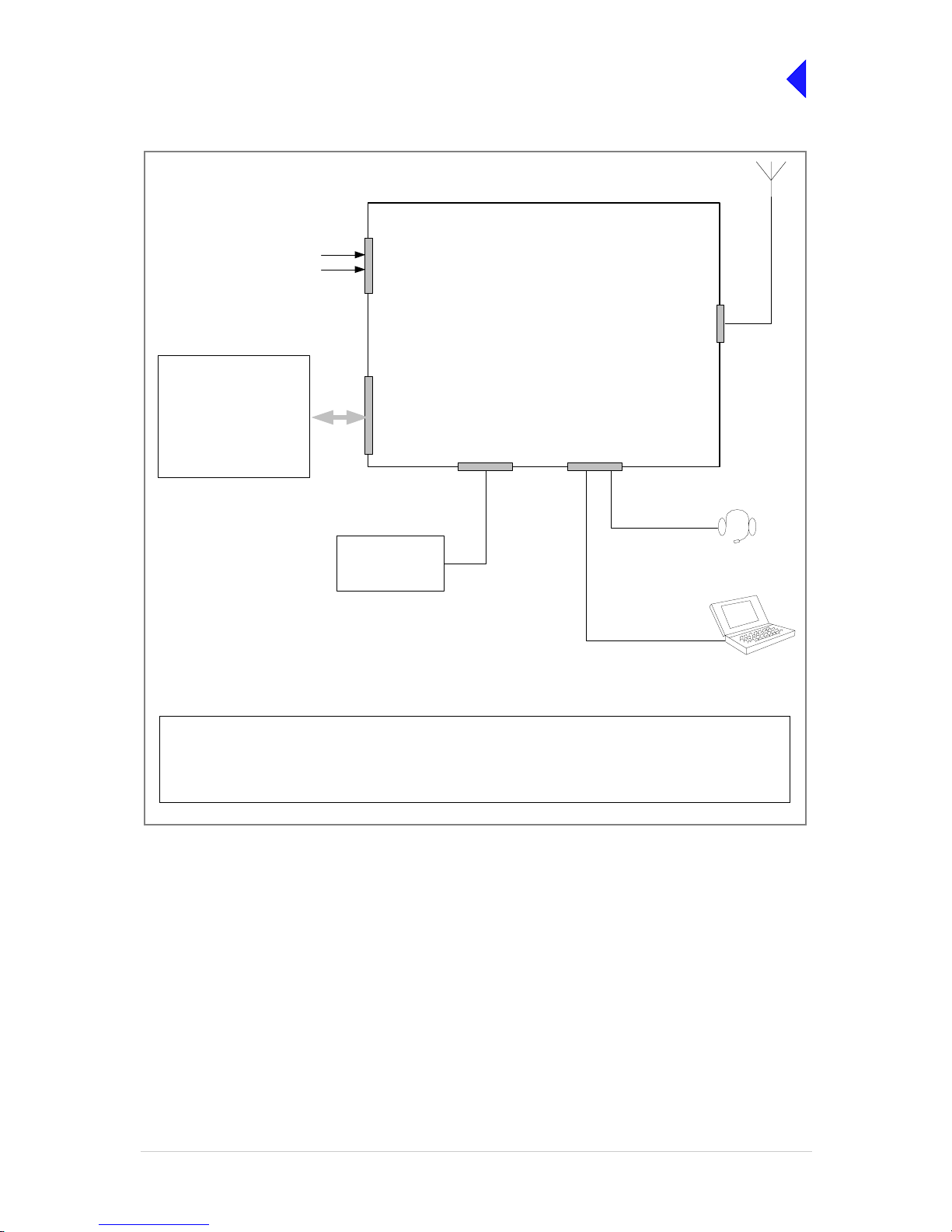
Fig 1 T6T Transmitter Configured for Local Operation
For local operation, the transmitter is operated from the front panel using a microphone/headset.
Any of the optional facilities may be connected.
Antenna
Connector
Reference
Connector
Microphone/Diagnostics
Connector
Frequency Counter
required only for
maintenance
Facilities
Connector
T6T Transmitter
E-BIT input
PTT relay output
External VSWR input
dc supply output
Inhibit input
BIT interr uptive test in put
Antenna change-over output
Ready output
Tape output
Optional Facilities that
can be used if required
Laptop (or PC) required
only for maintenance
Mic/Headset for
local operation
Page 59
T6T VHF 100 W Transmitter Page 5 Installation
Back to Transmitter
Main Page
Fig 2 T6T Transmitter Configured for Remote Operation
For remote operation, Audio and PTT signals from the control equipment terminate on the MARC
connector, or alternat ively o n the MARC Audio conn ector. If data is re quired by a compati ble data system ,
the RS422 data lines terminate on the MARC connector, or alternatively on the MARC Data connector.
Any of the optional facilities may be connected.
Antenna
Connector
Microphone/Diagnostics
Connector
MARC Connector
or,
MARC Audio Connector
Mic/Headset for
engineering use
Laptop (or PC) required
only for maintenance
T6T Transmitter
Optional Facilities that
can be used if required
E-BIT input
PTT relay output
External VSWR input
dc supply output
Inhibit input
BIT interruptive test input
Antenna change-over output
Ready output
Tape output
Reference
Connector
Frequency Counter
required only for
maintenance
Facilities
Connector
Audio
PTT
Page 60

T6T VHF 100 W Transmitter Page 6 Installation
Back to Transmitter
Main Page
Fig 3 T6T Transmitter Configured for use with MARC
When using a T6T transmitter with a MARC Remote Site Equipment (RSE2) the transmitter MARC
connector is pin-to-pin wired to one of the RSE2 Equipment connectors.
Any of the optional facilities may be connected.
Antenna
Connector
Reference
Connector
Microphone/Diagnostics
Connector
T6T Transmitter
Equipment
Connector
RSE2
MARC
Connector
Audio
PTT
RS422 data
dc supply ou tput
E-BIT input
PTT relay output
External VSWR input
Unregulated supply output
Inhibit input
BIT interruptive test input
Antenna change-ov er output
Ready outp ut
Tape output
Facilities
Connector
Frequency Counter
required only for
maintenance
Mic/Headset for
engineering use
Laptop (or PC) required
only for maintenance
Optional Facilities that
can be used if required
Page 61

T6T VHF 100 W Transmitter Page 7 Installation
Back to Transmitter
Main Page
Fig 4 T6T Transmitter Mode 2 Configuration
Antenna
Connector
T6R Receiver
Antenna
Connector
T6T Transmitter
HDLC
Connector
T1/E1
Connector
Facilities
Connector
Reference
Connector
Microphone/Diagnostics
Connector
Reference
Connector
Headset/Diagnostics
Connector
T1/E1
Connector
Fast Antenna
Change-Over
Switch
Antenna c/o control
Mode 2
Network Computer
Laptop (or PC) required
only for maintenance
Connects to the
Microphone/Diagnostics
connector
Frequency Counter
required only for
maintenance
Connects to the
Reference connector
Control and data
Control and
data. 2 km
maximum
distance
Page 62

T6T VHF 100 W Transmitter Page 8 Installation
Back to Transmitter
Main Page
Fig 5 T6T Transmitter Mode 3 Configuration
Antenna
Connector
T6T Trans m itter
T1/E1
Connector
Reference
Connector
Microphone/Diagnostics
Connector
Mode 3
Network Computer
Control and data
Frequency Counter
required only for
maintenance
Laptop (or PC) required
only for maintenance
Page 63

T6T VHF 100 W Transmitter Page 9 Installation
Back to Transmitter
Main Page
Installation Procedures
Initial Inspection of the Transmitter
On receipt of the transmitter, remove all transit packaging and check that there is no damage. If damage
is evident, contact Park Air immediately and retain the original transit packaging. One copy of the T6 User
Documentation CD (part number 31-36T62VCD) is normally supplied with the transmitter. This CD
includes the VFP software.
Fitting the Correct AC Input Fuses
The mains input fuses, F3 and F4, are an integral par t of the rear panel ac con nectors. The fuse type
must be correct for the local mains supply as detailed below.
Fitting a Radio into an Equipment Cabinet
It is essential that the chosen mechanical installation provides adequa te support along the
depth (front to rear) of the unit. The transmitter must not be supported by the front panel;
doing so can cause damage.
The transmitter ca n be installed on telescopic slides, or on fixed runner s, within a standard 483 mm
(19 inch) equipment cabinet. M4 tapped holes, each 10 mm deep (see Fig 6) are provided on each side
of the equipment to accept the slides. Details of suitable telescopic slides and fixed runners are available
from Park Air.
When fitted in the cabinet, the transmitter's fr ont panel must be sec ured to the cabinet’s chassis usi ng
four M6 x 16 mm screws and plastic washers.
FS2
Spare Fuse
Line
Neutral
Earth
For a mains input in the range 110 to 120 Vac, fuses
F3 and F4 should be rated T4A, 125V, UL.
For a mains input in the range 220 to 230 Vac, fuses
F3 and F4 should be rated T4A, 250V, IEC.
F3 and F4
Holder for spare
fuse (not supplied)
Caution Mechanical Support
Page 64

T6T VHF 100 W Transmitter Page 10 Installation
Back to Transmitter
Main Page
Fig 6 Slide Fittings
Make External Signal Connections
Making the external si gn al c onn ec tio ns i nv olv es configuring the transmit ter to su it its operational mode.
Illustrations showing various configurations are shown in Fig 1 to Fig 5; these figures should be used only
as a guide.
Front Panel Connectors
The front panel has two connectors; Microphone/Diagnostics and Reference connectors. These are
illustrated in Fig 7.
Fig 7 Front Panel
3
4
2
1
M4 x 8 mm Half Head Bolt
M4 Wavy Washer
Inner Slide
Transmitter
Description
4
3
2
1
Item
Page 65

T6T VHF 100 W Transmitter Page 11 Installation
Back to Transmitter
Main Page
Microphone/Diagnostics Connector
The Microphone/Diagnostics connector is a self-locking 7-way DIN socket used for connecting a
microphone, microphone/headset or PC. The connector pin-out is detailed in Table 3.
Reference Connector
The Reference connector is an SMB plug used to moni tor the radio’s referen ce frequency. It monit ors
the frequency at a level of 100 mV (±50 mV) with less than -10 dBc harmonics.
Table 3 Microphone/Diagnostics Connector
Pin Number Signal Characteristic Usage
1 Microphone ground 0 V. M ic roph one /H ea dse t
2 Transmit data RS232. 115200 baud, 8 data bits, 1 stop bit,
no parity, no handshaking.
PC
3 Microphone PTT 0 V to PTT. Microphone/Headset
4 Receive data RS232. 115200 baud, 8 dat a bit s , 1stop bit,
no parity, no handshaking.
PC
5 Sidetone – Microphone/Headset
6 Microphone input To ensure correct VOGAD operation, the
following microphone input levels are
required:
Passive setting: between 2 and 35 mV
Active setting: between 8 and 140 mV.
Microphone/Headset
7Ground 0V. PC
Pin-out of the Microphone/Diagnostics connector looking into
the mating face of the chassis mounted socket.
A suitable free socket is detailed in Table 2 on page 3.
Page 66

T6T VHF 100 W Transmitter Page 12 Installation
Back to Transmitter
Main Page
Rear Panel Connectors
The rear panel con nector s a re shown in F ig 8 and listed in T able 4. Select whi ch c onnec tors are goi ng
to be used and then make connections as required.
Fig 8 Rear Panel (Connectors)
Table 4 Rear Panel Connector Usage
Connector Type Usage
AC supply 2 x IEC Terminating the ac input supply.
DC supply 2 x XLR 3-pin Terminating the dc input supply.
Antenna N-type Terminating the antenna feeder coaxial cable.
External speaker 3.5 mm stereo jack Connects an external loudspeaker for monitoring sidetone.
MARC 9-way D-type Used to connect to a MARC remote site equipment.
Used to connect a T6 controller or hub.
Used to terminate remote audio and PTT signals when a
remote site equipment or T6 controller is not used.
MARC audio RJ48 Used as an alternative to the MAR C conn ector fo r terminati ng
remote audio and PTT signals.
MARC data RJ48 Used as an alternative to the MARC connec tor for termin ating
data signals to and from a compatible data system.
Facilities 15-way D-type Provides a number of optional facilities that can be used as
required.
T1/E1 RJ48 Used for connecting the radio to a Mode 3 network computer,
connecting a transmitter and receiver together as a Mode 2
base station, or for connecting to a digital voice and data
network.
HLDC RJ48 Used to connect to a Mode 2 network computer.
RF VOLTAGES
DANGER HIGH
ANTENNA
CONNECT
ANTENNA
BEFORE
USE
F15A 32V
110-240V T4A 250V IEC
110-120V T4A 125V U L
FUSE F1 / F2
FUSE F3 / F4
SEE INSTALLATION INSTRUCTIONS BEFORE
DISCONNECT SUPPLIES WHEN NOT IN USE
DC SUPPLY
CONNECTING SUPPLIES
21.6-32V 28 A
RATINGS
POWER 800VA max
AC SUPPLY
48-62Hz
FUSE F2
FUSE F1
+
-
+
-
DC SUPPLIES
~ AC SUPPLIES
FUSE F4FUSE F3
FACILITI ES
SUPPLY
MARC
AUDIO
T1 / E1 HDLC
DATA
MARC
MARC
DANGER HIGH
RF VOLTAGES
USE
BEFORE
CONNECT
USE
DANGER HIGH
RF VOLTAGES
CONNECT
BEFORE
Page 67

T6T VHF 100 W Transmitter Page 13 Installation
Back to Transmitter
Main Page
MARC Connector
The MARC connector is a 9-way D- type soc ket used t o conne ct the transm itt er to a MARC r emote site
equipment, or it can also be used for normal remote operation.
As an alternative to using this conn ector, the RJ 48 styl e MARC Audi o and MARC Data connector s can
be used to provide the same functions.
The MARC connector pin-out is shown below and detailed in Table 5.
Note ...
The line level figures shown for the MARC connector are the limits when testing the transmitter using
a sine wave; the li ne level w ill be 10 dB above th e line level setting. Se e the infor mation supp lied
under the heading ‘Line Level Setting’ in Operation.
Table 5 MARC Connector
Pin Number Signal Characteristic
1Ground 0V.
2
3
Audio line in (+)
Audio line in (-)
Balanced 600 ohm, -20 to +20 dBm.
Phantom keying can be superimposed on the audio
lines. See Fig 10.
4 PTT input
Remote PTT signal input. See Fig 9.
5 Output supply This output is between 21.6 and 32 Vdc (nominally
28 V) fused at 500 mA.
6
7
Data in (+)
Data in (-)
RS422 differential asynchronous data at 9600 baud,
8 data bits, 1 stop bit, no parity, no handshaking.
8
9
Data out (+)
Data out (-)
RS422 differential asynchronous data at 9600 baud,
8 data bits, 1 stop bit, no parity, no handshaking.
Pin-out of MARC conne ctor l ookin g into the m ating f ace o f the
chassis mounte d socket.
A suitable free socket is detailed in Table 2 on page 3.
15
69
Page 68

T6T VHF 100 W Transmitter Page 14 Installation
Back to Transmitter
Main Page
MARC Audio Connector
The MARC Audio co nnector is an 8-way RJ48 so cket. It can be used as an alternative to the MARC
connector for audio and PTT connections. The connector pin-out is shown below and detailed in Table 6.
Note ...
The line level figures shown for the MARC Audio connector are the limits when testing the
transmitter using a sine wave; the line level will be 10 dB above the line level setting. See the
information supplied under the heading ‘Line Level Setting’ in Operation.
Table 6 MARC Audio Connector
Pin Number Signal Characteristic
1
2
Audio line in (-)
Audio line in (+)
Balanced 600 ohm, -20 to +20 dBm.
Phantom keying can be superimposed on the audio
lines. See Fig 10.
3 Fast antenna
change-over/PTT
(output)
Open collector NPN transistor grounding output,
200 mA max, configurable n/o or n/c.
4 Not used 5 Not used 6 PTT (input) Remote PTT signal input. See Fig 9.
7 Ground 0 V.
8 Not used -
Pin 1
RJ48 Plug
Numbering is shown looking from the top of the connector.
The top is being viewed when the lever is on the bottom.
Page 69

T6T VHF 100 W Transmitter Page 15 Installation
Back to Transmitter
Main Page
Fig 9 Remote Keying
Fig 10 Phantom Keying
T6T Transmi tt e r
MARC Audio Connector
Audio is pins 1 and 2.
Audio line 1
Audio line 2
PTT
Reference Voltage
(0 V, +14 V or -14 V)
Set from front panel
PTT
Switch
V
PTT
The transmitter reference voltage (0 V, +14 V or -14 V) is selected from the Polarities screen:
❑ PTT is active when V
PTT
differs from the transmitter reference voltage by more than ±10 V.
❑ PTT is inactive when V
PTT
differs from the transmitter reference voltage by less than ±1 V.
❑ Maximum value of V
PTT
is ±60 V with respect to transmitter reference voltage.
Example:
To use 0 V as the keying potential, V
PTT
= 0 V; set transmitter reference voltage to +14 V; set PTT In to STD.
Cross-Site Lines
Audio
Circuit
PTT input requires at least 1 mA to operat e.
Input will draw no more than 6 mA.
PTT is pin 6
MARC Connector
Audio is pins 2 and 3.
PTT is pin 4
MARC or
MARC Audio
Connector
Control
Equipment
Ground is pi n 7.
Ground is pin 1.
T6T Transmitter
PTT
Switch
Reference Voltage
(0 V, +14 V or -14 V)
Set from front panel
V
PTT
To reduce the number of cross-site lines between the control site and the transmitter, phantom key ing may be employed.
This method has the keying potential (V
PTT
) superimposed on the audio lines instead of using a separate line.
The transmitter reference voltage (0 V, +14 V or -14 V) is selected from the Polarities screen:
❑ PTT is active when V
PTT
differs from the transmitter reference voltage by more than ±10 V.
❑ PTT is inactive when V
PTT
differs from the transmitter reference voltage by less than ±1 V.
❑ Maximum value of V
PTT
is ±60 V with respect to transmitter reference voltage.
Example:
To use 0 V as the keying potential, V
PTT
= 0 V; set transmitter reference voltage to +14 V; set PTT In to STD.
Audio lines with phantom keying
signal superimposed
PTT input re quires at least 1 mA to operate.
Input will draw no more than 6 mA.
MARC Audio Connector
Audio is pins 1 and 2
MARC Connector
Audio is pins 2 and 3
MARC or
MARC Audio
Connector
Audio
Circuit
Control
Equipment
Page 70

T6T VHF 100 W Transmitter Page 16 Installation
Back to Transmitter
Main Page
MARC Data Connector
The MARC Data conne ctor is an 8-way RJ48 socke t. It can be used as an alt ernative to the MARC
connector for data connections. The connector pin-out is shown below and detailed in Table 7.
Ta ble 7 MARC RJ48 Data Connector
Pin Number Signal Characteristic
1
2
Data in (-)
Data in (+)
RS422 differential asynchronous data, 9600 baud,
8 data bits, 1 stop bit, no par ity, no handshaking.
3 Not connected 4
5
Data out (+)
Data out (-)
RS422 differential asynchronous data, 9600 baud,
8 data bits, 1 stop bit, no par ity, no handshaking.
6 Remote supply ON/OFF 0 V to switch off.
Note: Rear panel switch must be in the ON position
for this function to operate.
7Ground 0V.
8 Output supply This output is between 21.6 and 32 Vdc (nominally
28 V) fused at 500 mA.
Pin 1
RJ48 Plug
Numbering is shown looking from the top of the connector.
The top is being viewed when the lever is on the bottom.
Page 71

T6T VHF 100 W Transmitter Page 17 Installation
Back to Transmitter
Main Page
T1/E1 Connector
The T1/E1 connector is an 8- way RJ48 socket used for conn ecting to a Mode 3 network computer or
connecting a transmitter and receiver together when operating as a Mode 2 base station. The connector
pin-out is detailed in Table 8.
Table 8 T1/E1 Connector
Pin Signal Characteristic
1 RRing T1 - Balanced 100 ohm (±10%), 1.544 Mbits per second (±50 ppm), AMI/B8ZS Coding.
E1 - Balanced 120 ohm (±10%), 2.048 Mb it s p er s ec on d (±50 ppm), AMI/HDB3 Codi ng.
Protected with 28 V differential and common mode clamp and 1.25 A fuse in each line.
2RTip
3 Not connected 4 TRing T1 - Balanced 100 ohm (±10%), 1.544 Mbits per second (±50 ppm), AMI/B8ZS Coding.
E1 - Balanced 120 ohm (±10%), 2.048 Mb it s p er s ec on d (±50 ppm), AMI/HDB3 Codi ng.
Protected with 28 V differential and common mode clamp and 1.25 A fuse in each line.
5TTip
6 Not connected 7 Not connected 8 Not connected -
Pin 1
RJ48 Plug
Numbering is shown looking from the top of the connector.
The top is being viewed when the lever is on the bottom.
Page 72
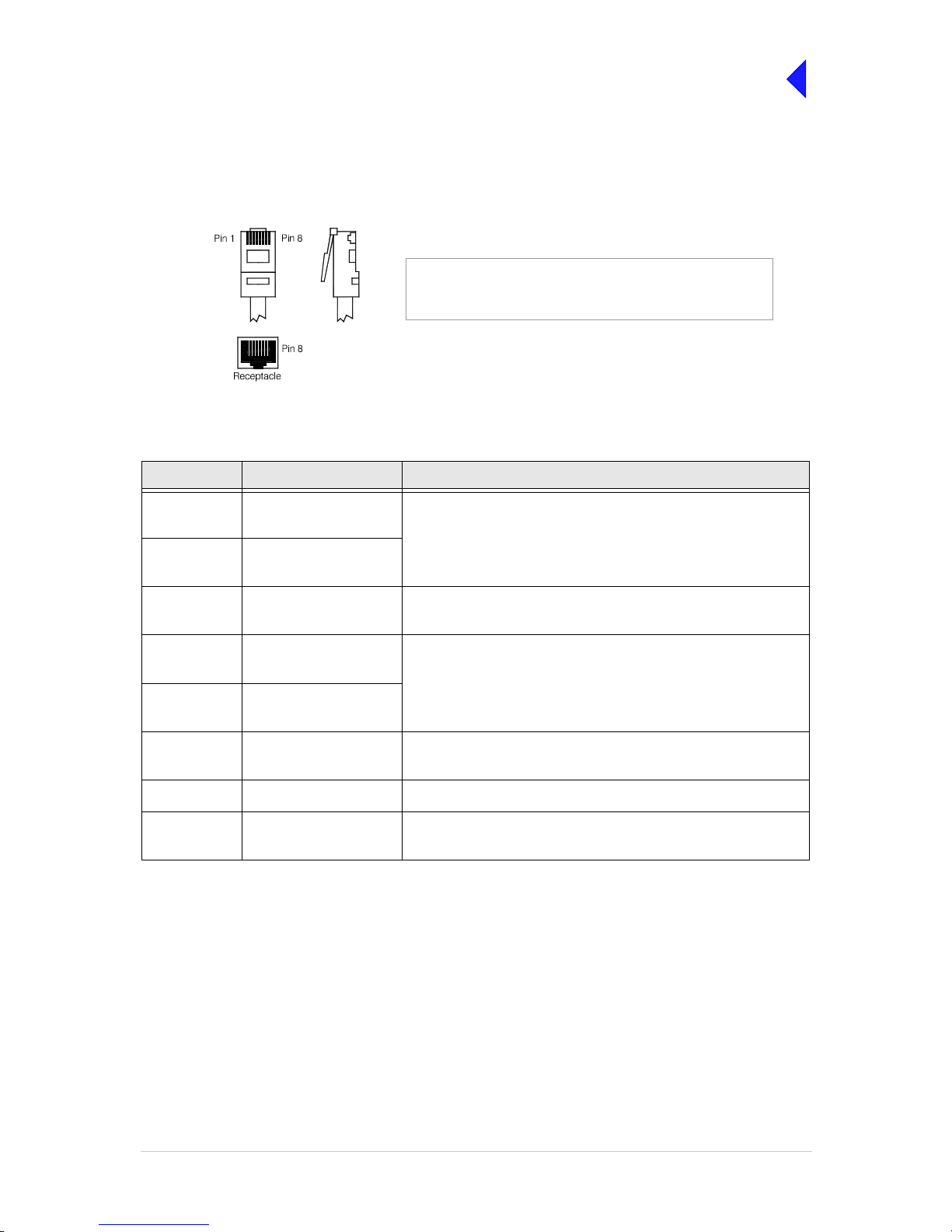
T6T VHF 100 W Transmitter Page 18 Installation
Back to Transmitter
Main Page
HDLC Connector
The HDLC connector is an 8-way RJ48 socket used for connecting to a Mode 2 network computer. The
connector pin-out is detailed in Table 9.
.
Ta ble 9 HDLC Connector
Pin Signal Characteristic
1 HDLC RX A
(input)
RS422 differential synchronous data, 128 kbytes per second
(±50 ppm).
2 HDLC RX B
(input)
3 HDLC CL A
(output)
RS422 differential synchronous data, 128 kbytes per second
(±50 ppm).
4 HDLC TX B
(output)
RS422 differential synchronous data, 128 kbytes per second
(±50 ppm).
5 HDLC TX A
(output)
6 HDLC CL B
(output)
Pair to pin 3.
7Ground 0 V.
8 Output supply This output is between 21.6 and 32 Vdc (nominally 28 V) fused at
500 mA.
Pin 1
RJ48 Plug
Numbering is shown looking from the top of the connector.
The top is being viewed when the lever is on the bottom.
Page 73

T6T VHF 100 W Transmitter Page 19 Installation
Back to Transmitter
Main Page
External Speaker
The External Speaker connector is a 3.5 mm stereo jack used for connecting an external speaker to the
transmitter to provide sidetone. This speaker should be a high impedance active type.
Table 10 External Speaker
Pin Signal Characteristic
Tip Speaker drive (output) 0 to 3 V pk-pk. Connected directly to Ring.
Ring Speaker drive (output) 0 to 3 V pk-pk. Connected directly to Tip.
Sleeve Ground 0 V.
Page 74

T6T VHF 100 W Transmitter Page 20 Installation
Back to Transmitter
Main Page
Facilities Connector
The Facilities conne ctor i s a 15-w ay D-t ype filter ed s ocket us ed for connec ting to as soc iated pa rts of a
system. The connector pin-out is detailed in Table 11.
Table 11 Facilities Connector
Pin Number Signal Characteristic
1Ground 0V.
2 E-BIT (input) An external BIT input that connects from any ancillary equipment
having a compatible BIT alarm output.
When this input is active, the transmitter’s front panel Alarm indicator
flashes and an E-BIT message is dis played on the dis play . The in put is
TTL having a 4.7 kohm pull-up resistor to 5V. The input is
configurable from the front panel to be active high or low.
3 PTT output Grounding solid state relay. +60 to -60 V, ac or dc, 100 mA max,
configurable n/o or n/c. Activated 35 ms (±1 ms) before the start of the
power ramp up to allow for the antenna relay pull-in time.
4 External VSWR input Used to indicate an externa l VSWR fa ult. TTL input with 4.7 kohm p ull-
up to 5 V. Configurable active high or low.
5
6
Antenna change-over
(output)
Antenna change-over
common (output)
Solid state relay linked to pin 6. See Fig 11 for further detail.
Solid state relay linked to pin 5.
7 Not used 8Ground 0 V.
9 Output supply This output is between 21.6 and 32 Vdc (nominally 28 V) fused at
500 mA.
10 Inhibit (input) Active signal prevents the transmitter keying. TTL with 4.7 kohm pull-
up to 5 V. Configurable active high or low.
11 BIT interruptive test
(input)
Active signal initiates a BIT test. TTL with 4.7 kohm pull-up to 5 V.
Configurable active high or low. Must be asserted for >300 ms.
12 Not used 13 Ready (output) An output that is active when the radio is ready to transmit and no
faults are detected. Open collector NPN transistor grounding output,
200 mA max, configurable n/o or n/c.
14 Tape (output) An audio output for connection to a recording system. 0 dBm fixed
output into 600 ohm for 90% modulation depth.
15 Reserved (output) Do not connect to pin 15 unless advised to do so by Park Air.
18
915
Pin-out of Facilities connector looking into the mating face of
the chassis mou nted socket.
A suitable free socket is detailed in Table2 on page 3.
Page 75

T6T VHF 100 W Transmitter Page 21 Installation
Back to Transmitter
Main Page
Fig 11 Example: Using the Antenna Change-over Output
T6T Transmitter
6
5
Facilities
Connector
Antenna
T6T Transmitter
Facilities
Connector
Antenna
9
28 Vdc (nominal)
Control
(Main)
(Standby)
Antenna
Main/Standby
Transmit Relay
Example
This example shows the Antenna Change-over Output configured to control the antenna switching between main
and standby transmitters. The potential on Facilities connector pin 6 is switched through to pin 5 when the standby
transmitter is keyed; in this example, pin 6 is linked to ground. This energizes the Main/Standby Transmit Relay to
route the standby transmitter to the antenna.
Other Configurations
The antenna change-over output can be configured in other ways to suit the user’s requirement subject to:
❑ Pin 6 can be any potential between -60 and +60 Vac, or dc.
❑ The maximum current drawn must not exceed 100 mA.
❑ The output at pin 5 is configurable normally open or normally closed from the Polarities screen.
❑ The internal solid state switch activates 35 ms before the start of the power ramp to allow for the antenna
relay pull-in time.
8
Solid State
Relay
Link
Page 76

T6T VHF 100 W Transmitter Page 22 Installation
Back to Transmitter
Main Page
Chassis Stud Connection
A chassis stud is fitted to the transmitter's rear panel. This stud is used to connect the
equipment to the equipment cabinet, or to the user's system earth point. The stud must not
be used as the safety earth.
In order not to compromise the transmitter’s Electromagnetic Compatibility (EMC) the chassis stud,
marked and fitted to the rear panel must be connected to the equipment cabinet (if a cabinet is being
used) or to the user's system earth point. The connection should be made using a single tri-rated, greenand-yellow cable having a cross-section al area of 2 .5 mm
2
. The cable should have CSA an d UL1015
approval, and be connected to the chassis stud through an M6 eyelet (for example, Park Air part number
20-08010103).
Failure to comply with this instruction could result in non-compliance with the European
Commission EMC Directive 89/336/EEC.
Connect the Antenna
The antenna connector is an N-type socket suitable for connecting a 50 ohm antenna.
Connect the DC Input Supply
The transmitter o perates from e ither an a c, or a dc inpu t su pply. When both ac and dc are connecte d,
operation from the ac supply takes priority; automat ic change-over to the dc supply occurs if the ac
supply fails. On restoration of the ac supply, the equipment reverts to ac operation.
The dc input supply conne ctors (see Fig 12) are fitted to the transmitte r rear panel. T he recommend ed
minimum rating of the dc supply cables is: 2-core having a cross-sectional area of 1.5 mm
2
per core. The
supply cables should be fitted with XLR 3-pin connectors (Park Air part number 20-01030106).
Fig 12 DC Connectors
WARNING Chassis Earth
Positive Negative
Not used
Pin-out of DC connector looking
into the mating face of the chassis
mounted socket.
Page 77

T6T VHF 100 W Transmitter Page 23 Installation
Back to Transmitter
Main Page
Connect the AC Input Supply
The equipment is permanently connected to the mains supply when the mains connector is
attached. Switching the rear pan el Power switch to off does not isolate all internal circuits
from the mains supply. For this reason, a mains isolating switch should be fitted close to,
and easily accessible from, the transmitter's position. The isolation switch should isolate
both live and neutral supplies, be clearly labelled, and adequately rated to protect the
equipment.
This equipment must be earthed. The earth terminal of the ac connector should be used as
the safety earth.
Two ac input connectors are fitted to the transmitter rear panel. The cables used to connect between the
equipment and the ac power source should be 3-core (to IEC 227) rated 250 Vac at 8 amps, and have a
minimum cross-s ectio nal a rea of 1.0 mm
2
per core. Park Air recommends the use of polyviny l chloride
(PVC) insulated cable. The cable must be fitted with the IEC approved equipment connector and conform
to the following specification:
❑ If PVC insulated, be not li ghter than ordinary po lyvinyl c hloride sh eathed flex ible cord ac cording
to IEC publication 227 (designation H05 VV-F, or H05 VVH2-F).
❑ If rubber insulated, be of synthetic rubber and n ot lighter than ordinary toug h rubber-sheathed
flexible cord accordin g to IEC publi cation 24 5 titled ‘Rub ber Insulate d Cables of Rated V oltage s
up to and Including 450/750 V (designation H05 RR-F)’.
The T6T 100 W transm itter is a Class 1 equipment. The ac supply cables should have a green-andyellow protective earthing conductor electrically connected to the protective earthing terminal of the
equipment connector a nd the ma ins p lug. Par k Air recomm ends the ac supp ly c able is colo ur code d in
accordance with the electrical appliance (colour code) regulations for the UK. That is:
WARNING Dangerous Voltages
WARNING Earth Connection
FS2
Spare Fuse
Line
Neutral
Earth
❑ The core coloured green-and-yellow must be
connected to the terminal in the plug that is
marked with the letter E or by the earth symbol
or coloured green-and-yellow.
❑ The core coloured blue must be connected to
the terminal that is marked with the le tter N or
coloured black.
❑ The core coloured brown must be connected to
the terminal that is marked with the letter L or
coloured red.
F3 and F4
Page 78

T6T VHF 100 W Transmitter Page 24 Installation
Back to Transmitter
Main Page
Switching On
When the Power switch is set to the Standby position, dangerous voltages are still present
in the transmitter's internal power supply circuitry. To ensure safe working, the transmitter
must be isolated from the ac and dc input supplies.
When installation is complete, the transmitter should be swit ched on at the rear panel 2-way rocker
Power switch. The Power switch is used to switch on, and switch off, power to the transmi tte r's circui tr y
but does not remove power from the radio.
Under normal circumstances this screen is displayed for a few seconds when the radio is switched on.
The bottom row begins empty and dots are added as the initialisation progresses. When the initialisation
is complete the Main Screen is displayed.
Setting Up
When installation ha s b een s uc c essfu ll y c om ple ted the tr an sm itter must be set up using th e fr ont pane l
controls or the VFP.
Setting up is detailed in the Operation section of this documentation.
T 6 D i g i t a l R a d i o
( c ) 2 0 0 3 P a r k A i r
I n i t i a l i s i n g . . . .
. . . . . . . . . . . . . . .
WARNING
Dangerous Voltages
= Standby= On
When setting up the tra nsmitter, pay particular attention to t he Polarities of any
functions that have been hardwired during installation. For example, the polarity of
the PTT input and the polarity and configuration of the Antenna Change-over
output. Failure to select the correct settings will result in incorrect operation.
Page 79

Back to Transmitter
Main Page
Maintenance
This topic gives scheduled maintenance procedures, details module replacement, and
describes h ow to use the Virtual Front Panel (VFP).
Page 80

T6T VHF 100 W Transmitter Page 2 Maintenance
Back to Transmitter
Main Page
Introduction
This section gives the scheduled and unscheduled maintenance procedures for the T6T 100 W
transmitter and shows how to use the Virtual Front Panel (VFP).
Configuration
T6 radios are configured in respect of hardware and software.
Hardware Configuration
The radio’s hardware configuration is identified by the
modification leve l. A modificatio n label is fitted to the radio’s
rear panel showing the model of radio, the radio’s part number
and the radio’s serial number.
The modification (Mod) record shows the configuration status.
In the example shown, the radio is at Mod strike 8.
Modification Label
Software Configuration
A white label fitted to the top
cover lists the radio’s software
configuration.
In this example there are three
fills: AM-Voice, Mode 2 and
Mode 3.
Software Configuration Label
Replacement Modules
To ensure compatibi li ty when repl ac in g a ra dio or a mod ule , th e c onfi gu ration should be the sam e (s ee
the previous headings: Hardware and Software Configuration).
Spare modules received from Park Air are supplied with a Spares Instruction that details the
configuration of the module and any special instructions. If in any doubt regarding the suitability of spare
modules contact Park Air Customer Support.
Scheduled Maintenance A scheduled maintenance procedure is given on page 3. Park Air
recommends that this task be completed every twelve months.
Unscheduled Maintenance Normally, the T6 transm itter i s con sidere d a Li ne Repl aceabl e Un it
(LRU) and should be replaced with a serviceable spare if a fault
occurs. The faulty transmitter should then be returned to Park Air
for repair.
In certain circumstances, Park Air Customer Support may suggest
that the user change one of the transmitter modules. Dismantling
and assembly instructions are therefore given under the heading
Unscheduled Maintenance starting on page 7.
Using the VFP Operating parameters can be set from the transmitter front panel,
or by using the VFP. Some additional functions are available from
the VFP. See page 22.
T6T100
B63100HS/NB
2K1234
Software Configuration
Part Order No. B63100HS/NB
Software Mode Part No.
Fill 1 AM_VOICE 65-00000465
Fill 2 2 65-00000466
Fill 3 3 65-00000467
Fill 4
2K1234
Page 81

T6T VHF 100 W Transmitter Page 3 Maintenance
Back to Transmitter
Main Page
Scheduled Maintenance
Park Air recommends that scheduled maintenance is carried out at twelve-monthly intervals. Scheduled
maintenance comprises the following checks:
Cleaning and Checking Security of Connectors
Remove all dust and dirt from the equipment exterior using a lint-free cloth and camel hair brush. Check
all external connections are secure and free from damage.
Setting the Transmitter Internal Reference Frequency
To set the transmitter internal reference frequency, use the following procedure. Note that references to
the switch in the procedure mean the Scroll/Select switch.
(6) Turn the switch clockwise until Exit is highlighted, then press the switch. You are returned to the
Main screen.
(7) Disconnect the frequency counter.
Number Check Tools/Test Equipment Required
1 Ensure the equipment is clean and that external
connectors are securely fitted.
Camel hair brush/clean lint-free
cloths
2 Check and reset (if required) the transmitter’s
internal frequency reference.
VHF frequency counter
3 Perform a BIT interruptive test.
4 Perform an ac and dc change-over check (if both
supplies are connected).
Control Screen
Settings Screen
F r e q u e n c y
C h a n n e l
S e t t i n g s
E x i t
B a n d E d g e s
R e f F r e q 5 0 . 0 %
B a c k l i g h t 0 3 0 s
E x i t < < > >
(1) Ensure the transmitter does not have
an offset.
(2) Connect a frequency counter to the
front panel Reference connector.
(3) From the Main screen, press th e swit ch
to display the Contro l screen. Tur n the
switch until Settings is highlighted.
Press the switch.
(4) Ensure the Settings screen is
displayed. Turn the switch until Ref
Freq is highlighted, then press the
switch.
(5) With Ref Freq select ed turn the switch
clockwise or anti-clockwise until the
frequency counter reads
20.950000 MHz ±10 Hz, then press the
switch.
Page 82

T6T VHF 100 W Transmitter Page 4 Maintenance
Back to Transmitter
Main Page
(8) If not using 5-carrier offset, refer to AM-Voice Mode Settings Screen in the Operation section of
this document and set to the required offset.
(9) If 5-carrier offset is required, restore the carrier offset using the following routine:
❑ Connect a 50 ohm frequ ency counter, through a 60 dB atten uator, to the transmitter rear
panel Antenna connector (see Fig 5 for location of the Antenna connector)
❑ Refer to AM-Voice Mode Settin gs Scre en in the O peration sectio n of this do cumen t and set
the desired 5-carrier offset
❑ Refer to Changing the Transmitter Operating Frequency in the Operation section and set the
transmitter to the neare st 2 5 k Hz ch ann el f re que ncy. F o r e xampl e, i f th e r equ ired frequency
is 124.504 (+4 kHz offset), set the transmitter to 124.500 MHz
❑ Key the transmitter and ad just the reference freque ncy, using the front panel S croll/Select
switch, until the frequency cou nter displays the required op erating frequenc y. For exampl e
124.504 MHz
❑ When the frequency counter displ ays the ex act operati ng freque ncy, press the Scroll /Selec t
switch and stop keying the transmitter
❑ Disconnect the test equipment and reconnect the antenna.
Page 83

T6T VHF 100 W Transmitter Page 5 Maintenance
Back to Transmitter
Main Page
To Initiate a BIT Test
An interruptive BIT test cannot be initiated in Mode 2 or Mode 3.
(1) From the Main screen, pr es s th e s witc h t o
display the Control screen. Turn the switch
until BIT is highlighted. Press the switch.
(2) Ensure the BIT menu is displayed. Turn
the switch until BIT Ini tiate is highlighted.
Press the switch.
(3) During the test, which takes approximately
two seconds, the Testing screen is
displayed.
(4) After the test, either a Pass or Fail scr een
is displayed. Selecting OK takes the user
back to the BIT screen.
(5) If fail is displayed, scroll t hrough the screen
to check the cause of the failure.
During an interruptive BIT t est, the transmi tter rad iates modula ted car rier w aves at the s et power .
Users should therefore obtain the necessary authority before initiating a test.
If the test is to be carried out with the antenna disconnected, ensure a load is fitted to the
transmitter’s Antenna connector.
In order to test the line input stages, an internally generated 1 kHz tone is injected into the line input
circuit. Any other audio present on the line input will cause the test to be inaccurate. Therefore the
transmitter MUST NOT be keyed during the test.
B I T
S / W C o n f i g
S t a n d b y
E x i t < <
B I T I n i t i a t e
E T I 0 0 0 0 0 : 0 0 h r s
A C S u p p l y O N
E x i t > >
T e s t i n g
P l e a s e W a i t
T e s t S t a t u s
P A S S
O K
T e s t S t a t u s
F A I L
O K
Page 84

T6T VHF 100 W Transmitter Page 6 Maintenance
Back to Transmitter
Main Page
AC and DC Change-over Check
If both ac and dc input supplies are connected to the transmitter, carry out the following check:
(1) Confirm that both ac and dc supplies are connected to the transmitter. Ensure that the rear panel
Power switch is set to the I (on) position.
(2) Confirm that the front panel Re ady indic ator is lit , the LCD is ill uminated, an d the transmi tter is
operational.
(3) Switch off the ac supply from its source.
(4) Check that the transmit ter continues to opera te correctly from the dc sup ply. If accessed, the
front panel BIT screen w ill show AC Suppl y as off, and DC Suppl y as on. The value of th e dc
supply is also shown.
Page 85

T6T VHF 100 W Transmitter Page 7 Maintenance
Back to Transmitter
Main Page
Unscheduled Maintenance
The instructions given in this section involve connecting dangerous voltages to the
transmitter. Maintenance should be carried out only by suitably qualified personnel.
When an ac supply is connected, dangerous voltages are present within the transmitter. Care
must be taken by personnel to avoid accidental contact with exposed circuitry during
maintenance or alignment procedures.
When the Power switch is set to the Standby position, dangerous voltages are still present
in the transmitter's internal power supply circuitry. To ensure safe working, the ac and dc
input supplies must be disconnected from the transmitter.
The antenna used with the transmitter must be installed such that the resultant radiated field
strength is below 10 W/m² in areas normally accessible to personnel.
The T6 transmitter circuitry contains Electrostatic Sensitive Devices (ESSDs). Personnel
must be aware of the precautions necessary to prevent damage to such devices.
Changes or modifications made to this equipment that are not expressly approved by
Park Air, or parties authorized by Park Air, could void the user’s authority to operate the
equipment.
When carrying out repairs to the PA module, care must be taken not to damage the gasket.
If the strips become damaged, they must be replaced. Failure to comply with this instruction
may compromise the transmitter Electromagnetic Compatibility (EMC) and breach European
Commission regulations.
When screws are inserte d into th e trans mitter P A casting care mus t be tak en not to exceed
a torque of 6 Ibs/inch when tightening. This applies when replacing the top and bottom
covers and during the refitting of the PA modules.
WARNING Dangerous Voltages
WARNING
Antenna Radiation
Caution
ESSDs
Caution Unauthorized Modifications
Caution Repairs
Page 86
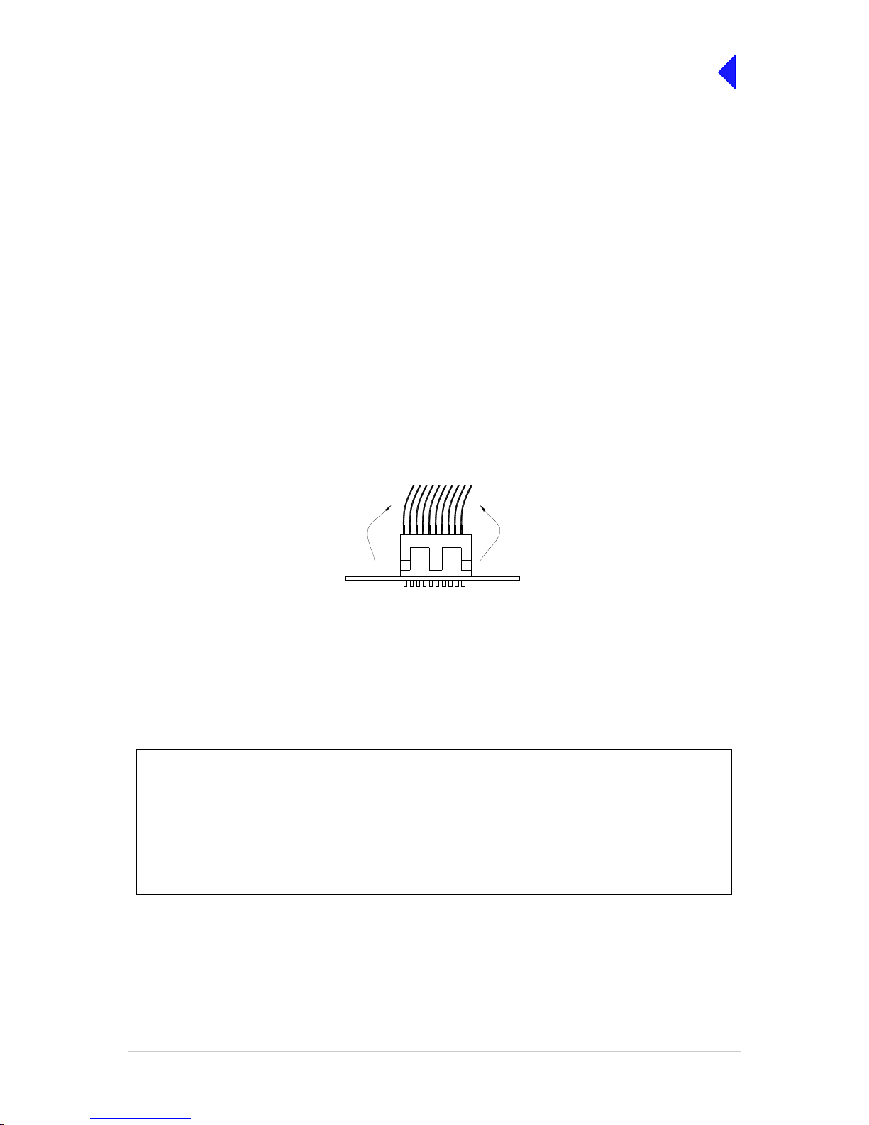
T6T VHF 100 W Transmitter Page 8 Maintenance
Back to Transmitter
Main Page
Introduction
This document provide s the use r with de tail ed ins tr uct io ns on the r emo va l and rep la cement of modules
and assemblies. When re moving or refitting modules , observe antistatic handling precautions. Do not
change any potentiom eter (or link) settings unless detaile d in these instructi ons. Potentiometers have
been set using specialist equipment.
Molex KK Connectors
The transmitter uses the following Molex KK connectors:
❑ CN2 on the PA Control module
❑ CN7 and CN6 on the PSU Regulator module.
To remove KK type connectors:
❑ Free the locking mechanism on the connector by moving one side of the connector up, then move
the other side up (see the following diagram). The upward motion should only be as far as needed
to free the locking mechanism
❑ DO NOT pull the cable to free the connector
❑ Note that KK type connecto rs are designed to be removed in this manner to free the locking
mechanism. Do not use this procedure with non-KK type connectors as damage to the connector
may occur.
Tools, Materials and Test Equipment Required
The following tools, materials and test equipment should be made available to complete the maintenance
tasks described in this section.
❑ Personal Computer (PC)
❑ General Purpose Tool Kit (including
a 1.5 mm Allen key)
❑ 5 mm Nut Spinner
❑ Camel Hair Brush
❑ Clean Lint-free Cloths
❑ Frequency Counter
❑ Power Meter
❑ Dummy Load
❑ PC to Radio Interconnection Lead
(Park Air part number 17E12600001)
❑ SMB to BNC Lead for Ref erence Frequency
(Park Air part number 17K11000004)
Lift 2Lift 1
PCB
Page 87

T6T VHF 100 W Transmitter Page 9 Maintenance
Back to Transmitter
Main Page
Top and Bottom Covers
One of the top cover screws is covered with a warranty l abel that sh ould not be tam pered with unless
Park Air Customer Su pport has advised otherwi se. When authorisation has been made the following
procedures should be followed.
To remove the to p cov er, lo ca te and unsc rew t he 19 count ersu nk scre ws se cu ring the top c over t o t he
mainframe. Access can then be gained to the Processor module and PSU Regulation module.
To remove the b ottom cover, locate and unscrew the 15 countersunk screws securing the bottom cover
to the mainframe. Access can then be gained to the PA Control module.
The following modules require both top and bottom covers to be removed:
❑ Power Supply modules
❑ Combiner BIT module
❑ PA modules
❑ Front Panel assembly PCB.
Removing and Refitting the Processor Module
The Processor module is located as shown in Fig 5. A module removal diagram is shown in Fig 8.
Dangerous voltages are present within the transmitter. Care must be taken by personnel to
avoid accidental contact with exposed circuitry when the covers are removed an d power is
applied to the radio.
Removal
Before attempting to remov e the Pr ocesso r modu le, and if pos sib le, save th e radio se ttings . Connect a
PC with the VFP software loaded to the radio using the PC to Radio Interconnection Lead (Park Air part
number 17E12600001). With the VFP software active, upload the radio settings to a specified file.
Ensure that the transmitter is isolated from the ac and dc input supplies. Then proceed as follows:
(1) Unscrew the 19 countersunk screws and remove the transmitter top cover.
(2) Locate the Processor module and disconnect the following connectors (Fig 8):
❑ CN1 50-way connector (50-way ribbon cable from PA Control module CN1)
❑ CN3 14-way connector (14-way ribbon cable from PSU Regulator module CN4)
❑ CN4 34-way connector (34-way ribbon cable from Front Panel module CN1).
(3) Gain access to th e rear of the transmitter. Using a 5 mm nut spinner tool, remove t he four
screwloc 8 mm-4-40 UNC stud spacers that secu re the Proces s or modul e i nte rface co nne ctors
CN5 and CN6 to the rear panel.
(4) Remove the seven M3 x 8 mm screws that secure the module to the transmitter mainframe.
(5) Remove the module from the chassis.
WARNING Dangerous Voltages
Page 88

T6T VHF 100 W Transmitter Page 10 Maintenance
Back to Transmitter
Main Page
Refitting
To refit the Processor module, proceed as follows:
(1) Place the module in position. E nsu re no wir es are tra ppe d by the mod ule . Ens ure ju mpe r J 2 on
the module is set to ‘T’ for transmitter (see Fig 1).
Fig 1 Processor Module JP2 Location
(2) Ensure the module interface connectors CN5 and CN6 are located correctly and are aligned with
the screw holes in the rear panel. Fit the four screwloc 8 mm-4-40 UNC screws and wavy
washers but leave them loose.
(3) Fit the seven M3 x 8 mm screws that secure the module to the transmitter mainframe, but leave
them loose.
(4) Using a 5 mm nut spin ner tool, tighten the four screwlo c 8 mm-4-40 UNC screws and wavy
washers that secure the connectors; then tighten the seven M3 x 8 mm screws that secure the
module to the transmitter mainframe.
(5) Refit the following connectors to the module:
❑ CN1 50-way connector (50-way ribbon cable from PA Control module CN1)
❑ CN3 14-way connector (14-way ribbon cable from PSU Regulator module CN4)
❑ CN4 34-way connector (34-way ribbon cable from Front Panel module CN1).
(6) Re-establish the ac and/or dc supplies.
(7) Switch power on at the radio using the rear mounted Power switch.
(8) Ensure the front panel Ready indicator is lit and the Alarm indicator is unlit.
(9) If a new module has been fitted, connect the VFP PC to the radio using the PC to Radio
Interconnection Lead, Park Air par t number 17 E12 600001 (if not alrea dy connec ted). Note that
any module sent from Park Air as a spare for a particular radio will be programmed with
compatible operat ing and Fil l software. P ark Air keep s record s of module software i n all rad ios
supplied. Care must be taken when using a module removed from another radio as this module
may not have compatible software.
(10) Download the saved r adio settings from file using t he VFP. Alternatively the setti ngs can be
edited by hand as described in the Operation section of this document. Once entered, ensure the
required settings appear in the VFP screen.
IC25
T2
C84
TS7
T3
IC27
JP2
Shown set for
transmitter
T
T
R/TR
R/TR
IC21
IC20IC19
IC38
Page 89

T6T VHF 100 W Transmitter Page 11 Maintenance
Back to Transmitter
Main Page
(11) Carry out the Calibrate routine using the Virtual Front Panel (VFP), as detailed in the procedure
To Calibrate the Transmitter on page 26.
(12) Carry out a BIT interruptive test as detailed in the procedure To Initiate a BIT Test on page 5.
(13) Set the transmitter internal reference frequency by carrying out the procedure detailed on
page 3.
(14) Set the rear panel Power switch to Standby and remove the VFP connector. Isolate the
transmitter from the ac and/or dc supplies.
(15) Refit the transmitter top cover. The transmitter can now be returned to service.
Removing and Refitting the PSU Regulator Module
The PSU Regulation module is located as shown in Fig 5. A module removal di ag ra m is sho w n i n Fig 9.
Dangerous voltages are present within the transmitter. Care must be taken by personnel to
avoid accidental contact with exposed circuitry when the covers are removed an d power is
applied to the radio.
Removal
Before attempting to remove the PSU Regulation module, ensure that the transmitter is isolated from the
ac and dc input supplies. Then proceed as follows:
(1) Unscrew the 19 countersunk screws and remove the transmitter top cover.
(2) Locate the PSU Regulation module and remove the three M3 x 8 mm captive washer screws that
secure the module to the transmitter mainframe.
(3) Carefully raise the module to gain access to the module connectors.
(4) Disconnect the following connectors:
❑ CN5 10-way connector (10-way ribbon cable to PA Control module CN6)
❑ CN6 6-way connector (6-way loom to Combiner BIT module CN12)
❑ CN4 14-way connector (14-way ribbon cable to Processor module CN3)
❑ CN3 3-way connector (part of loom to Combiner BIT module CN7)
❑ CN7 3-way connector (3-wire loom to rear panel On/Off switch)
❑ CN2 2-way connector (part of loom to Combiner BIT module CN7)
❑ CN1 4-way connector (part of loom to Combiner BIT module CN7)
(5) Remove the module from the chassis.
WARNING Dangerous Voltages
Page 90

T6T VHF 100 W Transmitter Page 12 Maintenance
Back to Transmitter
Main Page
Refitting
To refit the PSU Regulator module, proceed as follows:
(1) While holding the module in position, connect the following connectors:
❑ CN1 4-way connector (part of loom to Combiner BIT module CN7)
❑ CN2 2-way connector (part of loom to Combiner BIT module CN7)
❑ CN7 3-way connector (3-wire loom to rear panel On/Off switch)
❑ CN3 3-way connector (part of loom to Combiner BIT module CN7)
❑ CN4 14-way connector (14-way ribbon cable to Processor module CN3)
❑ CN6 6-way connector (6-way loom to Combiner BIT module CN12)
❑ CN5 10-way connector (10-way ribbon cable to PA Control module CN6).
(2) Locate the module in position. Ensure no wires are trapped by the module.
(3) Secure the module to the transmitter mainframe using the thr ee M3 x 8 mm captive washer
screws removed during disassembly.
(4) Re-establish the ac and/or dc supplies.
(5) Switch power on at the radio using the rear mounted Power switch.
(6) Ensure the front panel Ready indicator is lit and the Alarm indicator is unlit.
(7) Carry out a BIT interruptive test as detailed in the procedure To Initiate a BIT Test on page 5.
(8) Set the rear panel Power switch to Standby. Isolate the transmitter from the ac and/or dc
supplies.
(9) Refit the transmitter top cover. The transmitter can now be returned to service.
Page 91

T6T VHF 100 W Transmitter Page 13 Maintenance
Back to Transmitter
Main Page
Removing and Refitting the PA Control Module
The PA Control module is located as shown in Fig 5. A module removal diagram is shown in Fig 10.
Dangerous voltages are present within the transmitter. Care must be taken by personnel to
avoid accidental contact with exposed circuitry when the covers are removed an d power is
applied to the radio.
Removal
Before attempting to re move the PA Control m odule, ensur e that th e tran smitte r is is olated from the a c
and dc input supplies. Then proceed as follows:
(1) Unscrew the 15 countersunk screws and remove the transmitter bottom cover.
(2) Locate the PA Control module and disconnect the following connectors:
❑ CN1 50-way connector (50-way ribbon cable from Processor module CN1)
❑ CN6 10-way connector (10-way ribbon cable from PSU Regulator module CN5)
❑ CN5 SMB connector (reference frequency from front panel)
❑ CN3 SMB connector (RF drive to Combiner BIT module CN16)
❑ CN4 SMB connector (forward power sense from Combiner BIT module CN27)
❑ CN2 6-way connector (6-wire loom to Combiner BIT module CN15).
(3) Remove the eight M3 x 8 mm captive washer screws that secure the module to the mainframe.
(4) Remove the module from the chassis.
Refitting
To refit the PA Control module, proceed as follows:
(1) Place the module in position. Ensure no wires are trapped by the module.
(2) Fit the eight M3 x 8 mm cap tiv e washer s c rew s, prev io usl y removed, that secure the module to
the mainframe.
(3) Refit the following connectors to the module:
❑ CN2 6-way connector (6-wire loom to Combiner BIT module CN15)
❑ CN4 SMB connector (forward power sense from Combiner BIT module CN27)
❑ CN3 SMB connector (RF drive to Combiner BIT module CN16)
❑ CN5 SMB connector (reference frequency from front panel)
❑ CN6 10-way connector (10-way ribbon cable from PSU Regulator module CN5)
❑ CN1 50-way connector (50-way ribbon cable from Processor module CN1).
(4) Re-establish the ac and/or dc supplies.
(5) Switch power on at the radio using the rear mounted Power switch.
(6) Ensure the front panel Ready indicator is lit and the Alarm indicator is unlit.
(7) Carry out the Calibrate routine using the Virtual Front Panel (VFP), as detailed in the procedure
To Calibrate the Transmitter on page 26.
WARNING Dangerous Voltages
Page 92

T6T VHF 100 W Transmitter Page 14 Maintenance
Back to Transmitter
Main Page
(8) Carry out a BIT interruptive test as detailed in the procedure To Initiate a BIT Test on page 5.
(9) Set the transmitter internal reference frequency by carrying out the procedure detailed on
page 3.
(10) Set the rear panel Power switch to Standby and remove the VFP connector. Isolate the
transmitter from the ac and/or dc supplies.
(11) Refit the transmitter bottom cover. The transmitter can now be returned to service.
Removing and Refitting the Power Supply Modules
The Power Supply modules are located as shown in Fig 5. The removal diagram is shown in Fig 11.
Dangerous voltages are present within the transmitter. Care must be taken by personnel to
avoid accidental contact with exposed circuitry when the covers are removed an d power is
applied to the radio.
Removal
Before attempting to remove the Power Supply modules, ensure that the transmitter is isolated from the
ac and dc input supplies. Then proceed as follows:
(1) Remove the transmitter top and bottom covers as described previously.
(2) Support the radio on its side.
(3) Locate the power suppl ies. From the bottom half of the unit remove the two No. 6 x 32 UNC
countersunk screws that secure each power supply to the transmitter mainframe. These screws
are accessed through clearance holes in the Combiner BIT module. During this operation
support the power supply from the top half of the unit.
(4) Withdraw each power supply from the chassis s ufficient to allow ac cess to the power terminal
blocks taking care not to damage the ac terminal plastic supply guard.
(5) Remove the CN4 connectors (PSU-1 and PSU-2 to the Combiner BIT module, CN10 and CN11
respectively).
(6) Disconnect the dc wires from the power supply terminal block (PSU-1 and PSU-2 to the
Combiner BIT module, CN1 and CN3 respectively).
(7) Slide back the terminal block cover and disconnect the ac wires from the three connector terminal
block (marked L N E).
(8) Carefully remove each power supply from the transmitter.
WARNING Dangerous Voltages
Page 93

T6T VHF 100 W Transmitter Page 15 Maintenance
Back to Transmitter
Main Page
Refitting
To refit the power supply modules:
(1) With the transmitter on its side hold each power supply near to its securing position in the top half
of the radio.
(2) Slide back the terminal bl ock cover and connect the ac wires to the three connector te rminal
block (marked L N E); brown to terminal L, blue to terminal N and yellow/green to terminal E.
(3) Connect the dc wires to the eight connector terminal block, red to terminal 1 and terminal 2 and
black to terminal 5 and terminal 6.
(4) Connect CN4.
(5) Taking care not to damage th e plastic supply guard, lower the power supply into position and
secure from the bottom half of the unit u sing two coun tersunk scre ws, previously removed, for
each power supply.
(6) Re-establish the ac and/or dc supplies.
(7) Switch power on at the radio using the rear mounted Power switch.
(8) Ensure the front panel Ready indicator is lit and the Alarm indicator is unlit.
(9) Carry out a BIT interruptive test as detailed in the procedure To Initiate a BIT Test on page 5.
(10) Set the rear panel Power switch to Standby. Isolate the transmitter from the ac and/or dc
supplies.
(11) Refit the transmitter top and bottom covers. The transmitter can now be returned to service.
Page 94

T6T VHF 100 W Transmitter Page 16 Maintenance
Back to Transmitter
Main Page
Removing and Refitting the Combiner BIT Module
The Combiner BIT module is located as shown in Fig 5. The removal diagram is shown in Fig 12.
Dangerous voltages are present within the transmitter. Care must be taken by personnel to
avoid accidental contact with exposed circuitry when the covers are removed an d power is
applied to the radio.
Removal
Before attempting to rem ove the Co mbiner BIT m odule, ensure t hat the transmi tter is is olated from the
ac and dc input supplies. Then proceed as follows:
(1) Remove the transmitter top and bottom covers.
(2) Locate the Combiner BIT module and disconnect the following connectors:
❑ CN1 4-way connector
❑ CN2 3-way connector
❑ CN3 4-way connector
❑ CN4 3-way connector
❑ CN5 3-way connector
❑ CN6 3-way connector
❑ CN7 8-way connector
❑ CN10 3-way connector
❑ CN11 3-way connector
❑ CN12 6-way connector
❑ CN13 6-way connector
❑ CN14 6-way connector
❑ CN15 10-way connector
❑ CN16 SMB connector
❑ CN17 SMB connector
❑ CN18 SMB connector
❑ CN22 QMA connector
❑ CN23 QMA connector
❑ CN24 QMA connector
❑ CN25 SMB connector
❑ CN26 SMB connector
❑ CN27 SMB connector
(3) The Combiner BIT module is sec ured from both si des of the chass is thus requiring removal of
the Power Supply modules. Refer to page 14 and remove both Power Supply modules.
(4) Removal of the Power S up ply m odu les will ex po se the si x M3 x 6 mm c oun ter su nk scr ews that
secure the Combiner BIT module heatsink to the chassis. Remove these six screws.
WARNING Dangerous Voltages
Page 95

T6T VHF 100 W Transmitter Page 17 Maintenance
Back to Transmitter
Main Page
(5) Remove the six M3 nuts that secur e the Combiner BIT modu le PCB to the stud sp acers. Also
remove the two M3 x 8 mm panhea d sc rews that sec ure th e Comb iner BIT module h eatsin k to
the lower PA heatsink. The Combiner BIT module can now be removed.
Refitting
(1) Place the Combiner BIT m odule in plac e on the stud spacers an d replace the six wash ers and
nuts but do not tighten. Tak e care that ca bles are dr essed prop erly and that n one are tr apped.
Replace the two scre ws that secure the Combiner BIT mod ule to the PA heat sink, but do not
tighten.
(2) Turn the unit over and replace the six countersunk M3 x 6 mm screws. Tighten these and return
to the other side to tighten the six nuts and two screws.
(3) All 22 connectors removed earlier can now be reconnected. Refer to Fig 6 and Fig 7, if
necessary.
(4) Re-establish the ac and/or dc supplies.
(5) Switch power on at the radio using the rear mounted Power switch.
(6) Ensure the front panel Ready indicator is lit and the Alarm indicator is unlit.
(7) Carry out the Calibrate routine using the Virtual Front Panel (VFP), as detailed in the procedure
To Calibrate the Transmitter on page 26.
(8) Carry out a BIT interruptive test as detailed in the procedure To Initiate a BIT Test on page 5.
(9) Set the rear panel Power switch to Standby and remove the VFP connector. Isolate the
transmitter from the ac and/or dc supplies.
(10) Refit the transmitter top and bottom covers. The transmitter can now be returned to service.
Page 96

T6T VHF 100 W Transmitter Page 18 Maintenance
Back to Transmitter
Main Page
Removing and Refitting the PA Modules
When carrying out repairs to the PA module, care must be taken not to damage the gasket.
If the strips become damaged, they must be replaced. Failure to comply with this instruction
may compromise the transmitter Electromagnetic Compatibility (EMC) and breach European
Commission regulations.
When screws are inserte d into th e trans mitter P A casting care mus t be tak en not to exceed
a torque of 6 Ibs/inch when tightening. This applies when replacing the top and bottom
covers and during the refitting of the PA modules.
The PA modules a re lo ca ted one abo ve the other on the right s id e o f the tr an sm itter as shown in Fig 5.
The module removal diagram is shown in Fig 13. At the transmitter rear panel, each PA module is
fastened to the chassis with two M3 x 8 mm panhead screws. At the front, the modules are fastened with
one countersunk screw each, one at the top (PA-1) and one at the bottom (PA-2). They are also secured
to the front panel with two M5 x 20 mm panhead screws that also fix the right-hand equipment handle.
Dangerous voltages are present within the transmitter. Care must be taken by personnel to
avoid accidental contact with exposed circuitry when the covers are removed an d power is
applied to the radio.
Removal
Before attempting to remove one or both PA modules, ensure that the transmitter is isolated from the ac
and dc input supplies. Then proceed as follows:
(1) Remove the transmitter top and bottom covers.
(2) Disconnect CN3, a flying 3-way connector from the Com biner BIT module, CN5 (PA -1) and/or
CN6 (PA-2).
(3) At the Combiner BIT module disconnect the 6-way CN13 (PA-1) and/or CN14 (PA-2). Also
remove the two M3 x 8 mm panhea d sc rews that sec ure th e Comb iner BIT module h eatsin k to
the lower PA module heatsink.
(4) Disconnect the SMB connector s CN8 from PA-1 (upper) and PA-2 (lower). Disconn ect SMB
connector CN10 from the lower PA using long nosed pliers; do not pull on the cable. On the lower
PA remove the screw securing the p-clip that holds the coaxial cabl e coming from the type-N
connector at the rear.
(5) Disconnect the type-N connectors at the rear of the PA modules.
(6) Remove the four countersunk M3 x 6 mm screws that hold the front panel to the chassis.
(7) Remove the equipment handl e from the right-hand side of the transm itter by unscrewing and
removing the two M5 x 20 mm panhead screws tha t secure it . Loosen ( but do not r emove) the
two screws securing the left-hand equipment handle so that the front panel can be pulled slightly
away from the PA heatsinks.
Caution Repairs
WARNING Dangerous Voltages
Page 97

T6T VHF 100 W Transmitter Page 19 Maintenance
Back to Transmitter
Main Page
(8) Remove the two screws holding the upper heatsink to the rear panel and the countersunk screw
securing it to the front of the chassis. Slowly withdraw the upper PA module from the mainframe
taking care not to snag the wirin g looms. Note that SMB c onnector CN10 is lo cated within the
bottom of the heatsink fins and should be disconnected using long nosed pliers. Do not attempt
to remove the connector by pulling on the cable.
(9) Remove the two screws holding the lower heatsink to the rear panel and the countersunk screw
securing it to the bottom of th e chassi s in front. Slo wly withdr aw the lower PA module from the
mainframe taking care not to snag the wiring looms.
Refitting
To refit the PA modules, proceed as follows:
(1) Place the lower PA module in position and sec ure it in pl ace with the sing le cou ntersunk screw
at the front and the two pan head screws at the rear. Replac e the two screws that secur e the
Combiner BIT module to the PA heatsink. Connect the SMB connector CN10.
(2) Route the coaxial cable with the type-N connector out the rear of the module and connect to CN1.
Replace the p-clip that was removed earlier. Ensure no wires are trapped by the module.
(3) Next, while placing the upper PA module in posi tion, firs t connec t SMB conn ector CN10 before
replacing the two rear scr ews and the front countersunk screw. Route the coaxial cable from
Combiner BIT module out between the PAs via the heatsink groove. Connect the type-N to CN1.
(4) Fit the four countersunk scr ews, pr ev io usly re mov ed , that sec ur e the front panel to the chassis,
two at the top and two at the b ottom. Replace the right-hand handl e and tighten the screws
securing the left-hand handle.
(5) Connect the SMB connectors CN8 on both modules and CN13 (PA-1) and CN1 4 (PA-2) at the
Combiner BIT module.
(6) Connect the two flying 3-way co nnectors CN3 th at come from CN5 (PA -1) and CN6 (PA-2) on
the Combiner BIT module.
(7) Re-establish the ac and/or dc supplies and switch power on at the radio using the rear mounted
Power switch.
(8) Ensure the front panel Ready indicator is lit and the Alarm indicator is unlit.
(9) Carry out the Calibrate routine using the Virtual Front Panel (VFP), as detailed in the procedure
To Calibrate the Transmitter on page 26.
(10) Carry out a BIT interruptive test as detailed in the procedure To Initiate a BIT Test on page 5.
(11) Set the rear panel Power switch to Standby and remove the VFP connector. Isolate the
transmitter from the ac and/or dc supplies.
(12) Refit the transmitter top and bottom covers. The transmitter can now be returned to service.
Page 98

T6T VHF 100 W Transmitter Page 20 Maintenance
Back to Transmitter
Main Page
Removing and Refitting the Front Panel Assembly PCB
The Front Panel assembly PCB is located as shown in Fig 14. Removing this assembly necessitates the
removal of both Power Supply modules and partial removal of the Combiner BIT module.
Dangerous voltages are present within the transmitter. Care must be taken by personnel to
avoid accidental contact with exposed circuitry when the covers are removed an d power is
applied to the radio.
Removal
Before attempting to remove the Front Panel assembly PCB, ensure that the transmitter is isolated from
the ac and dc input supplies. Then proceed as follows:
(1) Remove the transmitter top and bottom covers.
(2) Disconnect CN4 (34-way ribbon cable) at the Processor module. Carefully push the cable
through the aperture to the other side of the chassis.
(3) Refer to the instructions for removal of the Combiner BIT module, but do not remove any
connectors. The Power Supply modules must be removed and the Combiner BIT module’s
securing screws must be remov ed so that it can be lifted sl ightly away fro m the chassis. This
permits the ribbon cable to pass under the Combiner BIT module.
(4) Disconnect SMB connec tor CN5 at th e PA Co ntrol mod ule (note how the cable is route d to the
front panel).
(5) Remove the two handles from the front panel by removing the four M5 x 20 mm panhead screws.
(6) Remove the four cou ntersunk M3 x 6 mm scre ws that hold the front p anel to the cha ssis. The
front panel can now be moved away from the mainframe while guiding the ri bbon and coaxial
cables from within.
(7) With the front panel free from the mai nframe, r elea se the control knob by unsc rewin g the A llen
head grub screw using a 1.5 mm Allen key. Withdraw the control knob from the spindle.
(8) Remove the Front Pane l PCB f rom the Fron t Panel asse mbly by r emoving the s ix M3 x 6 mm
panhead screws and wavy washers.
Refitting
To refit the Front Panel assembly PCB, proceed as follows:
(1) Place the PCB in position on the front panel. Ensure the spindle of the control knob and
microphone/diagnostics connector are correctly located. Secure the PCB to the Front Panel
assembly using the six M3 x 6 mm panhead screws and wavy washers previously removed.
(2) At the front panel, place the control knob onto the spindle and using a 1.5 mm Allen key, secure
the Allen h ead grub screw.
(3) Feed the ribbon and coaxial cables through their respective holes at the front of the chassis
(4) Secure the Front Panel a ssembl y to t he t op and bott om of the ch assi s us ing th e four M3 x 6 mm
countersunk screws. Fit the two equipment handles using the four M5 x 20 mm panhead screws
previously removed.
(5) Route the ribbon cable under the Com biner BI T mod ule, throu gh the ap erture to the Pr ocessor
module and connect it to CN4.
WARNING Dangerous Voltages
Page 99

T6T VHF 100 W Transmitter Page 21 Maintenance
Back to Transmitter
Main Page
(6) Route the coaxial cable SMB connector to CN5 on the PA Control module and connect it.
(7) Re-establish the ac and/or dc supplies.
(8) Switch power on at the radio using the rear mounted Power switch.
(9) Ensure the front panel Ready indicator is lit and the Alarm indicator is unlit.
(10) Carry out a BIT interruptive test as detailed in the procedure To Initiate a BIT Test on page 5.
(11) Set the rear panel Power switch to Standby. Isolate the transmitter from the ac and/or dc
supplies.
(12) Refit the transmitter top and bottom covers. The transmitter can now be returned to service.
Removing and Refitting the Cooling Fans
The cooling fans are mounted at the rear of the PA modules as shown in Fig 5. The removal diagram is
shown in Fig 15.
Dangerous voltages are present within the transmitter. Care must be taken by personnel to
avoid accidental contact with exposed circuitry when the covers are removed an d power is
applied to the radio.
Removal
Before attempting to rem ove the fan, ensure that the tr ansmitter is isolated f rom the ac and dc input
supplies. Then proceed as follows:
(1) Disconnect the two-pin connector.
(2) Remove the fan finger guard.
(3) Using an Allen key inserted through the holes exposed when the finger guard is removed,
remove the three M4 x 12 mm caphead Allen screws that secure the fa n to the PA module
heatsink.
(4) Remove the fan from the PA module.
Refitting
To refit a cooling fan, proceed as follows:
(1) Locate the fan in positi on and using a suitable All en key inser ted through th e holes for the fan
finger guard, secure using the three M4 x 12 mm caphead Allen screws previously removed.
(2) Secure the finger guard to the fan.
(3) Connect the two-pin fan c onnector to the fan. Ensure the + m arked socket mates with the +
marked plug on the fan.
(4) Re-establish the ac and/or dc supplies.
(5) Switch power on at the radio using the rear mounted Power switch.
(6) Ensure the front panel Read y i ndi ca tor is li t and the A la rm in dicato r i s unlit. T he trans mi tter can
now be returned to service.
WARNING Dangerous Voltages
Page 100

T6T VHF 100 W Transmitter Page 22 Maintenance
Back to Transmitter
Main Page
Virtual Front Panel (VFP)
Virtual Front Panel (V FP) software is supplied on CD-ROM a nd is compatible with any PC or laptop
running Windows 2000™ or Windo ws XP ™. T he VFP allo ws ch ang es to a rad io’s setti ngs and cha nnel
information, it dis plays the current B IT state, display s BIT history, allo ws security lo cks to be set, and
provides maintenance facilities.
A radio can be set up using the front panel Scroll/Select switch and LCD, or by using the VFP. Using the
VFP has several advantages over setting the transmitter from the front panel; these are:
❑ A profile of the transmitter’s operation settings and channel information can be created, stored on
disk, and then recalled to download into other transmitters
❑ A print out of the transmitter’s profile can be made from the VFP
❑ Front Panel Lock is availa ble only when using the VF P. As part of the tra ns mitter ’s Se ttin gs (see
Fig 2), Front Panel Lock can be set to ON. When selected to on, no settings or frequency
information can be changed from the front panel
❑ If the transmitter is par t of a MARC sys tem or operates i n a digital mode, a M ARC Lock, HD LC
Lock and T1E1 Lock are av ailable when using the VFP. When selected to on, no settings or
frequency information can be changed from the MARC equi pment screen, or the digital con trol
equipment.
Fig 2 Typical VFP Screen - AM-Voice Profile Shown
 Loading...