

Page 1
Back to
Main Page
T6TR 50 Watt VHF Multimode Transceiver
This documentation is applicable to transceivers at Mod strike 7
Select Topic
MaintenanceInstallationOperationSpecification
Approvals and
Standards
Page 2

Approvals and Standards T6TR VHF 50 Watt Transceivers
Approvals:
The equipment is designed to meet the essential requirements of Directives
1999/5/EC, 89/336EEC as amended by Directive 93/68/EEC, and 72/23/EEC.
Standards:
The following standards are applied:
EMC EN 301 489-1; EN 301 489-22.
Health & Safety, EN 60950, CAN/CSA-C22.2 No. 60950, UL 60950.
Radio EN 300 676, IC RSS141, FCC part 15 and 87.
Back to Transceiver
Main Page
Telecom CS-03.
FCC Statement:
This device has been tested and found to comply with the limits for a Class B digital device, pursuant
to part 15 of the FCC Rules. The se limits are designed to provide reasona ble protection against
harmful interference in a residential installation.
This equipment generates, uses and can radiate radio frequency energy and, if not installed and used
in accordance with the instructions, may cause harmful interference to radio communications.
However, there is no guarantee that interference will not occur in a particular installation.
If this equipment does cause harmful interference to radio or television reception, which can be
determined by turning the equipment off and on, the user is encouraged to try to correct the
interference by one or more of the following measures:
❑ Reorient or relocate the receiving antenna.
❑ Increase the separation between the equipment and the receiver.
❑ Connect the equipment into an outlet on a circuit dif ferent from that to which the receiver is
connected.
❑ Consult the supplier or an experienced radio/TV technician for help.
Operation on 8.33 kHz channel spacing is restricted to European customers.
Page 3

Specification
Back to Transceiver
Main Page
This document provides specifications applicable to the
T6TR VHF Multimode Transceiver.
Part 1 General Specification
Part 2 AM Modes
Part 3 Mode 2
Part 4 Mode 3
Page 1
Page 4

Back to Transceiver
Main Page
General Specification
The general specification applies to a transceiver irrespective of the selected operating mode. Separate
listings are given for AM modes, Mode 2 and Mode 3.
Frequency Range
The T6TR VHF Multimode Transceiver is available in two variants as listed below:
❑ The B6550/NB/50 that operates within the frequency band 118 to 136.975 MHz.
❑ The B65500/WB/50 that operates within the frequency band 112 to 155.975 MHz.
Frequency Selectable Band Edges
Four selectable frequency band edges are available on each model:
BE1, BE2, BE3 and BE4. Frequencies can only be selected that lie
between BE1 and BE2 inclusive or between BE3 and BE4 inclusive.
The band edge frequencies can only be set in 25 kHz increments. BE1
and BE3 both default to the lowest selectable frequency for the model
and BE2 and BE4 both default to the highest selectable frequency for
the model.
Frequency Accuracy
Better than 1ppm.
Reference Frequency Adjustment
Provision is made on the front panel to allow the 20.95 MHz reference
oscillator frequency to be adjusted. An output is provided suitable for
driving an external frequency counter.
Adjustment allows the frequency to be set to within 0.15 ppm.
Frequency Change Time
Less than 250 ms from receipt of a remote frequency change
command message.
Number of Channels
The transceiver has a multi-channel capability. 100 channels can be
stored and recalled.
Modulation Modes
AM-Voice (standard).
AM-MSK (optional).
Mode 2 (optional).
Mode 3 (optional).
Page 2
Page 5

Back to Transceiver
Main Page
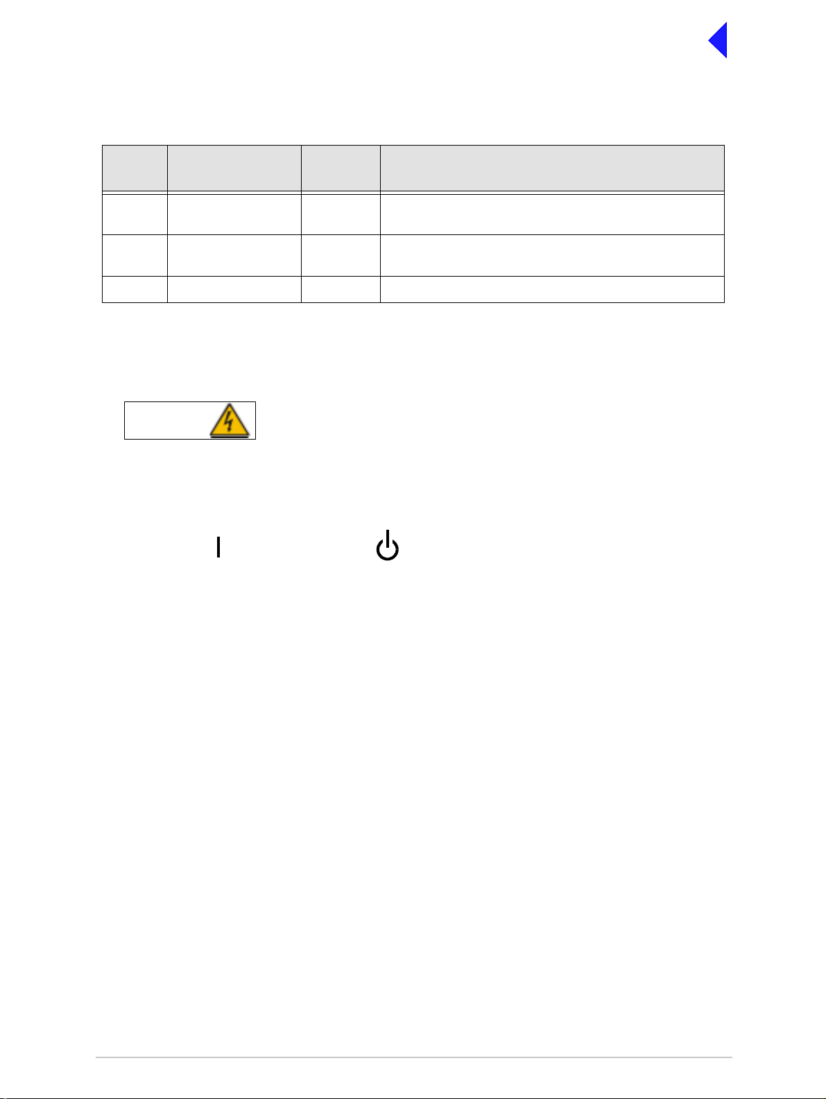
Power Requirements
The transceiver operates from an ac mains supply, or a dc input supply. When both supplies are
connected, the dc input acts as an automatic backup for the ac mains.
ac input supply The transceiver operates from a 48 to 62 Hz single- phase ac supply
and automatically adjusts to operate from any supply voltage ranging
from 110 Vac to 240 Vac ±10%. The power consumption figures are
given in Table 1.
dc input supply The transceiver operates from a dc input supply between 21.6 and
32 V (measured at the radio’s input). The supply current figures are
given in Table 1.
Table 1 Power Consumption
Transmitting or
Receiving
Transmitting Typical 300 VA 8.5 A
Receiving Typical 70 VA 1.2 A
Requirement Normal Operation
ac dc
Maximum 500 VA 12 A
Dimensions and Weight
The dimensions and weight of the transceiver are:
Width 483 mm (19 inches).
Height 88.9 mm (3.5 inches). The height occupies 2U of equipment cabinet
space.
Depth 430 mm (16.9 inches) measured from front panel to rear panel.
Depth 450 mm (17.8 inches) measured from front panel to rear of fan.
Weight 13.5 kg (29.76 pounds).
Environmental
Temperature range The transceiver operates to specification across the temperature
range of -20 to +55°C.
The transceiver can be stored at temperatures ranging from
-30 to +70°C without causing any damage.
Humidity The transceiver operates to specification at a relative humidity
between 5% and 90% non-condensing.
Altitude The radios operate to specification up to 15,000 feet. Additionally the
equipment is capable of storage at altitudes up to 50,000 feet without
damage.
Shock and vibration The radios comply with shock and vibration protection MIL-STD-810E,
method 516.4, procedure VI - Bench Handling. In all cases, no fixed
parts become loose. No movable part or permanently set adjustment
shifts its setting or position.
Page 3
Page 6

Back to Transceiver
Main Page
Ventilation The transceivers are cooled by an integral fan, which normally runs at
half speed. At an RF PA temperature of 45°C this is increased to full
speed and at 40°C it reduces to half speed again.
The transceivers also include an additional temperature controlled fan
contained in the power supply.
Warm up time All variants are fully operational to specification within 20 seconds
after switch on.
Page 4
Page 7

Back to Transceiver
Main Page
AM Modes
Introduction
The transceiver can opera te in AM-V oice m ode and A M-MS K mode. The follow ing spe cificat ion s apply
to both modes unless stated otherwise.
Transceiver Tx RF Characteristics
RF Power Output
The RF carrier ou tput power is adjusta ble in 1 W step s from 5 W to 50 W (as an optio n, the m aximum
selectable power can be limited). Output power is automatically controlled under the following conditions:
Frequency range Variations in power remain within -0 to +1 dB over the operational
frequency range.
Low supply voltage Loop error can reduce power progressively by up to ±1 dB for supply
voltages between 24 Vdc and 32 Vdc.
High VSWR Loop error can reduce power progressively by up to 3 dB. Variations
in power remain within ±1 dB into a VSWR of up to 2.5:1 At VSWRs
greater than this the output power may be reduced by 10 dB ±1 dB.
High RF PA temperature If the RF PA temperature sensor exceeds 80° C the output power is
reduced by 3 dB ±1 dB. If the RF PA temperature sensor exceeds
90°C the transceiver is de-keyed and automatically re-keyed at 70°C.
Duty Cycle
100% continuous operation.
Channel Spacing
AM-Voice The transceivers are capable of both 25 kHz channel spacing and
8.33 kHz channel spacing.
AM-MSK 25 kHz only.
Offset Carrier
AM-Voice The T6TR is capable of offsetting the carrier frequency to provide 2, 3
and 4 carrier offset.
AM-MSK Not available
Harmonic Outputs
Second harmonic outputs are less than -36 dBm, third harmonic
outputs are less than -46 dBm and fourth harmonic outputs and above
up to 4 GHz are less than -56 dBm.
Spurious Outputs
The spurious outputs are less than -46 dBm for modulation depths up
to 90%, measured at greater than 500 kHz from carrier in the
frequency range 9 kHz to 4 GHz. There are no coherent spurious
outputs above the spectral mask at less than 500 kHz.
Page 5
Page 8

Back to Transceiver
Main Page
Intermodulation
Intermodulation products, caused by an interfering signal with the
same power as the transmitter isolated by 30 dB, are at least -40 dBc
at ≥±150 kHz and -50 dBc at ≥±500 kHz.
Transceiver Rx RF Characteristics
Sensitivity
118 to 136.975 MHz 12 dB SINAD for -107 dBm 30% modulated.
112 to 117.975 MHz 12 dB SINAD for -105 dBm 30% modulated
and
137 to 155.975 MHz
Notes ...
(1) All references to SINAD in this document include ITU-T recommendation P.53 weighting.
(2) When operating the transce iver in combined T/R antenna con figuration, the sensitivity figures
are degraded by 1 dB.
Channel spacing
AM-Voice mode 25 kHz, or 8.33 kHz.
AM-MSK mode 25 kHz.
IF selectivity
For 25 kHz channel spacing At ±11 kHz from the centre frequency, the signal is attenuated by less
than 6 dB.
At ±25 kHz from the centre frequency, the signal is attenuated by more
than 80 dB.
For 8.33 kHz channel spacing At ±3.5 kHz from the centre frequency, the signal is attenuated by less
than 6 dB.
At ±8.33 kHz from the centre frequency, the signal is attenuated by
more than 70 dB (60 dB using the ETSI test method).
At ±25 kHz from the centre frequency, the signal is attenuated by more
than 80 dB.
Unwanted Signal Suppression
Intermod signal suppression The intermodulation signal suppression is 80 dB or greater (reference
12 dB SINAD) for two unwanted signals spaced 100 kHz
(unmodulated) and 200 kHz (30% modulation) from the channel
frequency.
Blocking ratio 95 dB or greater (reference 12 dB SINAD and degraded by 6 dB) in
the presence of an unmodulated unwanted signal spaced at 200 kHz
from the channel frequency.
105 dB or greater (reference 12 dB SINAD and degraded by 6 dB) in
the presence of an unmodulated unwanted signal spaced at 3 MHz
from the channel frequency.
Page 6
Page 9

Back to Transceiver
Main Page
Cross-modulation rejection 95 dB or greater (reference 30 dB SINAD and degraded by 10 dB) in
the presence of a 30% modul ated unwant ed signal spac ed at 200 kHz
from the channel frequency.
105 dB or greater (reference 30 dB SINAD and degraded by 10 dB) in
the presence of a 30% modulated unwanted signal spaced at 3 MHz.
Spurious signal suppression 90 dB, or greater (reference 12 dB SINAD) for a 30% modulated
unwanted signal spaced by more than two channels from the tune
frequency up to 1 GHz, 80 dB or greater for frequencies up to 2 GHz
and 70 dB or greater for frequencies above 2 GHz..
Interfering signals At least 6 dB SINAD is achieved for a wanted -87 dBm signal
modulated with a 1 kHz tone 30% in the presence of two -5 dBm
interfering signals, both FM modulated, one with a 19 kHz tone
7.5 kHz deviation at 107.9 MHz and varied by ±4 kHz the other with a
19.1 kHz tone 7.5 kHz deviation with its frequency chosen such that
one of the 3
rd
order products is located on the chosen receive
frequency.
Antenna radiation
Radiation at the antenna socket is less than -81 dBm, typically less
than -100 dBm, within the frequency range 9 kHz to 4 GHz.
Maximum RF Input
The transceiver can withstand an RF input of +36 dBm for 20 seconds,
and a continuous +27 dBM input, without causing damage.
Transceiver Tx Modulation Characteristics
The transceiver Tx modulation characteristics are as follows:
Mode
AM-Voice mode The AM-Voice mode uses Double Side Band (DSB) Amplitude
Modulation (AM) full carrier, emission designator 6K80A3EJN for
25 kHz channels and 5K00A3EJN for 8.33 kHz channels.
AM-MSK The AM MSK mode uses Double Side Band (DSB) Amplitude
Modulation (AM) full carrier, emission designator 13K0A2DJN.
Modulation Depth
The transceiver is capable of modulation depths up to 95%.
Hum and Noise
The hum and noise is more than 45 dB below the signal level for line
input levels <-13 dBm, and more than 50 dB below the signal level for
line input levels ≥−13 dBm, for a carrier modulated by a 1 kHz signal
with a modulation depth of 90%.
Page 7
Page 10

Back to Transceiver
Main Page
Frequency Response
25 kHz channel spacing The variation in frequency response with reference to a 1 kHz signal
is within +0.5 dB and -1.5 dB across the frequency range 300 to
3400 Hz. The response is also less than -20 dB at 100 Hz and below,
and less than -30 dB at 4 kHz and above.
8.33 kHz channel spacing The variation in frequency response with reference to a 1k Hz signal
is within +0.5 dB and -1.5 dB across the frequency range 350 Hz to
2500 Hz. The response is also less than -10 dB at 100 Hz and below,
and less than -30 dB at 3200 Hz and above.
Distortion
25 kHz channel spacing The total harmonic distortion is less than 5% due to signals with a
modulation depth of 90%, within the frequency range 300 Hz to
3400 Hz.
8.33 kHz channel spacing The total harmonic distortion is less than 5% due to signals with a
modulation depth of 90%, within the frequency range 350 Hz to
2500 Hz.
Residual FM
For a test signal of 1 kHz set at 80% modulation depth applied to the
line input of the transceiver, the unwanted peak frequency modulation
does not exceed ±500 Hz.
VOGAD
AM-Voice The VOGAD has an operational range of 30 dB. The VOGAD can be
disabled.
AM-MSK VOGAD permanently disabled.
Mute
AM-Voice The mute level is set at 15 dB below the average speech line level
setting. The mute can be disabled.
AM-MSK The mute is permanently disabled.
Differential group delay
AM-MSK only There is a 60 µs of differential group delay for signals in the range
1200 to 2400 Hz.
Transceiver Rx Modulation Characteristics
The transceiver Rx modulation characteristics are as follows:
Mode
AM-Voice mode The AM-Voice mode uses Double Side Band (DSB) Amplitude
Modulation (AM) full carrier, emission designator 6K80A3EJN for
25 kHz channels and 5K00A3EJN for 8.33 kHz channels.
AM-MSK The AM-MSK mode uses Double Side Band (DSB) Amplitude
Modulation (AM) full carrier, emission designator 13K0A2DJN.
Page 8
Page 11

Back to Transceiver
Main Page
Frequency response
25 kHz channel spacing The variation in frequency response with reference to a 1 kHz signal,
is within +1 dB and -2 dB across the frequency range 300 to 3400 Hz.
The response is less than -20 dB for frequencies at or below 100 Hz,
and less than -30 dB at 4 kHz and above.
8.33 kHz channel spacing The variation in frequency response with reference to a 1 kHz signal,
is within +1 dB and -2 dB across the frequency range 350 to 2500 Hz.
The response is less than -10 dB for frequencies at or below 100 Hz,
and less than -30 dB at 4 kHz and above.
Distortion
25 kHz channel spacing For RF input signals between -53 dBm and +10 dBm, the total
harmonic distortion is less than 5% within the frequency range 300 Hz
to 3.4 kHz when the modulation depth is between 30 and 90%.
8.33 kHz channel spacing For RF input signals between -53 dBm and +10 dBm, the total
harmonic distortion is less than 5% within the frequency range 350 Hz
to 2.5 kHz when the modulation depth is between 30 and 90%.
Wanted Signal Dynamic Range (RF AGC)
For a 90% modulated on-channel signal, a change in signal level from
-107 dBm to +10 dBm results in less than a 3 dB change in audio
output. On-channel signals modulated at 90% up to a level of
+17 dBm achieve at least 10 dB SINAD.
Audio AGC
AM-Voice Mode The audio AGC compresses a 30% to 90% variation in input
modulation depth to an audio output power change of 1 dB or less.
The audio output level is maintained at the equivalent of 90%
modulation. Audio AGC can be disabled.
AM-MSK Mode The audio AGC is permanently disabled.
Squelch
The transceiver has a noise compensated carrier operated squelch
with an adjustment range of -114 to -60 dBm, and providing greater
than 60 dB of quieting. Note that when the RF pre-attenuator is
switched in, the adjustment levels are increased by 6 dB.
The squelch has a noise compensation disable facility to provide
carrier only operation.
Transceiver Tx Control
Transceiver Tx control characteristics are as follows:
Audio Inputs
AM-MSK AM-MSK data is connected to the transceiver via an external modem
connected to the line inputs.
Page 9
Page 12

Back to Transceiver
Main Page
AM-Voice Voice can be connected to the transceiver via the front panel
microphone connector. Voice can also be connected via the line
inputs. Line level setting from -30 to +10 dBm.
PTT Time-Out
The time-out period is adjustable from 2 to 510 seconds in 2 second
steps or can be disabled.
Tranceiver Rx Control
AM-Voice Audio Outputs
The transceiver’s outputs are the remote audio line output, the headset
output and the loudspeaker. Line level output is adjustable between -30
and +10 dBm.
AM-MSK Output
AM-MSK data is connected to an external modem through the remote
audio line output.
Page 10
Page 13

Back to Transceiver
Main Page
Mode 2
Introduction
This section gives the transceiver’s specification applicable to Mode 2 operation. Mode 2 parameters are
identical to AM-Voice mode with the following exceptions:
Transceiver Tx RF Characteristics
RF Power Rise Time
The transceiver produces more than 90% of full power output within
the first 2 symbols of the power stabilization segment, which is the first
segment of the training sequence and consists of 4 symbols each
representing 000.
RF Power Decay Time
The output power decays by more than 20 dB within 2.5 symbo ls of
the middle of the final symbol.
Channel Spacing
25 kHz channel spacing only.
Transceiver Tx Modulation Characteristics
Mode
Mode 2 uses Carrier Sense Multiple Access (CSMA) differentially
encoded 8-phase shift keying (D8PSK), using a raised cosine filter
with α =0.6 (nominal value), emission designator 14K0G1DE.
Information is differentially encoded with 3 bits per symbol transmitted
as changes in phase rather than absolute phase. The data stream is
divided into groups of 3 consecutive data bits, least significant bit first.
Zeros are padded to the end of transmissions if needed for the final
channel symbol.
Modulation Rate
The symbol rate is 10,500 symbols/second (±0.005%), resulting in a
nominal bit rate of 31,500 bits/s.
RMS Phase Error
The RMS phase error is less than 3°. The error vector magnitude is
less than 6%.
Phase Acceleration
The total frequency change during the transmission of the unique word
is less than 10Hz. After this, the phase acceleration is less than
500 Hz/s.
Page 11
Page 14

Transceiver Rx RF Characteristics
Sensitivity
The transceiver has a sensitivity better than -102dBm for 1x10
Decoding off.
Channel Spacing
Mode 2 channel spacing is 25 kHz.
IF Selectivity
At ±11 kHz from the centre frequency, the signal is attenuated by less
than 6 dB.
At ±25 kHz from the centre frequency the signal is rejected by more
than 80 dB.
Back to Transceiver
Main Page
-3
Bit Error Rate (BER) with Reed Solomon
Unwanted Signal Suppression
With the required signal at -92 dBm, a BER of better than 1x10
Reed Solomon Decoding switched off is achieved under the following
conditions:
❑ An interfering signal at -32 dBm on an adjacent channel
❑ One or more out-of- band i nterfer ing s ignals h aving a tota l lev el of
-33 dBm
❑ One or more VHF FM broadcast signals having a total level of
-5 dBm
❑ Co-channel rejection better than 20 dB.
Synchronisation
For received signals greater than -103 dBm, the probability of
synchronisation is greater than 0.999. The pr obability of false
synchronisation is 3x10
Transceiver Rx Modulation Characteristics
Mode 2 uses Carrier Sense Multiple Access (CSMA) differentially
encoded 8-phase shift keying (D8PSK) using a raised cosine filter with
α = 0.6 (nominal value), emission designator 14K0G1DE.
-3
with
-3
Wanted Signal Dynamic Range (RF AGC)
A BER better than 1x10
achieved for received signals of -102 dBm to +10 dBm.
Frequency Offsets
The transceiver operates with frequency offsets up to 826 Hz.
Page 12
-3
with Reed Solomon Decoding off is
Page 15

Back to Transceiver
Main Page
Mode 3
Introduction
This section gives the transceiver’s specification applicable to Mode 3 operation. Mode 3 parameters are
identical to AM-Voice mode with the following exceptions:
Transceiver Tx RF Characteristics
RF Power Rise Time
The transceiver produces more than 90% of full power output within
the first 2 symbols of the power stabilization segment, which is the first
segment of the training sequence and consists of 4 symbols each
representing 000.
RF Power Decay Time
The output power decays by more than 20 dB within 2.5 symbo ls of
the middle of the final symbol.
Channel Spacing
25 kHz channel spacing only.
Transceiver Tx Modulation Characteristics
Mode
Mode 3 uses Time Division Multiple Access (TDMA) differentially
encoded 8-phase shift keying (D8PSK), using a raised cosine filter
with α=0.6 (nominal value), emission designator 14K0G7WET.
Information is differentially encoded with 3 bits per symbol transmitted
as changes in phase rather than absolute phase. The data stream is
divided into groups of 3 consecutive data bits, least significant bit first.
Zeros are padded to the end of transmissions if needed for the final
channel symbol.
Modulation Rate
The symbol rate is 10,500 symbols/second (±0.005%), resulting in a
nominal bit rate of 31,500 bits/s.
RMS Phase Error
The RMS phase error is less than 3°. The error vector magnitude is
less than 6%.
Phase Acceleration
The total frequency change during the transmission of the unique word
is less than 10Hz. After this, the phase acceleration is less than
500 Hz/s.
Page 13
Page 16

Transceiver Rx RF Characteristics
Back to Transceiver
Main Page
Sensitivity
Channel Spacing
IF Selectivity
Unwanted Signal Suppression
The transceiver has a sensitivity better than -102dBm for 1x10
-3
Bit
Error Rate (BER) with Reed Solomon Decoding off.
In order to improve co-location performance where maximum
sensitivity cannot be realized due to large unwanted signals, the
transceiver’s sensitivity can be reduced by 6 dB. This is achieved by
switching on the 6 dB RF pre-attenuator from the front panel menu
system.
Mode 3 channel spacing is 25 kHz.
At ±11 kHz from the centre frequency, the signal is attenuated by less
than 6 dB.
At ±25 kHz from the centre frequency the signal is rejected by more
than 80 dB.
With the required signal at -92 dBm, a BER of better than 1x10
-3
with
Reed Solomon Decoding switched off is achieved under the following
conditions:
❑ An interfering signal at -32 dBm on an adjacent channel
❑ One or more out-of- band i nterfer ing s ignals h aving a tota l lev el of
-33 dBm
❑ One or more VHF FM broadcast signals having a total level of
-5 dBm
❑ Co-channel rejection better than 20 dB.
Synchronisation
For received signals greater than -103 dBm, the probability of
synchronisation is greater than 0.999. The pr obability of false
synchronisation is 3x10
Transceiver Rx Modulation Characteristics
Mode 3 uses Time Division Multiple Access (TDMA) differentially
encoded 8-phase shift keying (D8PSK) using a raised cosine filter with
α = 0.6 (nominal value), emission designator 14K0G7WET.
Wanted Signal Dynamic Range (RF AGC)
A BER better than 1x10
for received signals of -102 dBm to +10 dBm. The AGC attack time is
less than 0.5 ms and the decay time is less than 1 ms for a 40 dB step
input.
-3
.
-3
with Reed Solomon decoding off is achieved
Frequency Offsets
The transceiver operates with frequency offsets up to 826 Hz.
Page 14
Page 17

Operation
Back to Transceiver
Main Page
This document describes the controls, indicators, setting up and operating instructions
applicable to the T6TR VHF Multimode Transceiver.
Part 1 Controls and Indicators
Part 2 Setting Up and Operation
Page 1
Page 18

Back to Transceiver
Main Page
Controls and Indicators
This part details the purpose of all controls and indicators of the T6TR transceivers.
Front Panel
The front panel’s controls, indicators and connectors are shown below and detailed in the following
paragraphs.
Scroll SwitchLCD
ALARM
RECEIVE
TRANSMIT
READY
STANDBY
F r e q 1 1 8 .0 0 0 M H z
C h 1 0 0 + 7 . 3 k H z
M o d e A M V o i c e 1
P w r
SCROLL/
SELECT
REFERENCE
HEADSET/
MICROPHONE/
DIAGNOSTICS
Scroll/Select Switch and LCD
The Scroll/Select switch is used in conjunction with the LCD to select most of the transceiver's
operational settings. Use of the switch and LCD is fully detailed in the section of this user guide applicable
to the particular operatin g mod e. Dur i ng norm al op er ati on, th e LCD sh ows the op erati ng fr equ ency , the
channel number (if the channel store facility is used), the carrier offset (if used), and displays a graphical
representation of instantaneous peak power.
The example LCD scree n below shows the tr ansceiver operat ing on 118.000 M Hz; the frequency has
been preset as channel 100 and offset at +7.3 kHz.
Transmit Indicator
An amber indicator that lights when the transmit circuit is keyed and producing output power.
Receive Indicator
An amber indicator that lights when a signal is received that is above the squelch threshold. Additionally,
this indicator is lit when the transceiver's squelch facility is switched off (squelch defeated). This indicator
also lights when the transceiver is keyed.
Alarm Indicator
A red indicator that either flashes, or lights, when a BIT fault has been de tected. BIT indications are
classified as either Alarms or Alerts.
If an ‘alert’ conditi on is detected, the Alarm i ndicator flashes, the Ready i ndicator remains lit, and the
transceiver remains operational. A BIT ‘alert’ is indicated if:
❑ If the transceiver RF output power has red uced from its setting by more than 1 dB b ut not more
than 3 dB
❑ If the supply volts falls below a pre-defined level.
Any other BIT condit ion results in an alarm. When detected, the Alarm indicator lights and the Ready
indicator becomes unlit; the transceiver cannot be used.
Page 2
Page 19

Back to Transceiver
Main Page
Ready Indicator
A green indicator that lights when the transceiver is ready for use and no BIT faults have been detected.
Standby Indicator
A red indicator that ligh ts wh en the transceiver is in stan dby mo de. W hen in standby mode, most of the
radio's circuits are inactive, the front panel LCD is blanked, and the transceiver cannot be keyed.
Standby mode is selected and deselected using the front panel Scroll/Select switch and LCD, by initiating
an instruction th rough a MARC system, th rough a T6 control ler or through the V FP. For d etails of front
panel selection and deselection see page 15.
Reference Connector
An SMB jack soc ket that allows a frequency coun ter to monitor the tr ansceiver's re ference frequen cy.
This connector is used onl y for mainte nance pur poses. The in structions for checki ng and adjus ting the
reference frequency are given in the Maintenance section.
Headset/Microphone/Diagnostics Connector
A dual purpose connector that allows either a headset/microphone, or a PC, to be connected to t he
transceiver. The connector is a 7-pin self-locking DIN socket; the pin-out is shown in Table 1.
A microphone is fitted to this con nec tor to e nabl e th e tr ansce iv er to be operat ed i n AM loc al mode . T he
connections are detailed in Table 1. A PC can also be connected to allow the VFP to be displayed. Using
the VFP is detailed in the T6TR maintenance section. The PC connections at the transceiver are shown
in Table 2 on page 4.
Viewed from front
Table 1 Headset/Microphone/Diagnostics Connector - Audio Connections
Pin
Number
1 Microphone ground - 0 V.
3 Microphone PTT Input 0 V to PTT.
Signal
Input or
Output
Description
5 Sidetone/headset drive Output 0 to 3 V pk-pk.
6 Microphone input Input 2 to 35 mV rms on Passive setting and 8 to 140 mV rms
on Active setting to remain in VOGAD range.
7Ground - 0V.
Page 3
Page 20
Back to Transceiver
Main Page
Table 2 Headset/Microphone/Diagnostics Connector - PC Connections
Pin
Number
2 Transmit data Output RS232, 115200 baud, 8 data bits, 1 stop bit, no parity, no
4 Receive data Input RS232, 115200 baud, 8 data bits, 1 stop bit, no parity, no
7 Ground - 0 V.
Signal
Input or
Output
Description
handshaking.
handshaking.
Rear Panel Power Switch
The rear panel's power switch is a 2-way rocker switch used to select between power on, and standby.
WARNING
When the Power Switch is set to the Standby position, dangerous voltages are s till prese nt
in the transceiver's internal power supply circuitry. To ensure safe working, the transceiver
must be isolated from the ac and dc input supplies.
Dangerous Voltages
= Standby= On
Page 4
Page 21

Back to Transceiver
Main Page
Setting Up and Operation
Introduction
Setting up the transcei ver involves selecting vari ous parameters using the Virt ual Front Panel (VFP),
through a Multi-Acces s Remote Control (M ARC) system , from a T6 co ntrol ler, or from the transc eiver’ s
front panel. The transceiver can be configured for remote or local use.
Table 11 on page 35 details the functions and parameters that can be set from all these sources.
The rest of this doc ument details how to configure the transce iver from the front panel, and how to
operate the radio in local mode.
Selecting most of th e transce iver' s operati onal set tings is carri ed out usin g the front panel Scro ll/Se lect
switch and the LCD (see the illustration below). No attempt to set up the transceiver should be made until
the transceiver has been installed as per the installation procedures given in the Installation section.
Normal Operation
During normal operation, the LCD displays the Main screen. This screen shows the operating frequency,
the channel number (i f the channel store facility is used), the c arrier offset (if used), and displays a
graphical representa tion of outp ut powe r when the trans ceive r is keyed . If the trans ceiv er has been set
to Standby mode, which is shown by the front panel Standby Indicator being lit, the LCD is blanked.
Scroll SwitchLCD
RECEIVE
ALARM
TRANSMIT
READY
STANDBY
F r e q 1 1 8 .0 0 0 M H z
C h 1 0 0 + 7 . 3 k H z
M o d e A M V o i c e 1
P w r
SCROLL/
SELECT
REFERENCE
HEADSET/
MICROPHONE/
DIAGNOSTICS
Using the Scroll/Select Switch
The Scroll/Select switc h (referred to throughout this section as the ‘Switch’) is used to leav e the Main
screen and display the Control screen (see page 8). Further use of the Switc h di splays vari ous sel ectio n
menus and allows t he required parameters to be set. Th e switch has three actions: it can b e turned
clockwise, anti-clockwise, or momentarily pushed in.
Page 5
Page 22

Back to Transceiver
Main Page
Screen Protocol
The following protocol is applicable to all screens described in this document.
Main Screen During normal transceiver operation, the Main screen, an example of which is shown
below, is disp layed.
F r e q 1 1 8 . 0 0 0 M H z
C h 1 0 0 + 7 . 3 k H z
M o d e A M V o i c e
V o l I I I I I I I I I I
Switch Refers to the front panel Scroll/Select switch. The switch is turned clockwise to scroll
through fields from left to right, and from top to bottom. The switch is turned
anti-clockwise to scroll through fields from right to left, and from bottom to top. The
switch is pressed to make a selection.
Time out If during any setting up procedure the Scroll/Select switch is not operated for
30 seconds, the display returns to the Main screen. If editing any parameter has not
been completed, the transceiver stays on the original setting.
>> Indicates more fields are available other than those currently displayed. To access
those fields, turn the switch clockwise through the last displayed field.
<< Indicates more fields are available other than those currently displayed. To access
those fields, turn the switch anti-clockwise through the first displayed field.
Back When Back is selected, you are returned to the previous menu.
Exit When Exit is selected, you are returned to the Main screen.
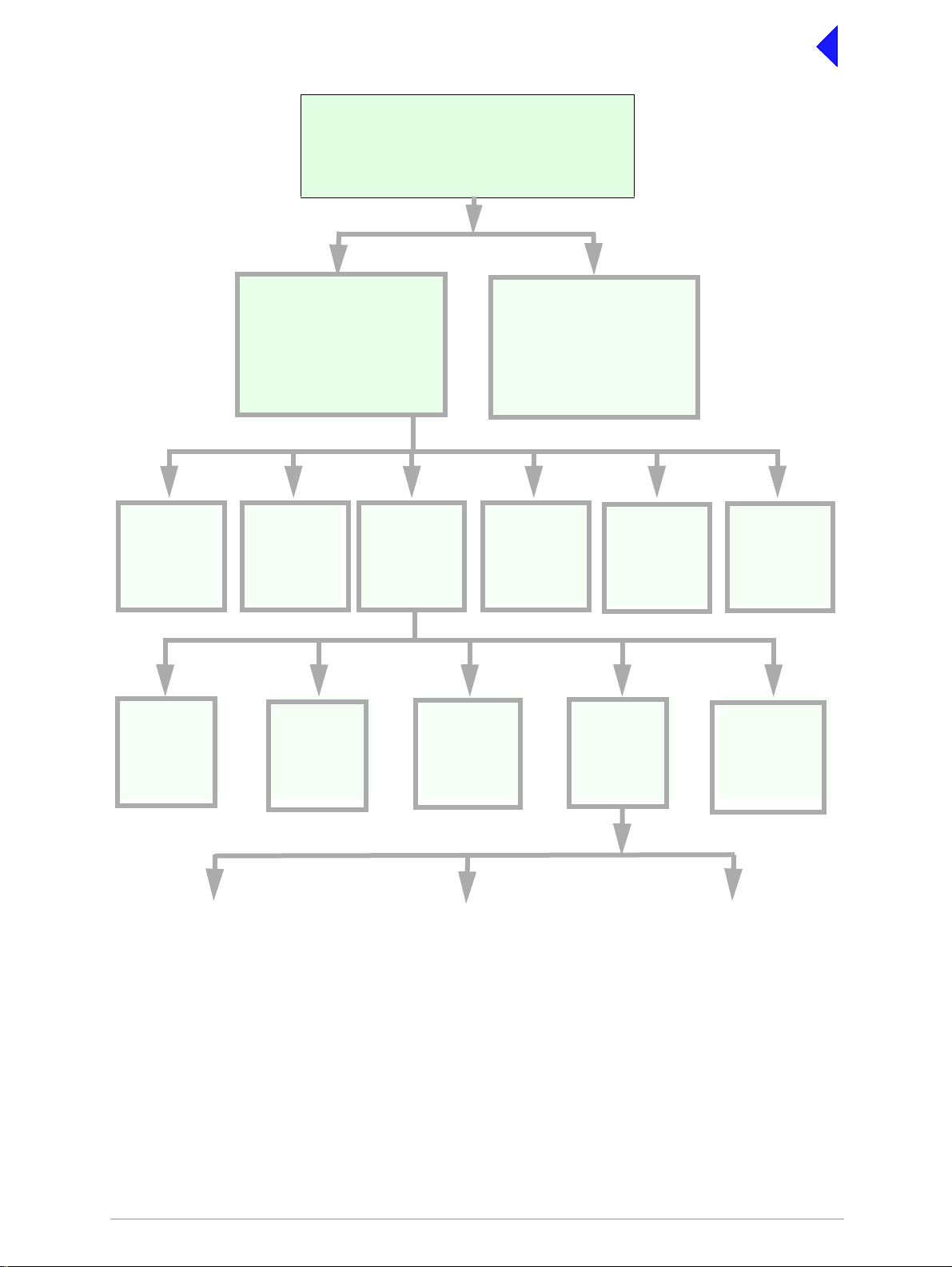
Menu System
The front panel control of the radio is implemented through a hierarchical menu system as shown on the
following page.
Page 6
Page 23
Back to Transceiver
Main Page
F r e q 1 1 8 . 0 0 0 M H z
C h 1 0 0
M o d e A M V o i c e
V o l I I I I I I I I I I
Main Screen
Displayed during normal
transceiver operation
with the transceiver
unkeyed.
Frequency
Set the
transceiver’s
operating
frequency
Backlight
Adjust the
display’s
backlight
Control Screen
Configure the transceiver’s
operating parameters, ac cess
the BIT facility or view the
software configuration.
Channel
Set or recall up
to 100 preset
frequency
channels
Settings
Set the
transceiver’s
operational
settings
Ref Freq
Adjust the
transceiver’s
reference
frequency
Initiate a BIT
test and view
Band Edges
Set up the
transceiver’s
band edges
Menu Lock Screen
(see page 8)
BIT
results
S/W Config
transceiver’s
configuration
Mode and
Mode
Settings
Select Mode
View the
software
Standby
Enter or Exit
standby mode
Polarities
Set the active
polarity for
certain hardwire
connections
AM-Voice Mode
Settings
(see page 19)
AM-MSK Mode
Settings
(see page 20)
Menu System
Page 7
Digital Modes
(see page 23)
Page 24

Back to Transceiver
Main Page
Menu Lock Screen
A security facility available onl y from the VFP allows the trans ceiver's f ront panel to be ‘l ocked’. Wh en
this facility is active, no operational settings can be made from the front panel until an ‘unlock’ command
is sent from the VFP.
The following screen is displayed when ‘lock’ is active, and the front panel switch is pressed.
S E C U R I T Y M E S S A G E
F r o n t P a n e l
L o c k e d
O K
To exit the system lock screen:
❑ Select OK, then press the switch. You are returned to the Main screen.
or,
❑ Wait for the 30 second time-out to expire. You are returned to the Main screen.
Control Screen
The Control screen is entered from the Main screen by pressin g the switch. The following screen is
displayed:
Change the transceiver’s operating frequency.
Store or recall preset channel frequencies.
Select operating mode and mode settings.
Initiate a BIT test and view results.
View software configuration.
Enter or exit standby mode.
F r e q u e n c y
C h a n n e l
S e t t i n g s
E x i t > >
B I T
S / W C o n f i g
S t a n d b y
E x i t < <
Page 8
Page 25

Back to Transceiver
Main Page
Notes for Setting Up the Transceiver
The following notes should be read before setting up the transceiver. They advise on the special
frequency displa y when using 8.33 kHz chan nel spacin g, and give guidan ce on the o ptimum line l evel
settings. Note that for operation in the United States of America, this equipment is certified only for
operation using 25 kHz channel spacing.
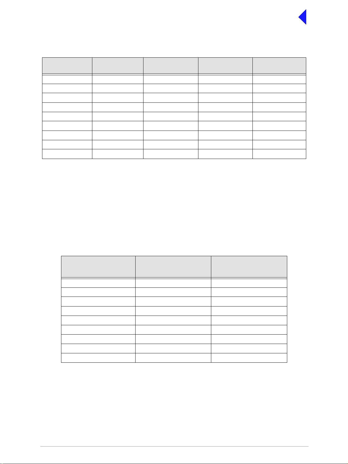
Front Panel Display for 25 kHz and 8.33 kHz Channel Spacing
When setting the oper ating frequ ency of the tra nsce iver an d 8.33 kH z ch annel sp acing is s elected, the
displayed frequency differs from the actual channel frequency. Table 3 shows the pattern used for
25 kHz and 8.33 kHz spaced channel frequencies from 118.000 MHz to 118.141 MHz. The pattern is the
same for any frequency within the transceiver's frequency range. The display conforms to ICAO
convention for 8.33 kHz operation.
Table 3 25 kHz and 8.33 kHz Channel Spacing Displays
Actual Frequency
(to 4 decimal places)
118.0000 MHz
118.0000 MHz
118.0083 MHz
118.0166 MHz
118.0250 MHz
118.0250 MHz
118.0333 MHz
118.0416 MHz
118.0500 MHz
118.0500 MHz
118.0583 MHz
118.0666 MHz
118.0750 MHz
118.0750 MHz
118.0833 MHz
118.0916 MHz
118.1000 MHz
118.1000 MHz
118.1083 MHz
118.1166 MHz
Channel
Spacing
25 kHz
8.33 kHz
8.33 kHz
8.33 kHz
25 kHz
8.33 kHz
8.33 kHz
8.33 kHz
25 kHz
8.33 kHz
8.33 kHz
8.33 kHz
25 kHz
8.33 kHz
8.33 kHz
8.33 kHz
25 kHz
8.33 kHz
8.33 kHz
8.33 kHz
Displayed Frequency
at Transceiver's Front Panel
118.000 MHz
118.005 MHz
118.010 MHz
118.015 MHz
118.025 MHz
118.030 MHz
118.035 MHz
118.040 MHz
118.050 MHz
118.055 MHz
118.060 MHz
118.065 MHz
118.075 MHz
118.080 MHz
118.085 MHz
118.090 MHz
118.100 MHz
118.105 MHz
118.110 MHz
118.115 MHz
118.1250 MHz
118.1250 MHz
118.1333 MHz
118.1416 MHz
25 kHz
8.33 kHz
8.33 kHz
8.33 kHz
118.125 MHz
118.130 MHz
118.135 MHz
118.140 MHz
Input Line Level Settings
The input line lev el setting displayed on the f ro nt pa nel is eq uiv al en t to the average speech le vel wi th a
peak-to-average ratio of 13 dB. This corresponds to the level specified for the lines.
When testing the transceiver using a sine wave, the line input level should be set to 10 dB above the line
level setting. The VOGAD and mute thresholds are p re-set at 10 dB and 15 dB respectively below the
line level setting.
Table 4 shows the relationship between the input line level, VOGAD threshold and mute threshold.
Page 9
Page 26
Back to Transceiver
Main Page
Table 4 Relationship Between Line Level, VOGAD Threshold and Mute Threshold
Line Level
Setting (dBm)
+10 +10 +20 0 -5
+5 +5 +15 -5 -10
00+10-10-15
-5 -5 +5 -15 -20
-10 -10 0 -20 -25
-15 -15 -5 -25 -30
-20 -20 -10 -30 -35
-25 -25 -15 -35 -40
-30 -30 -20 -40 -45
Average Speech
Level (dBm)
Sine Wave Level
(dBm)
VOGAD Threshold
(dBm)
Mute Threshold
(dBm)
Output Line Level Setting
The output line level setting displayed on the front panel is equivalent to the average speech level with a
peak-to-average ratio of 13 dB. This corresponds to the level specified for the lines.
When testing the transc eiver using a signal gen erator with sine wave mo dulation, the line output le vel
will be 10 dB above the line level setting.
Table 5 shows t he relationship between line level, output levels with av erage speech and sine wave
(assuming that the audio AGC is set to on, and the modulation depth is between 30% and 100%).
Table 5 Relationship between Line Level, Output Levels with Average Speech
and Sine Wave
Line Level Setting
(Front Panel Setting)
(dBm)
+10 +10 +20
+5 +5 +15
00+10
-5 -5 +5
-10 -10 0
-15 -15 -5
-20 -20 -10
-25 -25 -15
-30 -30 -20
Output Level with
Average Speech
(dBm)
Output Level with
Sine Wave
(dBm)
Page 10
Page 27

Back to Transceiver
Main Page
Changing the Transceiver’s Operating Frequency
The transceiver’s frequency can be changed in two ways: either from the frequency screen, or by
recalling a preset channel. This procedure details using the Frequency screen.
(1) From the Control screen, select
frequency to display the Frequency
screen.
(2) Turn the switch to highlight the dig it to
be changed, then press the switch.
(3) Turn the switch until the required digit
is shown, then press the switch.
(4) Repeat until the required frequ ency is
shown, then highlight OK and press the
switch.
F r e q 1 1 8 . 0 0 0 M H z
C a n c e l O K
Page 11
Page 28

To Store and Recall Frequency Channels
Up to 100 frequency channels can be stored in the transceiver.
To store a Channel Frequency
(1) From the Control screen, select
Channel to display the Channel
screen. Highlight Channel, press the
switch and then turn it until the required
channel number is displayed; press the
switch.
(2) Highlight the MHz frequency value
(see Example 2), press the s wit ch and
then turn it until the required MHz value
is shown. Press the switch.
(3) Highlight the kHz frequency value (see
Example 3), press the swi tch and the n
turn it until the required kHz value is
shown. Press the switch.
(4) Highlight Store and press the switch.
The new frequency is now stored in the
selected channel number.
To recall a Stored Frequency Channel
(1) From the Control screen, select
Channel to display the Channel
screen.
(2) To make the transceiver operate on any
preset channel frequency, highlight
Channel and press the switch. Turn the
switch until the required channel
number/frequency is displayed, then
press the switch.
(3) Turn the switch to highlight Recall, then
press the switch. E xit the screen. The
transceiver now operates on the
recalled channel frequency.
C h 1 0 0
F r e q 1 2 1 . 5 0 0 M H z
R e c a l l
B a c k E x i t
Channel Screen - Example 1
C h 1 0 0
F r e q 1 1 8 . 0 0 0 M H z
S t o r e
B a c k E x i t
Channel Screen - Example 2
C h 1 0 0
F r e q 1 1 8 . 0 0 0 M H z
O u t s i d e B a n d E d g e
B a c k E x i t
Channel Screen - Example 3
C h 1 0 0
F r e q 1 1 8 . 0 0 0 M H z
I nn v a l i d f o r M o d e
B a c k E x i t
Channel Screen - Example 4
Back to Transceiver
Main Page
Notes:
If a frequency ou tside the band edge limits is
entered, a message (see Channel Screen Example 3) is displayed.
If a frequency not valid for the mode of
operation is entere d, a m es sage ( se e Cha nne l
Screen - Example 4) is displayed.
Page 12
Page 29

Back to Transceiver
Main Page
To Initiate a BIT Test
Use the following procedur e to initiate an interrup tive BIT test from the transceiver's fro nt panel. A BIT
test cannot be initiat ed while the transceiv er is keyed . After a BIT test has been run, the BIT scre en is
displayed (see AM-Voice and AM-M SK BIT Screen on page 28). An interruptive BIT test cannot be
initiated in Mode 2 or Mode 3.
During an interruptive BIT test, the transceive r radiates modu lated carr ier waves at the set
power. Users should therefore obtain the necessary authority before initiating a test.
If the test is to be carri ed out with the antenna discon nected, ensure a l oad is fitted to t he
transceiver's antenna connector.
In order to test the line input stages, an internally generated 1 kHz tone is injected into the
line input circuit. Any other audio present on the line input will cause the test to be
inaccurate. Therefore the transceiver must not be keyed during the test.
(1) From the Main scr een, pres s the s witch to d isplay the Contr ol scr een. Tu rn the s witch unt il BIT
is highlighted. Press the switch.
B I T
S / W C o n f i g
S t a n d b y
E x i t < <
(2) Ensure the BIT menu is displayed. Turn the switch until BIT Initiate is highlighted. Press the
switch.
B I T I n i t i a t e
E T I 0 0 0 0 0 : 0 0 h r s
A C S u p p l y O N
E x i t > >
(3) During the test, which takes approximately two seconds, the Testing screen is displayed.
T e s t i n g
P l e a s e W a i t
(4) On completion, and if the interruptive test was initiated from the front panel, one of the following
screens will be shown.
Page 13
Page 30

Back to Transceiver
Main Page
T e s t S t a t u s
P A S S
O K
(5) Selecting OK takes the user back to the BIT screen.
T e s t S t a t u s
F A I L
O K
(6) Selecting OK takes the user back to the BIT screen. The user can then scroll through the screen
to check out transceiver parameters for failure.
Page 14
Page 31

Back to Transceiver
Main Page
Standby Mode
Standby mode is a power saving feature that can be used for non-ope rational transceivers. Whe n in
standby mode, most of t he transceiver's cir cuits are inactive, t he LCD is blanked, an d the transceiver
cannot be keyed. To put the transceiver into standby mode, use the following procedure.
When the transceiver is in Standby mode, the red front panel Standby indicator is lit.
To Enter Standby Mode
(1) From the Control screen select
Standby.
(2) At the Standby screen, select Yes.
E n t e r S t a n d b y ?
(3) Check that the displ ay blanks and
the front panel Sta ndby indica tor is
lit.
To Exit Standby Mode
(1) Press the Switch.
(2) Select Yes.
(3) Check that the Main screen is
displayed and that the front panel
Standby indicator is unlit.
Y e s N o
E x i t S t a n d b y ?
Y e s N o
Page 15
Page 32

Back to Transceiver
Main Page
Settings
Operational settings for the T6TR VHF trans ceiver are co nfigured at the front panel, th rough the V FP,
and through an assoc iated MARC system (or compa tible control syst em). Some settings ca n also be
made remotely via a T6 controller. The Settings screen is entered from the Control screen.
The settings that can be selected at the front panel Settings screen are:
❑ Mode - either AM-Voice, AM-MSK, Mode 2 or Mode 3.
❑ Mode Settings - allows the selected mode parameters to be set
❑ Polarities
❑ Band edges
❑ Backlight
❑ Reference frequency.
Note that the mode selec tion, refer ence frequen cy and ba cklight ar e set from th is screen. W hen mode
settings, polarities and band edges are selected the user is taken to other screens.
M o d e A M V o i c e
M o d e S e t t i n g s
P o l a r i t i e s
E x i t > >
B a n d E d g e s
R e f F r e q 5 0 . 0 %
B a c k l i g h t 0 3 0 s
E x i t < < > >
B a c k
E x i t
Select between AM-Voice, AM -MSK, Mode 2 or Mode 3.
Select to take you to the mode specific Settings menu.
Select to take you to the Polarities menu.
Set the transceiver’s frequency band edges.
Align the transceiver’s reference frequency (Note 1).
Adjust the LCD’s backlight time out (Note 2).
Notes:
1. Setting the transceiver’s reference frequency is a maintenance operation. The current value should not be
reset unless the correct test equipment is connected. See the Maintenance section.
2. The LCD’s backlight can be se t for perm anentl y on, off, o r timed to stay on for a p eriod b etween 1 5 and 12 0
seconds.
General and mode specific settings, showing default values, are referenced in Table 6 on page 17. Click
on any required parameter by page number for further references.
Page 16
Page 33

Table 6 Operational Settings from the Front Panel
Back to Transceiver
Main Page
Parameter
Menu lock screen All Locked or unlocked Unlocked page 8
Enter standby mode All Yes or No - page 15
Exit standby mode All Yes or No - page 15
Set mode of
operation
Set polarities AM-Voice
Band edges All
LCD backlight All 15 to 120 s, On or Off 30 s page 16
RF Power All 5 to 50 W 50 W page 19
Audio line in level AM-Voice
Audio line out level AM-Voice
Inhibit AM-Voice
PTT (key) AM-Voice
Tx time out AM-Voice
Modulation depth AM-Voice
Mute AM-Voice On or Off On page 19
VOGAD AM-Voice On or Off On page 19
Antenna C/O delay AM-Vo ice
Mode Adjustment Range Factory Default Setting Further
All AM-voice, AM-MSK,
Mode 2 or Mode 3
STD or INV STD page 24
AM-MSK
NB model
118.000 to 136.975 MHz
or
AM modes only
AM-MSK
AM-MSK
AM-MSK
AM-MSK
AM-MSK
AM-MSK
WB model
112.000 to 155.975 MHz
-30 to +10 dBm -13 dBm page 19 and
-30 to +10 dBm -13 dBm page 19 and
On or Off Off page 19 and
On (key), Off (de-key) Off page 19 and
2 to 510 s or Off 180 s page 19 and
5 to 95% 85% page 19 and
On or Off On
AM-voice page 16
NB model
118.000 and 136.975 MHz
WB model
112.000 and 155.975 MHz
Reference
page 33
page 21
page 21
page 21
page 21
page 21
page 21
page 19
AM-MSK
Offset AM-Voice 0, ±2.5, ±5, ±7.3, or
±7.5 kHz
Squelch AM-Voice
AM-MSK
RF Pre-attenuation AM-Voice
AM-MSK
Squelch Defeat AM-Voice
AM-MSK
Squelch noise
compensation
Squelch carrier
override
AM-Voice
AM-MSK
AM-Voice
AM-MSK
-114 to -60 dBm in 1 dB
steps. With the RF
pre-attenuator selected,
the range is -108 to
-54 dBm
On or Off Off page 19 and
On or Off Off page 19 and
On or Off On page 19 and
On or Off Off page 19 and
Page 17
Off
0 (No offset) page 19
-107 dBm page 19 and
page 21
page 21
page 21
page 21
page 21
page 21
Page 34

Back to Transceiver
Main Page
Table 6 Operational Settings from the Front Panel (Continued)
Parameter
Mode Adjustment Range Factory Default Setting Further
Reference
Audio AGC AM-Voice On or Off On page 19
Loudspeaker AM-Voice On or Off On page 19
Step AM-Voice 8.33, 25 kHz or both 25 kHz page 20
Mic AM-Voice Active or Passive Passive page 20
Key priority AM-Voice
AM-MSK
Local PTT AM-Voice
AM-MSK
Remote PTT AM-Voice
AM-MSK
Remote phantom PTT AM-Voice
AM-MSK
Local-Remote or
Remote-Local
Local-Remote page 20 and
page 21
Enabled or Disabled Enabled page 20 and
page 21
Enabled or Disabled Enabled page 20 and
page 21
Enabled or Disabled Enabled page 20 and
page 21
Self receive AM-Voice On or Off Off page 20
AM-Voice Settings Procedure
During this procedure, the following parameters, applicable to AM-Voice operation, can be set:
❑ RF power output
❑ Audio Line input level
❑ Audio Line output level
❑ Inhibit
❑ PTT on (key) or off (de-key)
❑ Transmitter time out
❑ Modulation depth
❑ Mute (on or off)
❑ VOGAD (on or off)
❑ Antenna c/o delay (on or off)
❑ Offset
❑ Squelch (See “Squelch Setting Options” on
page 22.)
❑ RF pre-attenuation (on or off)
❑ Squelch defeat (on or off)
❑ Squelch noise compensation (on or off)
❑ Squelch carrier override (on or off)
❑ Audio AGC (on or off)
❑ Loudspeaker (on or off)
❑ Step (25 kHz or 8.33 kHz)
❑ Mic (Passive or Active)
❑ Key priority (local or remote)
❑ Enable or disable local PTT
❑ Enable or disable remote PTT
❑ Enable or disable remote phantom PTT
❑ Self receive
Page 18
Page 35

Back to Transceiver
Main Page
AM-Voice Mode Settings Screen
The AM-Voice mode setting screen is a accessed from the Settings screen. Use the Scroll/Select switch
to select the parameter, then enter the required setting(s).
Adjustments
P o w e r 5 0 W
L i n e I n - 1 3 d B m
L i n e O u t - 1 3 d B m
E x i t > >
I n h i b i t O F F
P T T O F F
T X T i m e o u t 1 8 0 s
E x i t < < > >
M o d D e p t h 8 5 %
M u t e O N
V O G A D O N
E x i t < < > >
RF power between 5 W to 50 W.
Audio line in level between -30 to +10 dBm.
Audio line out level between -30 to +10 dBm.
On or Off.
On (key), Off (de-key).
2 to 510 s.
5 to 95%.
On or Off.
On or Off.
A n t C / O D e l O N
O f f s e t 0 . 0 k H z
S q u e l c h - 1 0 7 d B m
E x i t < < > >
R F P r e - A t t e n O F F
S q l D e f e a t O F F
S q l N / C o m p O N
E x i t < < > >
S q l C a r r O / R O F F
A u d i o A G C O N
S p e a k e r O N
E x i t < < > >
On or Off.
0, ±2.5, ±5, ±7.3, ±7.5 kHz.
-114 to -60 dBm in 1 dB steps. With the RF
pre-attenuator selected, the range is -108 to
-54 dBm.
On or Off.
On or Off.
On or Off.
On or Off.
On or Off.
On or Off.
Page 19
Page 36

S t e p 2 5 k H z
M i c P A S S I V E
K e y P r i o r i t y L - R
E x i t < < > >
Back to Transceiver
Main Page
Adjustments
25 kHz, 8.33 kHz or both.
Active or Passive.
Local-remote or Remote-local.
L o c a l P T T E N
R e m o t e P T T E N
R e m P h a n P T T E N
Enabled or Disabled.
Enabled or Disabled.
Enabled or Disabled.
E x i t < < > >
S e l f - R e c e i v e O F F
On or Off.
B a c k
E x i t
< <
AM-MSK Mode Settings Procedure
During this procedure, the following parameters, applicable to AM-MSK operation, can be set:
❑ RF Power output
❑ Audio Line input level
❑ Audio Line output level
❑ Inhibit
❑ PTT on (key) or off (de-key)
❑ Transmitter time out
❑ Modulation depth
❑ Antenna c/o delay (on or off)
❑ Squelch (See “Squelch Setting Options” on
page 22.)
❑ RF pre-attenuation
❑ Squelch defeat
❑ Squelch noise compensation
❑ Squelch carrier override
❑ Key priority (local or remote)
❑ Enable or disable local PTT
❑ Enable or disable remote PTT
❑ Enable or disable remote phantom PTT
Page 20
Page 37

Back to Transceiver
Main Page
AM-MSK Mode Settings Screens
The AM-Voice mode setting screen is a accessed from the Settings screen. Use the Scroll/Select switch
to select the parameter, then enter the required setting(s).
Adjustments
P o w e r 5 0 W
L i n e I n - 1 3 d B m
L i n e O u t - 1 3 d B m
E x i t > >
RF power between 5 W to 50 W.
Audio line in level between -30 to +10 dBm.
Audio line in level between -30 to +10 dBm.
I n h i b i t O F F
P T T O F F
T X T i m e o u t 1 8 0 s
E x i t < < > >
M o d D e p t h 8 5 %
A n t C / O D e l O N
S q u e l c h - 1 0 7 d B m
E x i t < < > >
R F P r e - A t t e n O F F
S q l D e f e a t O F F
S q l N / C o m p O N
E x i t < < > >
On or Off.
On (key), off (de-key).
2 to 510 s.
5 to 95%.
On or Off.
-114 to -60dBm in 1dB steps. With the RF
pre-attenuator selected, the range is -108 to
-54 dBm.
Off or On.
Off or On.
Off or On.
S q l C a r r O / R O F F
K e y P r i o r i t y L - R
L o c a l P T T E N
E x i t < < > >
R e m o t e P T T E N
R e m P h a n P T T E N
B a c k
E x i t < <
Page 21
Off or On.
Local-remote or Remote-local.
Enabled or Disabled.
Enabled or Disabled.
Enabled or Disabled.
Page 38

Back to Transceiver
Main Page
Squelch Setting Options
The transceiver’s squelch facility is configured from the AM- Voice, or AM-MSK Settings screen. The
following fields are applicable to squelch operation.
Sql Defeat. The squelch defeat facility can be set to on or off.
❑ When set to on, the squelch facility does not operate.
❑ When set to off the transceiver’s squelch facilities are available.
Squelch. The squelch field sets the threshold; the default setting is -107 dBm.
❑ During periods of no reception, or when signals weaker tha n the threshold are
received, the transceiver is muted.
❑ When signals stronger than the squelch threshold are received, the squelch circuits
are defeated and reception is heard in the normal way.
Sql N/Comp. This field allows noise compensated squelch to be selected on or off. When this facility
is on, the squelch circuit s mute all signals weaker than the thres hold, and also mu te
signals stronger than the threshold that are excessively noisy.
Sql Carr O/R. The carrier override squelch facility is used in conjunction with the noise compensated
squelch facility. If too many noisy si gnals are being los t due to noise co mpensation,
carrier override c an be switched on to redu ce the squelch thresho ld by 10 dB. T he
default threshold of -107 dBm effectively becomes -97 dBm with carrier override
switched on. All signals stronger than -97 dBm, irrespective of the noise level, are then
heard in the normal way.
Table 7 Squelch Facility Settings
Required Squelch Operation Squelch Defeat
No squelch On Any Off Off
Squelch
(without noise compensation)
Noise compensated squelch Off Required threshold On Off
Noise compensated squelch
with carrier override squelch
Setting
Off Required threshold Off Off
Off Required threshold On On
Squelch Setting Sql N/Comp
Setting
Sql Carr O/R
Setting
Using the RF Pre-Attenuator
Selecting the RF pre-attenuator to On provides a 6 dB reduced sensitivity feature to improve co-location
performance where maximum sensitivity cannot be realised due to large unwanted signals
Page 22
Page 39

Mode 2 Settings Screen
This is an advisory screen. Pressing OK returns the user to the Main screen.
M o d e 2 p a r a m e t e r s
a r e s e t v i a t h e
H L D C i n t e r f a c e
O K
Mode3 Settings Screen
This is an advisory screen. Pressing OK returns the user to the Main screen.
M o d e 3 p a r a m e t e r s
a r e s e t v i a t h e
T 1 / E 1 i n t e r f a c e
O K
Back to Transceiver
Main Page
Page 23
Page 40

Back to Transceiver
Main Page
Polarities Screens AM-Voice and AM-MSK
A number of remote indicatio n and contr ol signals c an be hard -wire connected to the trans ceiver. The
following paragraphs detail the signals applicable to each operational mode of the transceiver.
The Polarities screen is accessed from the Settings screen.
AM-Voice and AM-MSK Polarity Settings
R e a d y O u t S T D
E - B I T I n S T D
I n h i b i t I n S T D
E x i t > >
B I T S t a r t I n S T D
P T T R e f + 1 4 V
P T T I n S T D
E x i t > >
P h a n P T T I n S T D
P T T O u t S T D
F a s t P T T O u t S T D
E x i t < < > >
Each of thirteen polarity settings applicable to
AM-Voice and AM-MSK can be set to the default
STD (standard) setting or INV (inverted).
The signal connection s are shown in Table 8 on
page 25 along with the conditi ons when STD or
INV is selected .
The settings for the PTT Reference voltage are
also shown in Tabl e 8 on page 25.
E x t V S W R I n S T D
M A R C S q l O u t S T D
F A C S q l O u t S T D
E x i t < < > >
P h a n S q l O u t S T D
S q l D e f I n S T D
B a c k
E x i t < <
Page 24
Page 41

Back to Transceiver
Main Page
Table 8 AM-Voice and AM-MSK Polarity Settings
Signal Connector Polarity set to STD Polarity set to INV
Ready Out Facilities, pin 13 An open collector grounded
output when the radio is ready
to transmit and no BIT faults
are detect ed.
E-BIT In Facilities, pin 2 TTL input. 0 V indicates an
external fault.
Inhibit In Facilities, pin 10 TTL input. 0 V inhibits receiver
operation.
BIT Start In Facilities, pin 11 TTL input. 0 V initiates an
interruptive BIT test.
PTT In MARC Audio, pin 8 Active when input differs from
reference by more than ±10 V.
Inactive when input dif fers from
reference by less than ±1 V.
Maximum input l evel ±60 V
with respect to reference. Inpu t
will draw no more than 6 mA,
requires at least 1 mA to
operate.
Phantom PTT In MARC Audio, pin 4 Active when input differs from
reference by more than ±10 V.
Inactive when input dif fers from
reference by less than ±1 V.
Maximum input l evel ±60 V
with respect to reference. Inpu t
will draw no more than 6 mA,
requires at least 1 mA to
operate.
An open collector high
impedance output when the
radio is ready to transmit and
no BIT faults are detected.
TTL input. 5 V indicates an
external fault.
TTL input. 5 V inhibits receiver
operation.
TTL input. 5 V initiates an
interruptive BIT test.
Active when input differs from
reference by less than ±1 V.
Inactive when input di ffers from
reference by more than +10 V.
Maximum input level +60 V
with respect to reference. Inp ut
will draw no more than 6 mA,
requires at least 1 mA to
operate.
Active when input differs from
reference by less than ±1 V.
Inactive when input di ffers from
reference by more than +10 V.
Maximum input level +60 V
with respect to reference. Inp ut
will draw no more than 6 mA,
requires at least 1 mA to
operate.
PTT Out Facilities, pin 3 Grounding solid state relay.
+60 to -60 V, ac or dc, 100 m A
max, n/o. Activated 20 ms
(±1 ms) before the start of the
power ramp up to allow for the
antenna relay to pull-in time.
Fast PTT Output
(antenna
changeover)
External VSWR
Input
MARC squelch
out
MARC Audio, pin 3 Open collector NPN transistor
grounding output, 200 mA max,
n/o.
Facilities, pin 4 TTL input. 0V active. TTL input. 5 V active.
MARC, pin 4
MARC audio, pin 6
Normally open relay contact
that closes to give a 0 V output
when the squelch circuits are
defeated (aircraft calling).
Page 25
Grounding solid state relay.
+60 to -60 V, ac or dc, 100 mA
max, n/c. Activated 20 ms
(±1 ms) before the sta rt of the
power ramp up to allow for the
antenna relay to pull-in time.
Open collector NPN transistor
grounding output, 20 0 mA max,
n/c.
Normally closed (0 V output)
relay contact that opens when
the squelch circuits are
defeated (aircraft calling).
Page 42

Back to Transceiver
Main Page
Table 8 AM-Voice and AM-MSK Polarity Settings
Signal Connector Polarity set to STD Polarity set to INV
FAC squelch out
Phantom squelch
out
Squelch defeat in
PTT Ref
.
Facilities, pin 5 Normally open relay contact
that closes when the squel ch
circuits are defeated (aircraf t
calling). The relay cont ac t can
be configured to switch any
potential between -60 V and
+60Vdc.
MARC, pin 2
MARC audio, pin 1
Facilities pin 7 TTL input. 0 V switches off the
-
Phantom Squelch. Normally
open relay contact that closes
to connect a 0 V phantom
potential to the audio lines
when the squelch circuits are
defeated (aircraft calling).
squelch circuits.
PTT Ref can be set to +14 V,
0 V or -14 V. PTT stat e is:
+14 V Ref. key ≤+4 V
≥+24 V
unkey +13 to +15 V
0 V Ref. key ≤-10 V
≥+10 V
unkey -1 V to +1 V
-14 V Ref. key ≤-24 V
≥-4 V
unkey -13 to -15 V
Maximum input l evel ±60 V
with respect to reference. Inpu t
will draw no more than 6 mA,
and requires at least 1 mA to
operate.
Normally closed relay contact
that opens when the squelch
circuits are defeated (aircraft
calling). The relay contact can
be configured to switch any
potential between -60V and
+60Vdc.
Phantom Squelch. Normally
closed relay con tact connecting
a 0 V potential to the audio
lines that opens when the
squelch circuits are defeated
(aircraft calling).
TTL input. 5 V switches off the
squelch circuits.
PTT Ref ca n be set to +14 V,
0 V or -14 V. PTT state is:
+14 V Ref. unkey ≤+4 V
≥+24 V
key +13 to +15 V
0 V Ref. unkey ≤-10 V
≥+10 V
key -1 V to +1 V
-14 V Ref. unkey ≤-24 V
≥-4 V
key -13 to -15 V
Maximum input level ±60 V
with respect to reference. Inp ut
will draw no more than 6 mA,
and requires at least 1 mA to
operate.
Page 26
Page 43

Mode 2 and Mode 3 Polarity Settings
Back to Transceiver
Main Page
R e a d y O u t S T D
E - B I T I n S T D
E x t V S W R I n S T D
E x i t > >
Each of the three polarit y settings applicable to
Mode 2 and Mode 3 can be set to the default STD
(standard) setting or INV (inverted).
The signal connections are shown in Table 9
along with the conditions when STD or INV is
selected.
B a c k
E x i t
< <
Table 9 Mode 2 and Mode 3 Polarity Settings
Signal Connector Polarity set to STD Polarity set to INV
Ready Out Facilities, pin 13 An open collector grounded
output when the radio is
ready to transmit and no BIT
faults are detected.
An open collector high impedance
output when the radio is ready to
transmit and no BIT faults are
detected.
E-BIT In Facilities, pin 2 TTL input. 0 V indicates an
external fault.
External
Facilities, pin 4 TTL input. 0 V active TTL input. 5 V active.
VSWR Input
TTL input. 5 V indicates an
external fault.
Page 27
Page 44

Back to Transceiver
Main Page
AM-Voice and AM-MSK BIT Screen
The AM-Voice and AM-MS K BIT screen is a accessed from the Control sc reen. Furth er informatio n on
the BIT screen can be found in the Maintenance section.
B I T I n i t i a t e
E T I 0 0 0 0 0 : 0 0 h r s
A C S u p p l y O N
E x i t > >
D C S u p p l y O N
S u p p l y 2 8 V
S y n t h L o c k P A S S
E x i t < < > >
P A T e m p 5 0 d e g C
P A C o o l i n g P A S S
B a s e b a n d P A S S
E x i t < < > >
Select to initiate BIT test.
Shows elapsed time 0:00 to 99999:59 (Hrs:Min).
Shows state of ac supply (On or Off).
Shows state of dc supply (On or Off).
dc supply 0 to 40 V, <21.6 V Alert, <19 V Alarm.
Pass or Fail (Out-of-Lock).
PA temperature (range -20°C to +150°C).
Pass or Fail.
Pass, Fail or Not Connected.
R F D r i v e P A S S
P A O u t p u t P A S S
P A L o o p P A S S
E x i t < < > >
M o d D e p t h P A S S
V S W R P A S S
L o o p E r r o r P A S S
E x i t < < > >
T X R F F i l t P A S S
R X R F F i l t P A S S
S e n s i t i v i t y P A S S
E x i t < < > >
Pass, Fail or Not Tested.
Pass, Fail or Not Tested.
Pass, Fail or Not Tested.
Pass, Fail or Not Tested.
Pass or Fail.
Pass or Fail.
Pass, Fail or Not Tested.
Pass, Fail or Not Tested.
Pass, Fail or Not Tested.
Page 28
Page 45

Back to Transceiver
Main Page
I F F i l t e r s P A S S
A u d i o P A S S
D S P 1 P A S S
E x i t < < > >
D S P 2 P A S S
X i l i n x 1 P A S S
X i l i n x 2 P A S S
E x i t < < > >
E E P R O M P A S S
S t a r t U p P A S S
C a l i b r a t i o n P A S S
E x i t < < > >
Pass, Fail or Not Tested.
Pass, Fail or Not Tested.
Pass or Fail.
Pass or Fail.
Pass or Fail.
Pass or Fail.
Pass or Fail.
Pass or Fail.
Pass or Fail.
U n k e y e d P w r P A S S
E - B I T P A S S
M A R C A C T I V E
E x i t < < > >
H D L C I N A C T I V E
T 1 / E 1 I N A C T I V E
B a c k
E x i t < <
Pass or Fail.
Pass or Fail.
Active or Inactive.
Active or Inactive.
Active or Inactive.
Page 29
Page 46

Mode 2 and Mode 3 BIT Screen
The Mode 2 and Mode 3 BIT screen is accessed from the Control screen.
Back to Transceiver
Main Page
E T I 0 0 0 0 0 : 0 0 h r s
A C S u p p l y O N
D C S u p p l y O N
E x i t > >
S u p p l y 2 8 V
S y n t h L o c k P A S S
P A T e m p 5 0 d e g C
E x i t < < > >
P A C o o l i n g P A S S
V S W R P A S S
L o o p E r r o r P A S S
E x i t < < > >
Shows elapsed time 0:00 to 99999:59 (Hrs:Min).
Shows state of ac supply (On or Off).
On or Off.
Shows value of dc supply.
Pass or Fail.
Indicates the PA temperature.
Pass or Fail.
Pass, Fail or Not Tested.
Pass or Fail.
D S P 1 P A S S
D S P 2 P A S S
X i l i n x 1 P A S S
E x i t < < > >
X i l i n x 2 P A S S
E E P R O M P A S S
S t a r t U p P A S S
E x i t < < > >
C a l i b r a t i o n P A S S
E - B I T P A S S
M A R C A C T I V E
E x i t < < > >
Pass or Fail.
Pass or Fail.
Pass or Fail.
Pass or Fail.
Pass or Fail.
Pass or Fail.
Pass or Fail.
Pass or Fail.
Active or Inactive.
Page 30
Page 47

Back to Transceiver
Main Page
H D L C A C T I V E
T 1 / E 1 A C T I V E
B a c k
E x i t < <
Active or Inactive.
Active or Inactive.
Active or Inactive.
Page 31
Page 48

Software Configuration Screens
Software configuration screens are as follows:
Back to Transceiver
Main Page
T 6 V H F 5 0 W T X
1 1 8 - 1 3 6 . 9 7 5 M H z
E x i t > >
B o o t S o f t w a r e
6 5 - x x x x x x x x / v v
E x i t < < > >
B a s e S o f t w a r e
6 5 - x x x x x x x x / v v
E x i t < < > >
Second line variation for WB radios reads
112-155.975 MHz.
65-xxxxxxxx represents the software part
number and /v v represents its version.
65-xxxxxxxx represents the software part
number and /v v represents its version.
M o d e S o f t w a r e
6 5 - x x x x x x x x / v v
[ D e s c r i p t i o n ]
E x i t < < > >
F i l l 1 S o f t w a r e
6 5 - x x x x x x x x / v v
[ D e s c r i p t i o n ]
E x i t < < > >
F i l l 2 S o f t w a r e
6 5 - x x x x x x x x / v v
[ D e s c r i p t i o n ]
E x i t < < > >
Current mode running. 65-xxxxxxxx
represents the software part number and /v v
represents its version.
65-xxxxxxxx represents the software part
number and /v v represents its version.
65-xxxxxxxx represents the software part
number and /v v represents its version.
Page 32
Page 49

Back to Transceiver
Main Page
F i l l 3 S o f t w a r e
6 5 - x x x x x x x x / v v
[ D e s c r i p t i o n ]
F i l l 4 S o f t w a r e
6 5 - x x x x x x x x / v v
[ D e s c r i p t i o n ]
65-xxxxxxxx represents the software part
number and /v v represents its version.
65-xxxxxxxx represents the software part
number and /v v represents its version.
Band Edges
The frequency rang e of the transceiver is 118 to 136.9 75 MHz for the B6550/NB v ersion, or 112 to
155.975 MHz for the B6550/WB version.
If required, reception c an be limi ted to either on e or two smalle r parts o f the frequency band by se tting
the band edges BE1 to BE4. Reception is possible between BE1 and BE2 frequencies, and frequencies
between BE3 and BE4.
B E 1 1 1 8 . 0 0 0 M H z
B E 2 1 3 6 . 9 7 5 M H z
B E 3 1 1 8 . 0 0 0 M H z
E x i t > >
The Band Edge screen is accessed from the
Control screen.
Band edge frequencies can be set only in
increments of 25 kHz.
If the transceiver is requi red to operate over the
B E 4 1 3 6 . 9 7 5 M H z
full range, the band edge parameters must be set
to the lowest and highest values in the range (see
Table 10).
E x i t < <
Table 10 Band Edge Values
BE1 BE2 BE3 BE4
B6550/NB set so that the full frequency range can be received. 118.000 136.975 118.000 136.975
B6550/WB set so tha t the fu ll freq uency range can be recei ved. 1 12.000 155.975 1 1 2.000 155.975
Example: Transceiver set to transmit and receive only those
frequencies in the range 120 to 130 MHz.
Example: Transceiver set to transmit and receive only those
frequencies in the ranges 120 to 125MHz and 130 to
135 MHz.
120.000 130.000 120.000 130.000
120.000 125.000 130.000 135.000
Page 33
Page 50

Back to Transceiver
Main Page
BIT Status Warning Screens
The following shows some ex ample BIT scr eens. These scre ens alternate with the Main Screen when
an alert or alarm condition is present. Only the parameters causing the alert or alarm are displayed, and
if both an alert and alarm cond ition exists simultaneously only the alarm information is displayed. If
multiple parameters are signallin g an alert or alarm co ndition, multi ple screens ar e used to display the
status alternating with the Main Screen.
A L E R T
S u p p l y 2 1 V
A L E R T
R F P o w e r R e d u c e d
L o o p E r r o r
S u p p l y 2 1 V
A L E R T
R F P o w e r R e d u c e d
P A T e m p 8 5 d e g C
Alarm indicator flashing
No RF power reduction.
Alarm indicator flashing
RF power reduced between 1 and 3 dB.
Alarm indicator flashing
RF power reduced between 1 and 3 dB.
A L A R M
S y n t h L o c k F a i l
A L A R M
R F P o w e r R e m o v e d
L o o p E r r o r F A I L
S u p p l y 1 8 V
Alarm indicator on
Synth Lock failu re (showing a single cause of
alarm).
Alarm indicator on
RF power shut do wn (sho wing m ultipl e ca uses
of alarm).
Page 34
Page 51

Table 11 Functions and Parameters
Back to Transceiver
Main Page
Function
Front
Panel
FREQUENCY
Change frequency
FREQUENCY CHANNELS
Store/Recall preset
frequency channels
SETTINGS
Set modulation
mode
Radio Settings (AM Modes):
Set RF output power
Set audio input line
level
Set audio output line
level
✔✔✔ ✔ ✔ ✔
✔✔✔ ✔ ✗ ✗
✔✔✔ ✔ ✔ ✔
✔✔✔ ✔ ✔ ✔
✔✔✔ ✗ ✔ ✗
✔✔✔ ✗ ✔ ✗
VFP MARC T6
Controller
T1/E1 HDLC
Default Setting
118.0 00 MH z
-
AM-Vo ice
50 W
-13 dBm
-13 dBm
Set inhibit on or off
PTT test facility
on (key) off (de-key)
Set Tx time out
Set modulation
depth
Set mute on or off
(AM-Voice only)
Set VOGAD on
or off
(AM-Voice only)
Set antenna C/O
delay on or off
Set frequency offset
(AM-Voice only)
Squelch Level
RF pre-attenuator
On or Off
✔✔✔ ✗ ✗ ✗
✔✔
View
only
✗✔✗
✔✔✔ ✗ ✔ ✗
✔✔✔ ✔ ✔ ✗
✔✔✔ ✗ ✗ ✗
✔✔✔ ✗ ✗ ✗
✔✔✔ ✗ ✗ ✗
✔✔✔ ✗ ✗ ✗
✔✔✔ ✔ ✗ ✗
✔✔✔ ✗ ✗ ✗
Off
Off
180 s
85%
On
On
AM-Voice - On
AM-MSK - Off
0 (No offset)
-107 dBm
Off
Page 35
Continued >>
Page 52

Table 11 Functions and Parameters (Continued)
Back to Transceiver
Main Page
Function
Set squelch defeat
on or off
Set squelch noise
compensation
on or off
Set squelch carrier
override on or off
Audio AGC on or off
Loudspeaker
on or off
Set frequency step
size
(AM-Voice only)
Set microphone type
(active or passive)
(AM-Voice only)
Set keying priority
(local or remote)
Front
Panel
VFP MARC T6
Controller
T1/E1 HDLC
✔✔✔ ✔ ✗ ✗
✔✔✔ ✗ ✗ ✗
✔✔✔ ✗ ✗ ✗
✔✔✔ ✗ ✗ ✗
✔✔
View
state
✗✗✗
✔✔ ✗ ✗ ✗ ✗
✔✔ ✗ ✗ ✗ ✗
✔✔ ✗ ✗ ✗ ✗
Default Setting
Off
On
Off
On
On
25 kHz
Passive
Local-Remote
Enable or disable
local PTT
Enable or disable
remote PTT
Enable or disable
remote phantom
PTT
Self Receive
(transmit audio on
line output)
Radio Settings (Digital Modes):
MAC TM1
(inter access delay)
MAC TM2
(channel busy)
MAC p (persistance)
MAC M1 (maximum
number of access
attempts)
✔✔ ✗ ✗ ✗ ✗
✔✔ ✗ ✗ ✗ ✗
✔✔ ✗ ✗ ✗ ✗
✔✔ ✗ ✗ ✗ ✗
✗✔✗ ✗ ✗ ✔
✗✔✗ ✗ ✗ ✔
✗✔✗ ✗ ✗ ✔
✗✔✗ ✗ ✗ ✔
Enabled
Enabled
Enabled
Off
2.5 ms
60 s
13/256
135
Page 36
Continued >>
Page 53

Table 11 Functions and Parameters (Continued)
Back to Transceiver
Main Page
Function
Scramble vector
Tx enable
Polarities:
Ready out
Set PTT input
polarity
(AM modes only)
Set phantom PTT
input polarity
(AM modes only)
Set PTT reference
voltage
(AM modes only)
Set PTT output
polarity
(AM modes only)
Front
Panel
VFP MARC T6
Controller
T1/E1 HDLC
✗✔✗ ✗ ✗ ✔
✗✔✗ ✗ ✗ ✔
✔✔
✔✔
✔✔
✔✔
✔✔
View
state
View
state
View
state
View
state
View
state
✗✗✗
✗✗✗
✗✗✗
✗✗✗
✗✗✗
Default Setting
4D4B
19787
On
STD
STD
STD
+14 V
STD
Set fast PTT
antenna changeover
output polarity
(AM modes only)
Set external VSWR
input polarity
(All modes)
Set Inhibit input
polarity
(AM modes only)
BIT interruptive test
input polarity
(AM modes only)
E-bit input polarity
(All modes)
Squelch output
polarity at the
MARC connector
✔✔
✔✔
✔✔
✔✔
✔✔
View
state
View
state
View
state
View
state
View
state
✗✗✗
✗✗✗
✗✗✗
✗✗✗
✗✗✗
✔✔ ✗ ✗ ✗ ✗
STD
STD
STD
STD (active low)
STD (active low)
STD (n/o)
Continued >>
Page 37
Page 54

Table 11 Functions and Parameters (Continued)
Back to Transceiver
Main Page
Function
Squelch output
polarity at the
Facilities connector
Phantom squelch
output polarity
Squelch defeat input
polarity
Band Edges:
Set band edges
Reference Frequency:
Adjust transceiver’s
reference frequency
LCD Backlight:
Front
Panel
VFP MARC T6
Controller
T1/E1 HDLC
✔✔ ✗ ✗ ✗ ✗
✔✔ ✗ ✗ ✗ ✗
✔✔ ✗ ✗ ✗ ✗
✔✔ ✗ ✗ ✗ ✗
✔✔ ✗ ✗ ✗ ✗
Default Setting
STD (n/o)
STD (n/o)
STD
118.000 & 136.975 MHz
or
112.000 & 155.975 MHz
-
Adjust LCD
backlight
BIT:
Initiate BIT
interruptive test
Standby:
Enter and exit
standby facility
Software Configuration:
View the
transceiver’s
sofeware
configuration
LOCK FACILITIES:
Front panel lock ✗✔✗ ✗ ✗ ✗ Off
MARC lock ✗✔✗ ✗ ✗ ✗ Off
T1/E1 lock ✗✔✗ ✗ ✗ ✗ Off
✔✔ ✗ ✗ ✗ ✗
✔✔✔ ✔ ✗ ✗
✔✔✔ ✔ ✗ ✗
✔✔ ✗ ✗ ✔ ✔ -
30 s
-
Not in Standby
HDLC lock ✗✔✗ ✗ ✗ ✗ Off
Page 38
Page 55

Installation Procedures
Back to Transceiver
Main Page
This document gives the installation procedures applicable to the
T6TR VHF Multimode Transceiver.
Page 1
Page 56

Back to Transceiver
Main Page
WARNING Dangerous Voltages
The instructions given in this section involve connecting dangerous voltages to the
transceiver. The instructions detailed in this document must be carried out only by suitably
qualified personnel.
WARNING
Antenna Radiation
The antenna used with the transceiver must be installed such that the resultant radiated field
strength is below 10 W/m² in areas normally accessible to personnel.
WARNING
ESSDs
The T6TR transceiver's circuitry contains Electrostatic Sensitive Devices (ESSDs).
Personnel must be aware of the precautions necessary to prevent damage to such devices.
During installation all precautions necessary to prevent ESSD damage must be taken.
Caution Unauthorized Modifications
Changes or modifications made to this equipment that are not expressly approved by
Park Air, or parties authorized by Park Air, could void the user ’s authority to operate the
equipment.
Introduction
The procedures in this document describe how to install a T6TR transceiver. The procedures necessary
during installation are listed in Table 1 and it is recommended that they be completed in the order shown.
Table 1 Installation Procedures
Procedure Reference
1 Perform an initial inspection of the transceiver. see page 4
2 Antenna configuration (if required). see page 4
3 Fit the transceiver into an equipment cabinet. see page 6
4 Connect the remote facilities (as required). see page 7
5 Fit the correct ac input fuse. see page 22
6 Connect the chassis stud to the cabinet or system earth. see page 22
7 Connect the ac supply (if required). see page 22
8 Connect the dc supply (if required). see page 23
Page 2
Page 57

Back to Transceiver
Main Page
Fuses and Connectors
The following list details the radio’s supply fuses and the connectors. Some of the connectors (depending
on your particular configuration) are required during installation.
Component Type Park Air Part Number
Fuses:
AC input fuse, F2, for 110/120 V input
AC input fuse, F2, for 220/230 V input
DC input fuse 15A size 0 29-01350201
Connectors:
AC supply connector IEC 20-02030102
DC supply connector XLR3 socket 20-01030106
Antenna connector N-type plug 19-01030301
MARC connector 9-way D-type plug Plug: 20-01090100
MARC audio RJ48 plu g 20K01080100
MARC data RJ48 plu g 20K01080100
Facilities connector 15-way D-type plug Plug: 20-01150100
HDLC connector RJ48 plug 20K01080100
T1/E1 connector RJ48 plug 20K01080100
Reference connector BNC to SMB 2 metre long lead 17K11000004
T4A, 125V, UL
T4A, 250V, IEC
29C11120102S
29E01120108S
Cover: 20-09090101
Cover: 20-09150101
Microphone/Diagnostics connector 7-pin DIN plug to 9-way D-type, radio
to PC interconnection lead
17E12600001
Page 3
Page 58

Back to Transceiver
Main Page
Initial Inspection of the Transceiver
On receipt of the transceiver from Park Air, remove all transit packaging and check that there is no transit
damage. If damage is evident, contact Park Air immediately and retain the original transit packaging.
The following items are included with the transceiver:
❑ Item 1. One copy of the T6 VHF Radios User Guide CD (part number 31-36T62VCD)
❑ Item 2. Packing box.
Antenna Configuration
The transceiver can be operated using a single antenna, or separate transmit and receive antennas (see
Fig 4 to Fig 9). For single antenna operatio n, the antenna’s feeder c able is c onnect ed to the re ar panel
TX/RX antenna connector. For separate antenna operation, the transmit feeder cable is connected to the
TX/RX antenna connector and the receive feeder cable is connected to the RX antenna connector.
Fig 1 Antennas
TX/RX Antenna
RX Antenna
ANTENNA
DANGER HIGH
RF VOLTAGES
CONNECT
ANTENNA
BEFORE
USE
T1/E1 HDLC
RX
ANTENNA
INTERNALLY
( )
SELECTABLE
MARC
DATA
MARC
AUDIO
MARC FACILITIES
~ 110 - 240V ( +10%) 4A
RATINGS
AC SUPPLY
48 - 62Hz
110-240V T4 A 250V IEC
110V - 120V T4A 125V U L
POWER 400VA max
DC SUPPLY
21.6 - 32V 10A
SEE INSTALLATION INSTRUCTIONS BEFORE
CONNECTING SUPPLIES
DISCONNECT SUPPLIES WHEN NOT IN USE
SUPPLY
FUSE F2
FUSE F1
F15A 32V
FUSE F1
AC SUPPLY
FUSE F2
DC SUPPLY
Fig 1 Antennas
Internal RF cables must be correctly positioned to suit the required configuration. This is normally carried
out at Park Air prior to shipment. Should the configuration be required to change on installation, perform
the procedure detailed below. Note that if this procedure is use d at any other time take note of the
warning preceding the instructions.
Page 4
Page 59

Back to Transceiver
Main Page
Changing the Antenna Configuration (if required)
WARNING Dangerous Voltages
Dangerous voltages are present within the transcei ver. Care must be taken b y personnel to avoid
accidental contact with exposed circuitry when the bottom cover is removed and power is applied
to the radio
Proceed as follows:
(1) Remove the 15 captive screws securing the bottom cover to the mainframe.
(2) With the cover removed locate the PA Control/Rx RF module.
(3) Locate CN7 and CN12 on the PA Control/Rx RF module (see Fig 2).
(4) For single antenna configuration, connect the Rx antenna RF cable to CN12 (Park). Connect the
adjacent RF cable from the PA module to CN7.
(5) For dual antenna configuration, connect the Rx antenna RF cable to CN7. Connect the adjacent
RF cable from the PA module to CN12 (Park).
CN7
CN12
PARK
Fig 2 Antenna Configuration
RX Antenna
Fig 2 Antenna Configuration
(6) When configured, replace the transceiver’s bottom cover using the 15 captive screws.
Page 5
Page 60

Back to Transceiver
Main Page
Fitting a Radio into an Equipment Cabinet
Caution Mechanical Support
It is essential that the chosen mechanical installation provides adequate support along the
depth (front to rear) of the unit. The transceiver must not be supported by the front panel;
doing so can cause damage.
The transceiver can b e installed on telescopic slides, or on fixed ru nners, within a standard 483 mm
(19 inch) equ ipm ent rack. M4 tapp ed hol es , each 10 mm deep (see Fig 3) are provided on each side of
the equipment to accept the slid es. Details of suitable tel escopic slid es and fixed runn ers are avail able
from Park Air.
When fitted in the rack, the transceiver's front panel must be secured to the cabinet’s chassis using four
M6 x 16 mm screws and plastic washers.
Fig 3 Slide Fittings
Front
Panel
29.0
41.7
47.0
152.8
207.5
232.2
430
All measurements in mm
Fig 3 Slide Fittings
88.9
378.2
390.9
399
450
Page 6
Page 61
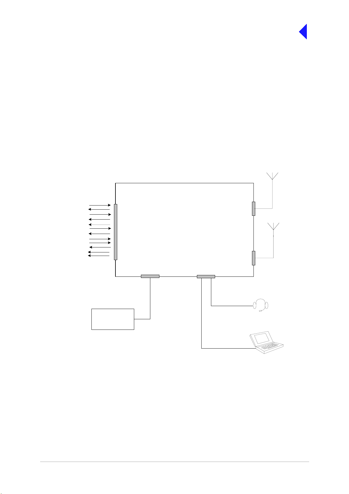
Back to Transceiver
o
Main Page
Connecting the Remote Equipment
Connection of externa l equipment dep ends on the c onfiguratio n required. The se configurati ons are as
follows:
❑ T6TR transceiver configured for local operation
❑ T6TR transceiver configured for remote operation
❑ T6TR transceiver configured for use with MARC
❑ T6TR Mode 2 configuration
❑ T6TR Mode 3 configuration.
Fig 4 to Fig 9 illustrate the various configurations.
Fig 4
Either a common Tx/Rx
antenna or separate Tx
and Rx antennas can be
T6T Transceiver
used
E-BIT
PTT relay
External VSWR
Squelch
Squelch common
Squelch defeat
Unregulated supply
Inhibit
BIT interrup tiv e test
RSSI
Ready
Tape
Facilities
Connector
Frequency Counter
required only for
maintenance
Reference
Connector
TX/RX Antenna
Connector
RX Antenna
Connector
Headset/Microphone/Diagnostics
Connector
Mic/Headset for local operation
Laptop (o r PC) requi red
nly for maintenance
Fig 4 Transceiver Configured for Local Operation
Page 7
Page 62

T6T Transceiver
Back to Transceiver
Main Page
Fig 5
Either a common Tx/Rx
antenna or separate Tx and
Rx antennas can be used
Rx Audio
Squelch
Unregulated supply
RS 422 Data
Tx Audio
PTT
Frequency Counter
required only for
maintenance
Note:
The unregulated sup ply an d R S 42 2
data connections may be used when
conn ecting to remote cont ro ll e r s
such as the Park Air T6 controller
MARC
Connector
MARC Audio
Connector
Reference
Connector
TX/RX Antenna
Connector
RX Anten na
Connector
Mic/Headset/Diagnostics
Connector
Mic/Headset for eng ineering us e
Laptop (or PC) required
only fo r maintenan c e
Fig 5 T6TR Transceiver Configured for Remote Operation
Page 8
Page 63

RSE2
Equipment
Connector 1
Rx Audio
Squelch
Unregulated supply
RS422 data
T6TR Transceiver
MARC
Connector
Back to Transceiver
Main Page
Fig 6
Either a common Tx/Rx ant enna or
separate Tx and Rx ante nnas can be
used
TX/RX Antenna
Connector
Equipment
Connector 3
Shows single channel conn ections at R SE2
Tx Audio
PTT
Frequency Counter
required only for
maintenance
Fig 6 T6TR Transceiver Configured for use with MARC
MARC Audio
Connector
Reference
Connector
RX Antenna
Connector
Headset/Microphone/Diagnostics
Connector
Mic/Headset for engineering use
Laptop (or PC) required
only for maintenance
Page 9
Page 64
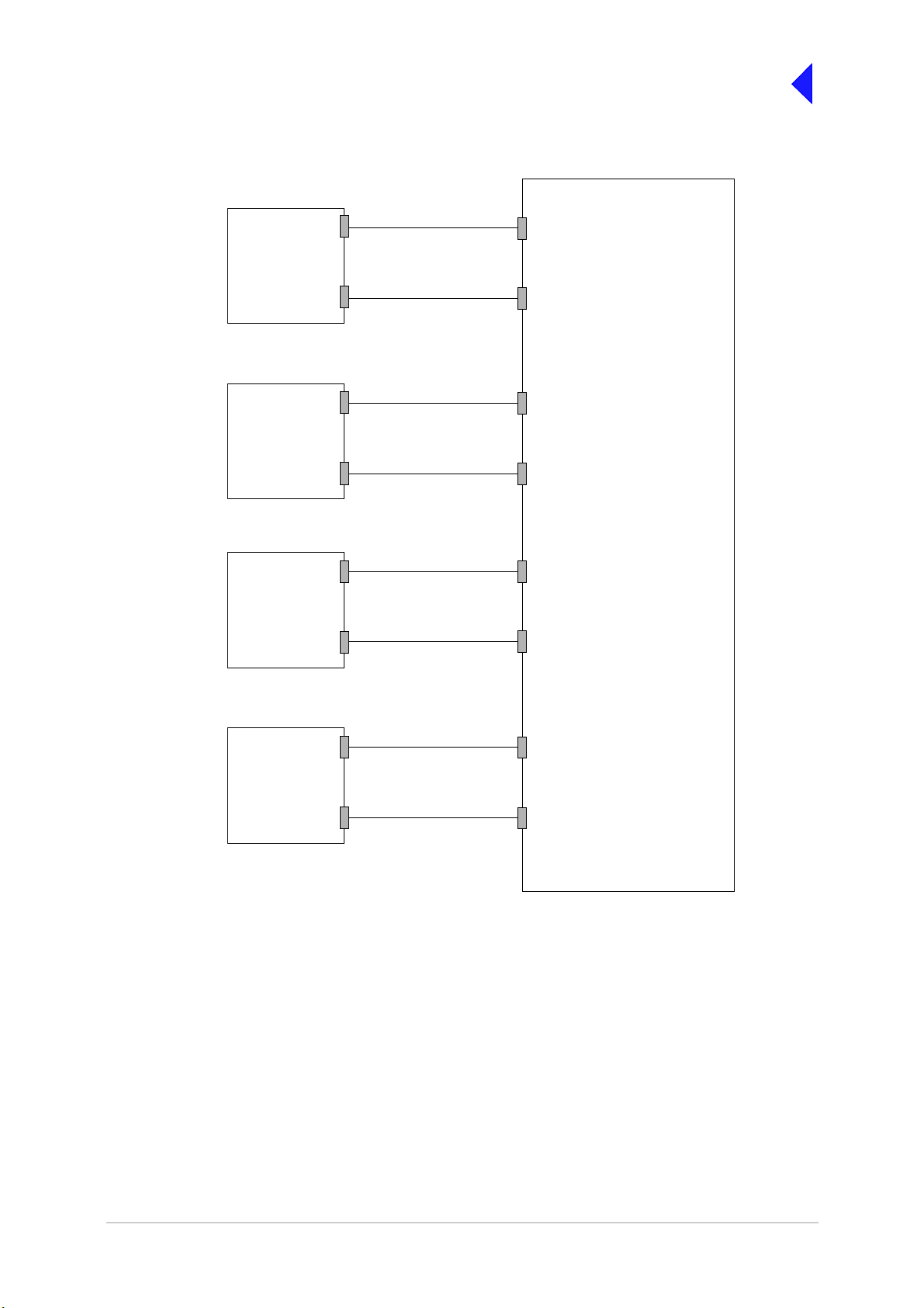
T6TR
Transceiver
MARC
Connector
MARC Audio
Connector
Fig 7
Receive lines + data
Transmit lines
Back to Transceiver
Main Page
RSE2
Equipment Connector 1
Equipment Connector 3
T6TR
Transceiver
T6TR
Transceiver
T6TR
Transceiver
MARC
Connector
MARC Audio
Connector
MARC
Connector
MARC Audio
Connector
MARC
Connector
MARC Audio
Connector
Receive lines + data
Transmit lines
Receive lines + data
Transmit lines
Receive lines + data
Transmit lines
Equipment Connector 2
Equipment Connector 4
Equipment Connector 5
Equipment Connector 7
Equipment Connector 6
Equipment Connector 8
Fig 7 Transceiver to MARC RSE2 Connections
Fig 7 sh ows the connection convention when conn ecting transceivers to a single RSE2. Table 2 and
Table 3 detail the pin to pin connections.
Page 10
Page 65

Back to Transceiver
Main Page
Table 2 Transceiver to RSE2 Equipment Conne ctor 1, 2, 5 or 6
Transceiver MARC
9-Way D-type Conn ector
Pin Number
1Ground
2 Audio line out (+) Audio line L1 2
3 Audio line out (-) Audio line L2 3
4 Squelch indication
5 Unregulated supply
6Data in (+)
7 Data in (-) Data out (-) 7
8 Data out (+)
9 Data out (-) Data in (-) 9
Table 3 Transceiver to RSE2 Equipment Conne ctor 3, 4, 7 or 8
Transceiver
output
Signal at
Signal at RSE2 RSE2 Equipment
Ground 1
Mute indication 4
Unregulated
supply input
Data out (+) 6
Data in (+) 8
Connector Pin
Number
5
Transceiver MARC RJ48
Audio Connector Pin
Number
7 Ground
4 Audio line in (+) Audio line L1 2
5 Audio line in (-)
8PTT
Signal at
Transceiver
Signal at RSE2 RSE2 Equipment
Connector Pin
Number
Ground 1
Audio line L2 3
PTT 4
Page 11
Page 66
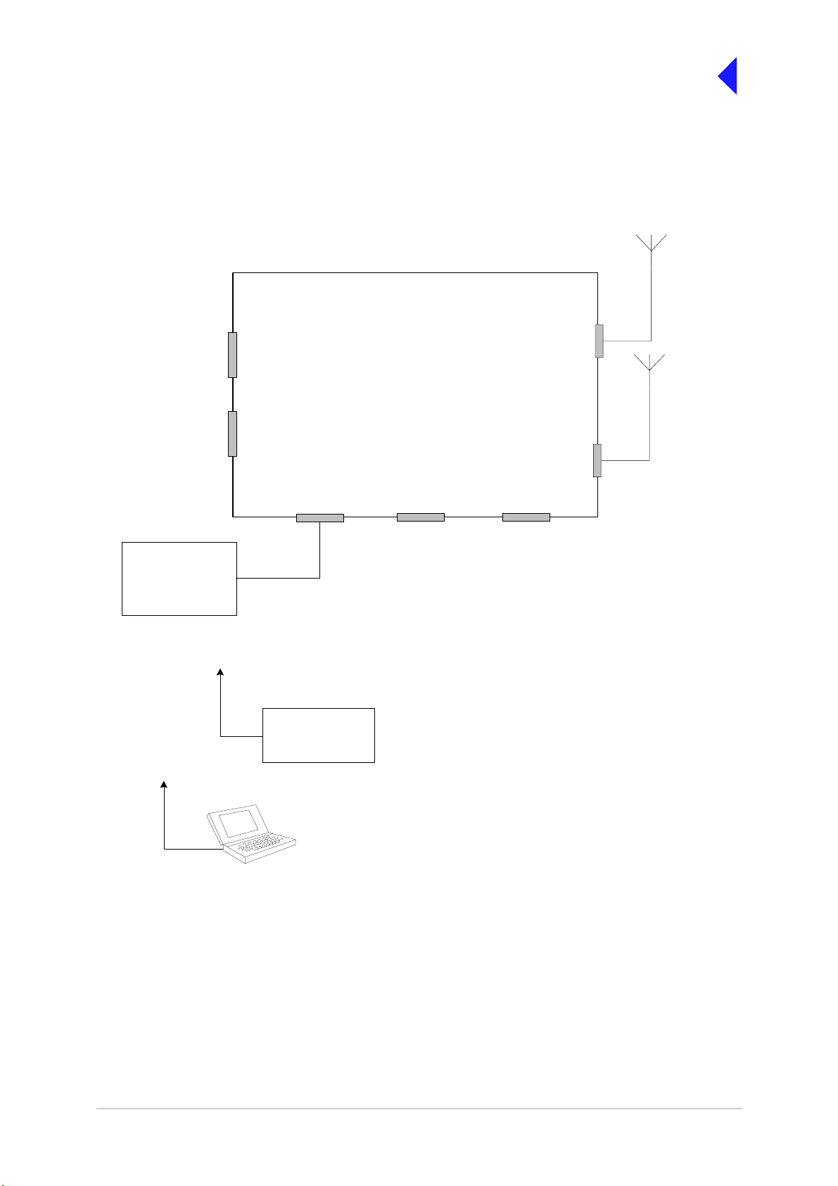
T6TR Transceiver
Reference
Connector
Headset/Microphone/Diagnostics
Connector
HDLC
Connector
Fig 8
T1/E1
Connector
Back to Transceiver
Main Page
Either a common Tx/Rx
antenna or sepa rate T x
and Rx antennas can
be used
TX/RX Antenna
Connector
RX Antenna
Connector
Facilities
Connector
Mode 2
Network Computer
Connects to the
Reference connector
Connects to the
eadset/Diagnostics
connector
Control and data
Frequency Counter
required only for
maintenance
Fig 8 T6TR Mode 2 Configuration
Page 12
Page 67
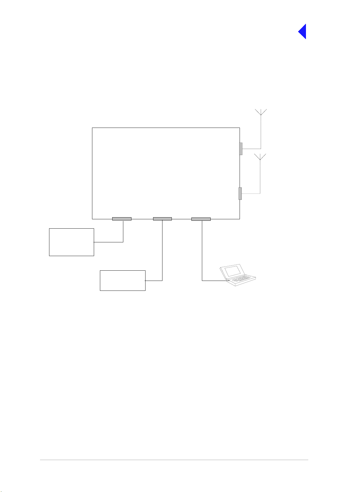
T6TR Transceiver
Fig 9
Either a common Tx/Rx antenna or
separate Tx and Rx antennas can be
TX/RX Antenna
Connector
RX Antenna
Connector
Back to Transceiver
Main Page
used
Mode 3
Network Computer
T1/E1
Connector
Control and data
Frequency Counter
required only for
maintenance
Reference
Connector
Mic/Headset/Diagnostics
Connector
Laptop (or PC) required only
Fig 9 T6TR Mode 3 Configuration
for maintenance
Page 13
Page 68

Back to Transceiver
Main Page
Connectors
Front and rear panel connector pin-outs are detailed in Table 4 to Table 11. The Reference connector is
described in text.
Front Panel Connectors
The front panel has two connectors; Headset/Microphone/Diagnostics connector and Reference
connector. These are illustrated in Fig 10.
Fig 10
Fig 10 Front Pan el
Headset/Microphone/Diagnostics Connector
The Headset/Microphone/Diagnostic connector is shown in Table 4. This connector is a self-locking
7-way DIN socket used for connecting a microphone, microphone/headset or computer.
Table 4 Headset/Microphone/Diagnostics Connector
Pin Number Signal Characteristic
1 Microphone ground 0 V
2 Transmit data (output) RS232. 1 15200baud, 8 data bits, 1 stop bit, no parity ,
no handshaking.
3 Microphone PTT (input) 0 V to PTT.
4 Receive data (input) RS232. 115200 baud, 8 data bits, 1 stop bit, no parity,
no handshaking.
5 Sidetone/headset drive
(output)
6 Microphone input (input) To ensure correct VOGAD operation, the following
7 Ground 0 V
The level is adjustable between 0and 3 V
peak-to-peak by using the volume control.
microphone input levels are required:
Passive setting: between 2 and 35 mV
Active setting: between 8 and 140 mV
Reference Connector
The Reference connector is an SMB plug used to moni tor the radio’s referen ce frequency. It monit ors
the frequency at a level of 100 mV (±50 mV) with less than -10 dBc harmonics.
Page 14
Page 69

Rear Panel Connectors
The rear panel connectors are shown in Fig 11. These connectors are:
Back to Transceiver
Main Page
❑ Antenna
❑ RX Antenna
❑ MARC
❑ MARC Audio
❑ MARC Data
❑ HLDC
❑ External Speaker
❑ Facilities
❑ ac Supply
❑ dc Supply
❑ T1/E1
Fig 11
ANTENNA
DANGER HIGH
RF VOLTAGES
CONNECT
ANTENNA
BEFORE
USE
RX
ANTENNA
INTERNALLY
( )
SELECTA BLE
T1/E1 HDLC
MARC
DATA
MARC
AUDIO
MARC FACILITIES
RATINGS
110V - 120V T4A 125V UL
CONNECTING SUPPLIES
FUSE F2
110-240V T4A 250V IEC
FUSE F1
F15A 32V
AC SUPPLY
48 - 62Hz
~ 110 - 240V ( +10%) 4A
POWER 400VA max
DC SUPPLY
21.6 - 32V 10A
SEE INSTALLATION INSTRUCTIONS BEFORE
DISCONNECT SUPPLIES WHEN NOT IN USE
SUPPLY
FUSE F1
AC SUPPLY
FUSE F2
DC SUPPLY
Fig 11 Rear Panel (Connectors)
The MARC Audio, MARC Data , T1/E1 and HLDC connectors are all RJ48 types. Fig 12 il lustrates an
RJ48 plug used with these connectors.
Pin 1
Fig 12
Numbering is shown as looking from the top of the connector.
[The top is being viewed when the lever is on the bottom.]
RJ48 Plug
Fig 12 RJ48 Modular Plug
Page 15
Page 70

Back to Transceiver
Main Page
Antenna Connectors
The antenna connectors are N-type sockets suitable for connecting 50 ohm antennas.
MARC Connector
The MARC connector is a 9-way D-type socket used for connecting to a MARC system via an RSE2. The
connector pin-out is detailed in Table 5
.
Table 5 MARC Connector
Pin Number Signal Characteristic
1 Ground 0 V
2
3
4 Squelch (output) Solid state relay, +60 to -60 V, ac or dc, 100 mA max,
5 Unregulated supply
6
7
8
9
Audio line out (+)
Audio line out (-)
(output)
Data in (+)
Data in (-)
Data out (+)
Data out (-)
Balanced 600 ohm, -20 to +20 dBm.
Phantom squelch (see Fig 14) - solid-state relay,
+60 to -60 V ac or dc, 100 mA max, configurable n/o or n/c.
Pair to pin 2.
configurable n/o or n/c.
This output is between 21.6 and 32 Vdc (nominally 24 V)
fused at 500 mA.
RS422 differential asynchronous data at 9600 baud. 8 data
bits, 1 stop bit, no parity, no handshaking.
RS422 differential asynchronous data at 9600 baud. 8 data
bits, 1 stop bit, no parity, no handshaking.
Note ...
The line level figures shown for the MARC and MARC Audio connectors are the limits when testing
the transceiver with sine wav e modula tion; the line level will be 10 dB ab ove the lin e level setting.
See the information supplied under the heading ‘Line Level Settings’ in the Operation section.
Page 16
Page 71

Back to Transceiver
Main Page
MARC Audio Connector
The MARC Audi o connector is an 8-way RJ48 socket. The connector pin-out is detailed in Table 6.
Table 6 MARC Audio Connector
Pin Number Signal Characteristic
1
2
3 Fast antenna
4
5
6 Squelch
7Ground 0 V.
8 PTT (input) Active when input dif fer s from referen ce by more than
Audio line out (-)
Audio line out (+)
changeover/PTT
Audio line in (+)
Audio line in (-)
(output)
Balanced 600 ohm -20 a nd +20 dBm. Phantom
squelch (see Fig 14) - solid-state relay, +60 to -60 V,
ac or dc, 100 mA max, configurable n/o or n/c.
Open collector NPN transistor grounding output,
200 mA max, configurable n/o or n/c.
Balanced 600 ohm input, -20 to +20 dBm.
Phantom PTT (see Fig 13) - active when input differs
from reference by more than ±10 V. Inactive when
input differs from reference by less than ±1 V.
Maximum input level ±60 V with respect to reference.
Input will draw no more than 6 mA, requires at least
1 mA to operate. Configurable active high or low.
Common reference to all inputs programmable to
+14, 0 or -14 V (±1 V).
Solid state relay, +60 to -60 V, ac or dc, 100 mA max,
configurable n/o or n/c.
±10 V. Inactive when input differs from reference by
less than ±1 V. Maximum input level ±60 V with
respect to reference. Input will draw no more than
6 mA, requires at leas t 1 m A t o o pe r ate. Con figurable
active high or low. Common reference to all inputs
programmable to +14, 0 or -14 V (±1 V).
Page 17
Page 72
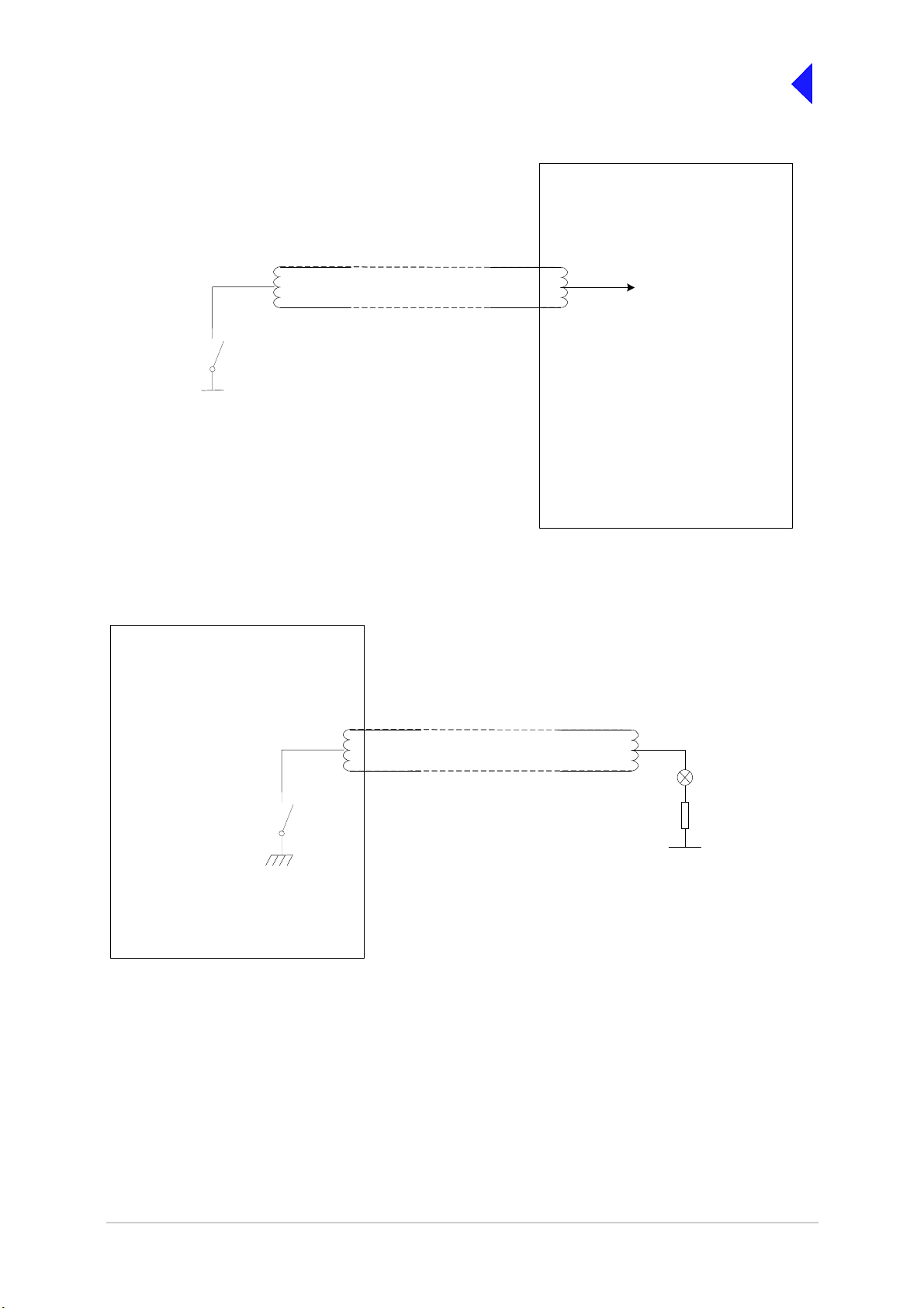
Fig 13
Back to Transceiver
Main Page
T6TR Transceiver
Solid state
relay
PTT
Maximum signal level ±60 V
with respect to transmitter
reference.
T6TR Transceiver
Audio lines with phantom PTT
signal superimposed
Internal Sensing Circuit
Reference can be configured as +14 V, 0 V
or -14 V from the Polarities screen.
With STD selected, PTT active when input
differs from reference by more than ±10 V.
PTT inactive when input differs from
reference by less than ± 1 V.
With INV selected, PTT active when input
differs from reference by less than ±1 V. PTT
inactive when input differs from reference by
more than ±10 V.
For example, to use 0 volt as the keying
potential with STD polarity, set the reference
to +14 V or -14 V.
Fig 13 Example Phantom PTT Keying Diagram
Fig 14
Solid state
relay
Relay = 100 mA maximum.
Can be configured as normally open, or
normally closed from the Polarities screen.
Fig 14 Example Phantom Squelch Indication Diagram
Audio lines with phantom
squelch signal superimposed
Squelch Indicator
R
V
The pull-up voltage should be in the
range -60 to +60 V ac or dc.
Page 18
Page 73

Back to Transceiver
Main Page
MARC Data Connector
The MARC Data connector is an 8-way RJ48 socket. The connector pin-out is detailed in Table 7.
Table 7 MARC RJ48 Data Connector
Pin Number Signal Characteristic
1
2
3 Not connected 4
5
6 Remote Supply ON/OFF
7 Ground 0 V.
8 Unregulated supply
Data in Data in +
Data out +
Data out -
(input)
(output)
RS422 differential asyn chronous da ta, 9600 baud,
8 data bits, 1 stop bit, no parity, no handshaking.
RS422 differential asyn chronous da ta, 9600 baud,
8 data bits, 1 stop bit, no parity, no handshaking.
0 V to switch off.
Note: Rear panel switch must be in ON position for
this function to operate.
This output is between 21.6 and 32 Vdc (nominally
24 V) fused at 500 mA.
T1/E1 Connector
The T1/E1 connector is an 8-way RJ48 socket used for connecting to a Mode 3 network computer. The
connector pin-out is detailed in Table 8.
Table 8 T1/E1 Connector
Pin Signal Characteristic
1 RRing
(input)
2RTip
(input)
3 Not connected 4TRing
(output}
5TTip
(output)
6 Not connected 7 Not connected 8 Not connected -
T1 - Balanced 100 ohm (±10%), 1.544 Mbits per second (±50 ppm),
AMI/B8ZS Coding.
E1 - Balanced 120 ohm (±10%), 2.048 Mbits per second (±50 ppm),
AMI/HDB3 Coding.
Protected with 28 V dif ferential and common mo de c la mp and 1.2 5 A
fuse in each line.
T1 - Balanced 100 ohm (±10%), 1.544 Mbits per second (±50 ppm),
AMI/B8ZS Coding.
E1 - Balanced 120 ohm (±10%), 2.048 Mbits per second (±50 ppm),
AMI/HDB3 Coding.
Protected with 28 V dif ferential and common mo de c la mp and 1.2 5 A
fuse in each line.
Page 19
Page 74

Back to Transceiver
Main Page
HDLC Connector
The HDLC connector is an 8-way RJ48 socket used for connecting to a Mode 2 network computer. The
connector pin-out is detailed in Table 9.
Table 9 HDLC Connector
Pin Signal Characteristic
1 HDLC RX A
(input)
RS422 differential synchronous data, 128 kbytes per second
±50 ppm.2 HDLC RX B
(input)
3 HDLC CL A
(output)
4 HDLC TX B
(output)
(output)
6 HDLC CL B
(output)
7Ground 0 V.
8 Unregulated Supply
(output)
RS422 differential synchronous data, 128 kbytes per second
±50 ppm.
RS422 differential synchronous data, 128 kbytes per second
±50 ppm.5 HDLC TX A
RS422 differential synchronous data, 128 kbytes per second
±50 ppm.
21.6 to 32 V, fused at 500 mA.
External Speaker
The External Speaker conn ector is a 3.5 mm stere o jack used for conne cting t o an e xternal speak er to
provide sidetone on the transceiver. This speaker should be a high impedance active type.
Table 10 External Speaker
Pin Signal Characteristic
Tip Speaker Drive (output) 0 to 3 V pk-pk. Connected directly to Ring.
Ring Speaker Drive (output) 0 to 3 V pk-pk. Connected directly to Tip.
Sleeve Ground 0 V.
Page 20
Page 75

Back to Transceiver
Main Page
Facilities Connector
The Facilities conne cto r is a 15 -way D-type fi ltered s ocket used fo r connec ting t o assoc iated pa rts o f a
system. The connector pin-out is detailed in Table 11.
Table 11 Facilities Connector
Pin Number Signal Characteristic
1Ground 0V.
2 E-BIT (input) An external BIT input that connects from any ancillary equipment
having a compatible BIT alarm output.
When this input is activ e, the tran sc eiver’s fron t p a nel Alarm ind ic ato r
flashes and an E-BIT message is displayed on the LCD. The input is
TTL having a 4.7 kohm pull-up resistor to 5 V. The input is
configurable from the front panel to be active high or low.
3 PTT (output) Grounding solid state relay. +60 to -60 V ac or dc, 100 mA max,
configurable n/o or n/c. Ac tivated 35 ms (± 1 ms) befo re the st art of the
power ramp up to allow for the antenna relay pull in time.
4 External VSWR (input) TTL input with 4.7 kohm pull-up to 5 V. Configurable active high or
low.
5 Squelch (output) Solid state relay linked to pin 6. +60 to -60 V ac or dc, 100 mA max,
configurable n/o or n/c.
6 Squelch common
(output)
7 Squelch defeat (input) TTL with 4.7 kohm pull-up to 5 V. Configurable active high or low.
8Ground 0 V.
9 Unregulated supply
(output)
10 Inhibit (Input) TTL with 4.7 kohm pull-up to 5 V. Configurable active high or low.
11 BIT Interruptive test
(input)
12 RSSI (output) 0 to 10 V.
13 Ready (output) Open collector NPN transistor grounding output, 200 mA max,
14 Tape (output) 0 dBm fixed output into 600 ohm for 90% modulation depth.
15 Reserved (output) Open collector NPN transistor grounding output, 200 mA max,
Solid state relay linked to pin 5.
21.6 to 32 V, fused at 500 mA.
TTL with 4.7 kohm pull-up to 5 V. Configurable active high or low.
Must be asserted for >300 ms.
configurable n/o or n/c.
configurable n/o or n/c.
Page 21
Page 76
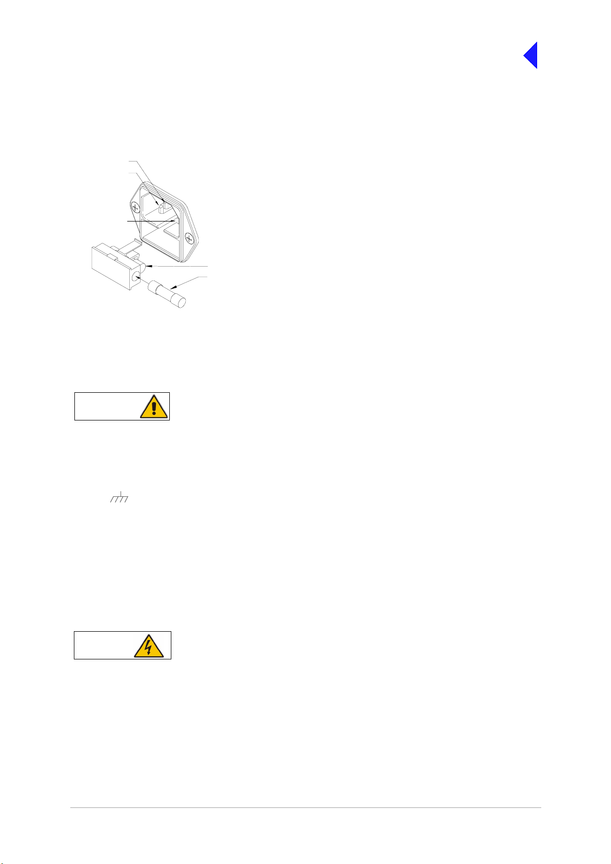
Back to Transceiver
Main Page
Fitting the Correct AC Input Fuse
The mains input fuse F2 is an integral pa rt of the rear panel a c connector (see Fig 11). The fuse type
must be correct for the local mains supply. Check the fuse fitted conforms to that detailed in Fig 15.
Fig 15
Earth
Line
For a mains input in the range 110 to 120 Vac,
Neutral
FS2
Spare Fuse
Fig 15 ac Input Fuse
fuse F2 should be rated T4A, 125V, UL.
For a mains input in the range 110 to 240 Vac,
fuse F2 should be rated T4A, 250V, IEC.
Chassis Stud Connection
WARNING Chassis Earth
A chassis stud is fitted to the transceiver's rear panel. This stud is used to connect the
equipment to the equ ipmen t r ack , o r t o t he us er's sy stem ear th poi nt. Th e s tud must no t be
used as the safety earth.
In order not to compromise the transceiver’s Electromagnetic Compatibility (EMC) the chassis stud,
marked and fitted to the rear panel (see Fig 11) must be connected to the equipment rack (if a rack
is being used) or to the user's system earth point. The connection should be made using a single tri-rated,
green-and-yellow c able having a cross-sectional are a of 2.5 mm
2
. The cable should have CSA and
UL1015 approval, and be connected to the chassis stud through an M6 eyelet (for example, Park Air part
number 20-08010103).
Failure to comply with this instruction could result in non-compliance with the European
Commission EMC Directive 89/336/EEC.
AC Supply Connection
WARNING Dangerous Voltages
The equipment is permanently connected to the mains supply when the mains connector is
attached. Switching the rear pan el Power switch to off does not isolate all internal circuits
from the mains supply. For this reason, a mains isolating switch should be fitted close to,
and easily accessible from, the transceiver's position. The isolation switch should isolate
both live and neutral supplies, be clearly labelled, and adequately rated to protect the
equipment.
Page 22
Page 77

Back to Transceiver
Main Page
WARNING Earth Connection
This equipment must be earthed. The earth terminal of the ac connector should be used as
the safety earth.
An ac input connector (see Fig 11 and Fig 15) is fitted to the equipme nt’ s r ear pane l. T he c able us ed to
connect between the equipm ent and the user’s ac power source shoul d be 3-core (to IEC 227) rated
250 Vac at 8 amps, and have a minimum cross-sectional area of 1.0 mm
2
per core. Park Air recommends
the use of polyvinyl chlo ride (PVC) insulated cable. The cable must be fi tted with the IEC approved
equipment connector (Park Air part number 20-02030102) supplied with the transceiver, and conform to
the following specification:
❑ If PVC insulated, be no t lighter than ordinar y polyviny l chlorid e sheathed fl exible c ord accord ing
to IEC publication 227 (designation H05 VV-F, or H05 VVH2-F).
❑ If rubber insulated, be of synthetic rubber and n ot lighter than ordinary toug h rubber-sheathed
flexible cord accordin g to IEC publi cation 24 5 titled ‘Rub ber Insulate d Cables of Rated V oltages
up to and Including 450/750 V (designation H05 RR-F)’.
The T6TR transceiver is a Class 1 equipment. The ac sup ply cable should have a green-an d-yellow
protective earthing conductor electrically connected to the protective earthing terminal of the equipment
connector and the mains plug. Park Air recommends the ac supply cable is colour coded in accordance
with the electrical appliance (colour code) regulations for the UK. That is:
❑ The core coloured green-and-yellow must be connected to the terminal in the plug that is marked
with the letter E or by the earth symbol or coloured green-and-yellow.
❑ The core coloured b lue must be connected to the termin al that is marked with the letter N or
coloured black.
❑ The core coloured brown m ust be connected to the termin al that is marked with the letter L or
coloured red.
DC Supply Connection
The transceiver ope rates from eithe r an ac, or a dc input supp ly. When both ac and dc are co nnecte d,
operation from the ac supply takes priority; automat ic change-over to the dc supp ly occurs if the ac
supply fails. On restoration of the ac supply, the equipment reverts to ac operation.
A dc input supply connector (see Fig 11) is fitted to the equipment's rear panel. The recommended
minimum rating of the dc supply cable is: 2-core having a cross-sectional area of 1.5 mm
2
per core. The
supply cable should be fitted with an XLR3 connector (Park Air part number 20-01030106).
Page 23
Page 78

Switching On
Back to Transceiver
Main Page
WARNING
Dangerous Voltages
When the POWER SWITCH is set to the Standby position, dangerous voltages are still present in
the transceiver's internal power supply circuitry. To ensure safe working, the transceiver must be
isolated from the ac and dc input supplies.
When installatio n is complete, the transceiver shoul d be switched on at the rear panel 2-way r ocker
Power switch. The Power switch is used to switch on, and switch off, power to the transceiver's circuitry
but does not remove power from the radio.
= Standby= On
Under normal circumstances this screen is displayed when the radio is switched on.
T 6 D i g i t a l R a d i o
( c ) 2 0 0 3 P a r k A i r
I n i t i a l i s i n g . . . .
. . . . . . . . . . . . . . .
The bottom row begins empty and dots are added as the initialisation progresses. When the initialisation
is complete the Main Screen is displayed.
Note ...
All radios have a standby function to extend power supply life when the radios are not required to be
operational. With the st andby fun ction enable d the tr ansceiv er is un able to tr ansmit or receiv e and
the display is blank. Rem ote control ser ial ports and the fr ont panel contro l knob remain active to
allow normal operation to be restored.
Page 24
Page 79

Back to Transceiver
Main Page
End of Document
Page 25
Page 80

Back to Transceiver
Main Page
Page 26
Page 81

Maintenance
Back to Transceiver
Main Page
This document gives the maintenance procedures applicable to the
T6TR VHF Multimode Transceiver.
Part 1 General Information
Part 2 Maintenance Procedur es
Part 3 Virtual Front Panel
Page 1
Page 82

Back to Transceiver
Main Page
General Inform ation
This section pr ovides the m aintenance personnel wi th sufficient information to maint ain and repa ir the
T6TR VHF transceiver. The standard maintenance policy regards the transceiver as a Line Replacement
Unit (LRU) which should be changed for a serviceable unit should a failure occur. Note that modules may
be changed on the advice of Park Air Customer Support (see following contact details).
Email address: Support@uk.parkairsystems.com.
Telephone during normal hours: From UK 01778 381557 or from outside UK 44 1778 381557.
Telephone out of normal hours: From UK 07733 124457 or from outside UK 44 7733 124457.
Caution ...
When replacing a Processor module ensure the correct module is fitted.
❑ For radios at Mod Strike Level 5 the Processor Module part number is 68-60000671/F
(board issue 5).
❑ For radios at Mod Strike Level 7 the Processor Module part number is 68-60000671/H
(board issue 7).
❑ Note that Mod strike 6 was a special to type modification.
The following provides information that enables the user to:
❑ Conduct scheduled maintenance tasks including checking/setting the reference frequency
oscillator to compensate for long term ageing effects
❑ Identify any tools or test equipment required to maintain the transceiver
❑ Use the built-in test facilities to check transceiver functionality
❑ Remove a transceiver from service to dismantle and replace a faulty module, and where
applicable, realign the module
❑ Install the Virtual Front Panel (VFP) software into a PC
❑ Use the VFP to:
❑ Download all radio settings to a file that can be stored/printed for reference
❑ Change radio settings
❑ Copy settings from one radio to another
❑ Check a radio after repair and return it to service.
Refer to the Installati on and Operating sections, available fr om the Main page of this document, for
complete installation and setting up procedures.
Included on the CD-ROM delivered with the radio is the VFP software. The software enables the original
settings to be re-loaded and alignment to be made if the transceiver's Processor, PA Control and
PA modules are ever repla ced. The VFP so ftware can be run from this doc ument by clic king on ‘B ack
to Transceiver Mai n Page’ ( at top r ight of page) and f rom the re, c licking on ‘Bac k to Mai n Page ’ (at t op
right of page). When the Main page is displayed select ‘Run the VFP Software’.
Note ...
A hard copy of the User Documentation is available. Contact Park Air for details.
Page 2
Page 83

Back to Transceiver
Main Page
Transceiver Variants
Two variants of the T6TR VHF transceiver are available:
❑ B6550/NB/50. This trans ceiver frequency operating range is 118.000 to 136.975 MHz. Power
output adjustable from 5 to 50 Watts. Frequency stability compliant with ICAO requirements for 2,
3 and 4-offset carrier applica tio ns
❑ B6550/WB/50. This tr ansceiver frequency operating range is 112.000 to 155.975 MHz . Power
output adjustable from 5 to 50 Watts. Frequency stability compliant with ICAO requirements for 2,
3 and 4-offset carrier applica tio ns.
Operating Frequency
The transceiver’ s op er ati ng frequ enc y c an be changed by the user throug h the fr ont pa nel , t hr oug h t he
VFP, through a T6 controller or through an associated MARC system (or compatible control data
system). Details of how to ch ange the operating frequen cy from th e front panel and VF P are conta ined
in this document. Details of how to change the frequency from MARC or a T6 controller can be found in
the MARC and T6 Controller User Guides respectively.
Input Supplies
The transceiver can be operated from standard ac input supplies, or from a low voltage dc supply. Both
ac and dc input supplies can be connected to the equipment. When both ac and dc supplies are
connected, operation from the ac supply takes priority; automatic change-over to the dc supply will occur
if the ac supply fails. On restoration of the ac supply, the equipment reverts to ac operation.
Built-in Test (BIT) Indications
The transceiver continuously self monitors key internal parameters without affecting normal operation. If
a BIT alarm is detected, the front panel Alarm indicator lights, the Ready indicator becomes unlit, and the
transceiver becomes inoperable. Additionally, a BIT alert, as opposed to a BIT alarm may be indicated.
A BIT alert is shown b y the front p anel Al arm indi cator flash ing; the Ready i ndica tor remai ns lit and the
transceiver remains operational, but at reduced power. Conditions that cause a BIT alert are:
❑ RF output has reduced from its setting by more than 3 dB
❑ Supply volts has fallen below a pre-defined level.
In AM-voice and AM-MSK modes only, and in addition to continuous monitoring, an interruptive BIT test
can be initiated locally at the front panel or remotely. When initiated, test signals are injected that key the
transceiver allowing parameters to be monitored in their active state.
The results of continuous monitoring, and of interruptive testing, are available at the front panel LCD and,
if connected, the VFP PC. When the transceiver is used with a MARC system (or other compatible data
and control system) the results are also sent, in the form of a data message, to the monitoring facility.
Page 3
Page 84

Back to Transceiver
Main Page
Configurations
The connectors used to configure the transceiver depend on the required operating mode. The purpose
of each connector is detailed in the following text. Config uration detai ls can be f ound in the In stallation
section of this document.
Antenna Connector Used in all operating modes to connect the 50 ohm antenna
feeder cable.
Headset/Microphone/Diagnostics This is a dual purpose connector. A microphone/headset
Connector(complete with integral PTT switch) can be connected
to enable
local AM-voice operation. Alternatively, a PC can be connected to
allow use of the VFP. The VFP can be used to set the
transceiver's operational settings, or to download new software.
Reference Connector Used in all operating modes to check and reset the transceiver's
reference frequency.
Facilities Connector Used primarily to connect remote signals when using AM-voice
mode and the transceiver does not form part of a MARC system.
Some auxiliary signals available at this connector, for example
the 24 volt (nominal) unregulated output supply, can be utilized
irrespective of the operating mode.
MARC Port The MARC port is used to connect received audio, squelch
indication and data to a MARC system via an RSE2.
MARC Audio The MARC Audio port is used for connecting transmit audio and
PTT to a MARC system via an RSE2.
MARC Data The MARC Data port is used for connecting data to a MARC
system.
T1/E1 The T1/E1 port is an 8-way RJ48 socket used for connecting a
Mode 3 network computer.
HLDC The HLDC port is an 8-way RJ48 socket used for connecting a
Mode 2 network computer.
Page 4
Page 85

Back to Transceiver
Main Page
Maintenance Procedures
WARNING Dangerous Voltages
The instructions given in this section involve connecting dangerous voltages to the
transceiver. The instructions detailed in this document must be carried out only by suitably
qualified personnel.
When an ac supply is connected, lethal voltages are present within the transceiver. Care
must be taken by personnel to avoid accidental contact with exposed circuitry during
maintenance or alignment procedures.
When the power switch is set to the off position, lethal voltages are still present in the
transceiver's internal power supply circuitry. To ensure safe working, the ac and dc input
supplies must be disconnected from the transceiver.
WARNING
The antenna used with the transceiver must be installed such that the resultant radiated field
strength is below 10 W/m² in areas normally accessible to personnel.
Caution
The T6TR transceiver’s circuitry contains Electrostatic Sensitive Devices (ESSDs).
Personnel must be aware of the precautions necessary to prevent damage to such devices.
Caution Unauthorized Modifications
Changes or modifications made to this equipment that are not expressly approved by
Park Air, or parties authorized by Park Air, could void the user ’s authority to operate the
equipment.
Caution Repairs
Antenna Radiation
ESSDs
(1) When carrying out repairs to the PA module, care must be taken not to damage the gasket.
If the strips become damaged, they must be replaced. Failure to comply with this
instruction may compromise the transceive r’s Electromag netic Compatibil ity (EMC) and
breach European Commission regulations.
(2) When screws are inserted into the transceiver PA casting care must be taken not to
exceed a torque of 6 Ibs/in ch when tightening . This applies when r eplacing the top and
bottom covers and during the refitting of the PA module.
Page 5
Page 86

Back to Transceiver
Main Page
Introduction
This part of th e Maintenance section covers maintenance tasks that include schedule maintenance,
dismantling and assembly instructions and fault finding. Due to the complexity of most modules the
recommended policy is repair by replacement of the radio. However module replacement information is
supplied in the event that Park Air Customer Support advises this may be done.
A faulty module may be traced by aid of the front panel LCD and Scroll/Select control; VFP or MARC.
Note ...
Access to a PC is essential when fitting spares.
During all maintenance tasks the warnings and cautions given in this section should strictly be adhered to.
For maintenance purposes and loading new software, a Virtual Front Panel (VFP) is used. The VFP is a
standard PC loaded with a bespoke software package for carrying out these tasks. Separate VFP
operational instructions are included in Part 3 of this section of the document.
Tools, Materials and Test Equipment Required
The following tools, materials and test equipment should be made available to complete the maintenance
tasks described in this section:
❑ Personal Computer (PC)
❑ General Pu rpose Toolkit (including a
1.5 mm Allen key)
❑ 6BA Nut Spinner
❑ Camel Hair Brush
❑ Clean Lint-free Cloths
❑ Frequency Counter
❑ Power Meter
❑ Dummy Load
❑ PC to Radio Interconnection Lead
(Park Air part number 17E12600001)
Scheduled Maintenance
Park Air recommends that this is carried out at twelve-monthly intervals. Schedule maintenance
comprises:
(1) Ensuring the equipment is clean (see page 7).
(2) Ensuring that the external connectors are securely fitted to the transceiver (see page 7).
(3) Checking and resetting (if required) the transceiver's frequency standard (see page 7).
(4) Performing a BIT interruptive test (see page 7).
(5) Performing an ac and dc change-over check (see page 9).
Page 6
Page 87

Back to Transceiver
Main Page
Schedule Maintenance Procedure
The procedure, detailed in the following paragraphs, should be followed whe n carrying out schedule
maintenance.
Cleaning the Equipment
Remove all dust a nd di rt from the e quipm ent's e xterior using the clean ing c loths a nd ca mel h air brush.
Clean the front panel indicators and LCD face.
Security of External Connections
Check all external connections are secure and free from damage.
Setting the Transceiver’s Internal Reference Frequency
To set the transceiver’s inte rn al refer ence fr equ enc y, use the fol lo win g pr ocedure. Note that references
to the switch in the procedure mean the Scroll/Select switch.
(1) Refer to AM-Voice Mode Settings
Screen in the Operation s ection of this
document and set the offset to 0 kHz.
(2) Select Exit and return to the Main
screen.
(3) Connect a high impedance frequency
counter to the front panel Reference
connector.
(4) From the M ain scre en, pre ss the swi tch
to display the Contro l screen. Turn the
switch until Settings is highlighted.
Press the switch.
(5) Ensure the Settings screen is displayed.
Turn the switch until Ref Freq is
highlighted, th en pre ss t he switch .
(6) With Ref Freq selected turn the switch
clockwise or anti-clockwise until the
frequency counter reads 20.950000 MHz
±10 Hz, then press the switch.
(7) Turn the switch clockwise until Exit is
highlighted, then press the s witch. You
are returned to the Main screen.
AM-Voice Mode Settings Screen
A N T C / O D e l
O f f s e t 0 . 0 k H z
S q u e l c h - 1 0 7 d B m
E x i t < < > >
Control Screen
F r e q u e n c y
C h a n n e l
S e t t i n g s
E x i t
Settings Screen
B a n d E d g e s
R e f F r e q 5 0 . 0 %
B a c k l i g h t 0 3 0 s
E x i t < < > >
(8) Disconnect the frequency counter.
(9) Refer to AM-Voice Mode S ettings Screen in the Operation se ction of this doc ument and set to
the required offset.
To Initiate a BIT Test
Use the following procedur e to initiate an interrup tive BIT test from the transceiver's fro nt panel. A BIT
test cannot be initiat ed while the transceiver is keyed. An interru ptive BIT test cannot be initiated in
Mode 2 or Mode 3.
Page 7
Page 88

Back to Transceiver
Main Page
During an interruptive BIT test, the transceiver radiates modulated carrier waves at the set
power. Users should therefore obtain the necessary authority before initiating a test.
If the test is to be carr ied out with the ant enna disconn ected, ensure a lo ad is fitted to the
transceiver's Antenna (not Rx Antenna) connector.
In order to test the line input stages, an internally generated 1 kHz tone is injected into the
line input circuit. Any other audio present on the line input will cause the test to be
inaccurate. Therefore the transceiver must not be keyed during the test.
(1) From the Main screen, press the switch to
display the Control screen. Turn the switch
until BIT is highlighted. Press the switch.
(2) Ensure the BIT menu is displayed. Turn the
switch until BIT Initiate is highli ghted. Press
the switch.
B I T
S / W C o n f i g
S t a n d b y
E x i t < <
B I T I n i t i a t e
E T I 0 0 0 0 0 : 0 0 h r s
A C S u p p l y O N
E x i t > >
(3) During the test, which takes approximately
two seconds, the Testing screen is
displayed.
T e s t i n g
P l e a s e W a i t
On completion, and if the interruptive test was initiated from the front panel, one of the following screens
will be shown.
(4) Selecting OK takes the user back to the BIT
screen.
.
(5) Selecting OK takes the user back to the BIT
screen. The user can then scroll through the
screen to check out transceiver parameters
for failure.
T e s t S t a t u s
P A S S
O K
T e s t S t a t u s
F A I L
O K
Page 8
Page 89

Back to Transceiver
Main Page
AC and DC Change-over Check
If both ac and dc input supplies are connected to the transceiver, carry out the following check:
(1) Confirm that both ac and dc supplies are connected to the transceiver. Ensure that the rear panel
Power switch is set to the I (on) position.
(2) Confirm that the front pa nel Rea dy ind icato r is li t, the LCD i s illum inated , and the transc eiver i s
operational.
(3) Switch off the ac supply from its source.
(4) Check that the tra nsceiver continues to operate correctly from the dc supply. If accessed, the
front panel BIT scree n will show AC Supply as of f and DC supply as on. The value of the dc
supply is also shown.
Page 9
Page 90

Back to Transceiver
Main Page
Dismantling and Assembly Instructions
Introduction
This topic provides the user wi th de tailed instru ction s on the rem oval and r eplacem ent of mo dules a nd
assemblies. Access to a PC loaded with VFP software, and a radio to PC se rial interconnection lea d,
Park Air part number 17E12600001 is essential when carrying out these instructions.
The transceiver’s m odules and assem blies are acce ssed by removi ng the top and bottom co vers. The
top cover is secur ed by 18 countersunk screws a nd the bottom cover by 15 co untersunk screws. To
remove a module fr om th e tran sceiv er, fo llow th e instr uctio ns de tailed in the fo llowi ng par agraphs (see
Fig 3 for module locations when covers are removed).
Cautions ...
(1) When removing or refitting modules, observe antistatic handling precautions.
(2) Do not change any potentiometer (or link) settings unless detailed in these instructions.
Potentiometers have been set using specialist equipment.
(3) The transceiver uses the following Molex KK connectors:
CN2 on the PA Control/Rx RF module
CN7 and CN6 on the PSU Regulator module
CN3 on the Front Panel PCB.
To remove KK type connectors:
❑ Free the locking mechani sm on the c onn ect or by mo ving one side of the connector up, then
move the other side up (see the following diagram). The upward motion should only be as far
as needed to free the locking mechanism.
❑ DO NOT pull the cable to free the connector.
❑ Note that KK type connecto rs are des ig ned to be rem ov ed in this man ner to fre e the l ocki ng
mechanism. Do not use this procedure with non-KK type connectors as damage to the
connector may occur.
Lift 2Lift 1
PCB
Top Cover
To remove the to p cov er, loca te and unsc rew t he 18 count ersu nk scr ews secu ring the to p cover to t he
mainframe. Access can then be gained to the following modules:
❑ Processor module
❑ PSU Regulation module
❑ Power Supply (requires both top and bottom covers to be removed)
❑ Front Panel assembly (requires both top and bottom covers to be removed).
WARNING Dangerous Voltages
Dangerous voltages are pr esent w ithin the t ranscei ver. Care must be tak en by p ersonne l to
avoid accidental contact with exposed circuitry when the top cover is removed and power is
applied to the radio.
Page 10
Page 91
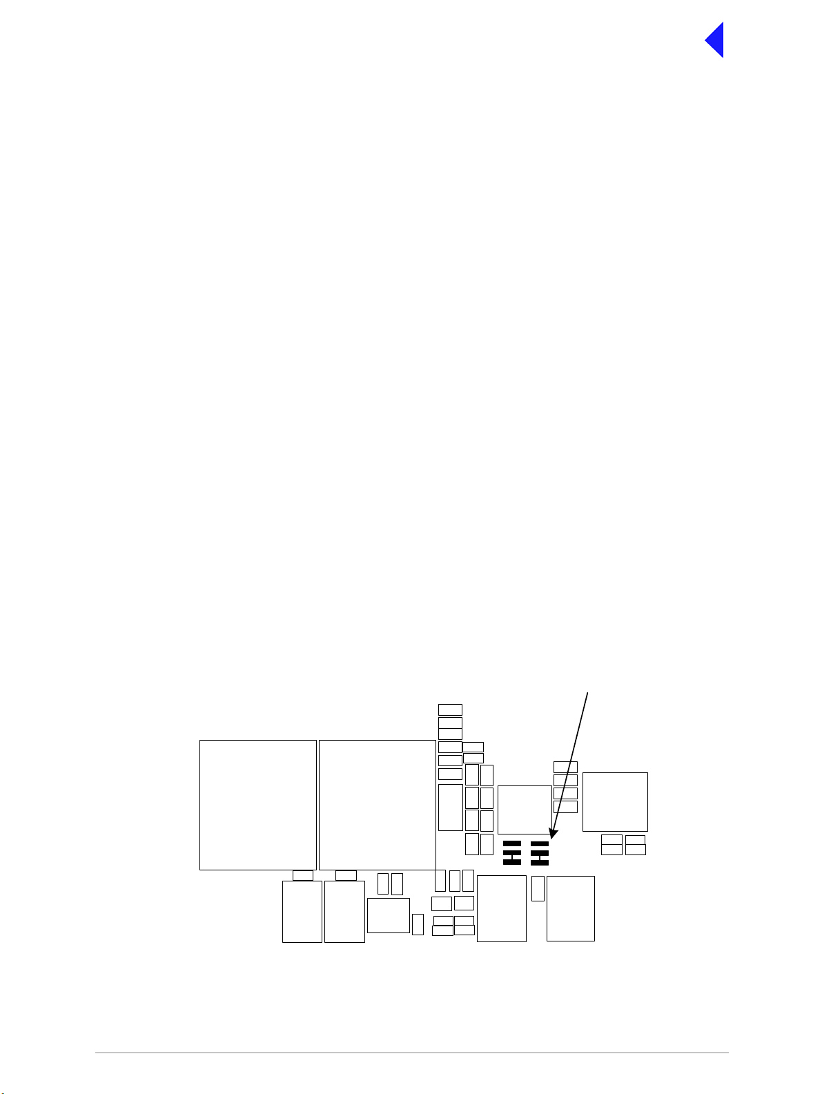
Back to Transceiver
Main Page
Removing and Refitting the Processor Module
The Processor module is located as shown in Fig 3. A module removal diagram is shown in Fig 4.
Removal
Before attempting to remov e the Processor module, and if possi ble, save the equipment settings. T o
achieve this connect a PC, with the VFP software loaded, to the radio using the PC to Radio
Interconnection Lea d (Park Air part numb er 17E12600001). With the VFP software activ e, upload the
radio settings to a specified file.
Ensure that the transceiver is isolated from the ac and dc input supplies. Then proceed as follows:
(1) Remove the transceiver’s top cover as described on page 10 (take heed of the warning).
(2) Locate the Processor module and disconnect the following connectors:
❑ CN1 50-way connector (50-way ribbon cable from PA Control/Rx RF module)
❑ CN3 14-way connector (14-way ribbon cable from PSU Regulator module)
❑ CN4 34-way connector (34-way ribbon cable from Front Panel module)
❑ CN2 SMB connector (to PA Control/Rx RF module).
(3) Gain access to the rear of the transceiver. Using a 6BA nut spinner tool, remove the four
screwloc 8 mm-4-40 UNC screws that secure t he Proces sor module interfac e connectors CN5
and CN6 to the rear panel.
(4) Remove the 11 (Mod Strike 5 modules), 7 (Mod Strike 6 and 7 modules) M3 x 8 mm screws that
secure the module to the transceiver’s mainframe.
(5) Remove the module from the chassis.
Refitting
To refit the Processor module, proceed as follows:
(1) Place the module in positi on. E nsu re no wir es are tra ppe d by the mod ule . Ens ure jumper J2 on
the module is set to ‘R/TR’ for transceiver (see diagram on this page).
JP2
Shown set for
Transceiver
T2
T3
TS7
C84
T
R/TR
T
R/TR
IC38
IC20IC19
IC21
IC25
IC27
(1) Ensure the module’s int erface connecto rs CN5 and CN6 are located co rrectly and are ali gned
with the screw holes in the rear panel. Fit the four screwloc 8 mm-4-40 UNC screws and wav y
washers but leave them loose.
Page 11
Page 92

Back to Transceiver
Main Page
(2) Fit the 11 (Mod Strike 5 modules), 7 (Mod Strike 6 and 7 modules) M3 x 8 mm screws that secure
the module to the transceiver’s mainframe, but leave them loose.
(3) Using a nut spinner tool, tighten the four screwloc 8 mm-4-40 UNC screw s and wavy washers
that secure the connectors; then ti ghten the 11 (Mod Strik e 5 modules), 7 (Mod Strike 6 and 7
modules) M3 x 8 mm screws that secure the module to the receiver’s mainframe.
(4) Refit the following connectors to the module:
❑ CN1 50-way connector (50-way ribbon cable from PA Control/Rx RF module)
❑ CN3 14-way connector (14-way ribbon cable from PSU Regulator module)
❑ CN4 34-way connector (34-way ribbon cable from Front Panel module).
(5) Re-establish the ac and/or dc supplies (take heed of the warning on page 10).
(6) Switch power on at the radio using the rear mounted Power switch.
(7) Ensure the front panel Ready indicator is lit and the Alarm Indicator is unlit.
(8) If a new module has been fitted, connect the VFP PC to the radio using the PC to Radio
Interconnection Lead, Par k Air p art number 17E12 600001 (if not alrea dy con nected ). Note that
any module sent from Park Air as a spare for a particular radio will be programmed with
compatible operat ing and F ill softwar e. Park Air k eeps recor ds of modu le softwar e in all rad ios
supplied. Care must be taken when using a module removed from another radio as this module
may not have compatible software.
(9) If saved during the removal procedure, download the radio settings from file using the VFP (see
VFP information starting on page 21). Alternatively the settings can be edited by hand as
described in the Operation section of this document. Once entered, ensure the required settings
appear in the VFP screen.
(10) Carry out the Calibrate routine using the Virtual Front Panel (VFP), as detailed in the procedure
To Calibrate the Transceiver on page 26.
(11) Carry out a BIT interruptive test as detailed in the procedure To Initiate a BIT Test on page 7.
(12) Remove the VFP PC to radio interconnection lead and switch power off at the transceiver using
the rear mounted Power switch. Isolate the transceiver from the ac and/or dc supplies.
(13) Refit the transc eiver’s top cover ( take note of repairs caution (1 ) on page 5 before carrying out
this task). The transceiver can now be returned to service.
Page 12
Page 93

Back to Transceiver
Main Page
Removing and Refitting the PSU Regulator Module
The PSU Regulator module is located as shown in Fig 3. A module removal diagram is shown in Fig 5.
Removal
Before attempting to remove the PSU Regulator module, ensure that the transceiver is isolated from the
ac and dc input supplies. Then proceed as follows:
(1) Remove the transceiver’s top cover as described on page 10 (take heed of the warning).
(2) Locate the PSU Regulator module and remove the three M3 x 8 mm captive washer screws that
secure the module to the transceiver’s mainframe.
(3) Carefully raise the module to gain access to the module connectors.
(4) Disconnect the following connectors:
❑ CN5 10-way connector (10-way ribbon cable to PA Control/Rx RF module)
❑ CN6 6-way connector (2-way loom to power supply). Note caution (3) on page 10
❑ CN4 14-way connector (14-way ribbon cable to Processor module)
❑ CN3 3-way connector (3-wire loom to PA module)
❑ CN7 3-way connector (3-wire loom to rear panel On/Off switch). Note caution (3) on page 10
❑ CN2 2-way connector (2-wire loom from dc input connector on rear panel)
❑ CN1 4-way connector (4-wire cable from power supply)
❑ CN9 2-way connector (2-wire cable ac input to power supply)
❑ CN8 3-way connector (2-wire loom to rear panel ac input connector plus chassis connection).
(5) Remove the module from the chassis.
Refitting
To refit the PSU Regulator module, proceed as follows:
(1) While holding the module in position, connect the following connectors:
❑ CN8 3-way connector (2-wire loom to rear panel ac input connector plus chassis connection)
❑ CN9 2-way connector (2-wire cable ac input to power supply)
❑ CN1 4-way connector (4-wire cable from power supply)
❑ CN2 2-way connector (2-wire loom from dc input connector on rear panel)
❑ CN7 3-way connector (3-wire loom to rear panel On/Off switch)
❑ CN3 3-way connector (3-wire loom to PA module)
❑ CN4 14-way connector (14-way ribbon cable to Processor module)
❑ CN6 6-way connector (2-way loom to power supply)
❑ CN5 10-way connector (10-way ribbon cable to PA Control/Rx RF module).
(2) Locate the module in position. Ensure no wires are trapped by the module.
(3) Secure the module t o the transceive r’s mainframe using the three M3 x 8 mm capti ve washer
screws removed during the removal procedure.
(4) Re-establish the ac and/or dc supplies (take heed of the warning on page 10).
(5) Switch power on at the radio using the rear mounted Power switch.
(6) Ensure the front panel Ready indicator is lit and the Alarm indicator is unlit.
(7) Carry out a BIT interruptive test as detailed in the procedure To Initiate a BIT Test on page 7.
Page 13
Page 94

Back to Transceiver
Main Page
(8) Switch power off at the transceiver using the rear mounted Power switch. Isolate the transceiver
from the ac and/or dc supplies.
(9) Refit the transceive r’s top c over (take n ote of rep airs cauti on (1) on page 5 before carrying out
this task). The transceiver can now be returned to service.
Bottom Cover
To remove the bottom cover, locate and unscrew the 15 captive screws securing the bottom cover to the
mainframe. Access can then be gained to the following modules:
❑ PA Control/Rx RF module
❑ Power supply (requires top and bottom covers to be removed)
❑ PA module (requires top cover and bottom covers to be removed)
❑ Front Panel assembly (requires top cover and bottom covers to be removed).
WARNING Dangerous Voltages
Dangerous voltages are pr esent w ithin the t ranscei ver. Care must be tak en by p ersonne l to
avoid accidental contact with exposed circuitry when the bottom cover is removed and
power is applied to the radio.
Removing and Refitting the PA Control/Rx RF Module
The PA Control/Rx RF module is located as shown in Fig 3. A module removal diagram is shown in Fig 6.
Removal
Before attempting to remo ve th e PA Control /Rx RF mo dule, en sure that the transceiver is isol ate d from
the ac and dc input supplies.
Then proceed as follows:
(1) Remove the transceiver’s bottom cover as described above (take heed of the warning).
(2) Locate the module and disco nnect the following conne ctors (before removin g CN7 and CN12,
note the antenna configuration):
❑ CN1 50-way connector (50-way ribbon cable from Processor module)
❑ CN6 10-way connector (10-way ribbon cable from PSU Regulator module)
❑ CN5 SMB connector (reference frequency)
❑ CN3 SMB connector (RF drive)
❑ CN4 SMB connector (forward power sense)
❑ CN2 6-way connector (to PA module). Note caution (3) on page 10)
❑ CN8 SMB connector (to Processor Module)
❑ CN7 SMB connector from the Rx antenna connection or CN13 on the PA module (see
antenna configuration on page 16)
❑ CN12 SMB connector (connects to CN13 on the PA module) or Rx antenna connection (see
configuration on page 16).
(3) Remove the seven M3 x 8 mm captive washer screws that secure the module to the transceiver’s
mainframe.
(4) Remove the module from the chassis.
Page 14
Page 95

Back to Transceiver
Main Page
Refitting
To refit the PA Control/Rx RF module, proceed as follows:
(1) Place the module in position. Ensure no wires are trapped by the module.
(2) Fit the seven M3 x 8 captive washer screws that secure the module to the transceiver’s
mainframe.
(3) Refit the following connectors to the module:
❑ CN7 SMB connector to the Rx antenn a connection or to the connecto r from CN13 on the
PA module (see antenna configuration on page 16)
❑ CN12 SMB connector to the CN13 on the PA module or Rx antenna connection (see
configuration on page 16)
❑ CN8 SMB connector (to Processor Module)
❑ CN2 6-way connector (to PA module)
❑ CN4 SMB connector (forward power sense)
❑ CN3 SMB connector (RF drive)
❑ CN5 SMB connector (reference frequency)
❑ CN6 10-way connector (10-way ribbon cable from PSU Regulator module)
❑ CN1 50-way connector (50-way ribbon cable from Processor module).
(4) Re-establish the ac and/or dc supplies (take heed of the warning on page 14).
(5) Switch power on at the radio using the rear mounted Power switch.
(6) Ensure the front panel Ready indicator is lit and the Alarm indicator is unlit.
(7) Carry out the Calibrate routine using the Virtual Front Panel (VFP), as detailed in the procedure
To Calibrate the Transceiver on page 26
(8) Carry out a BIT interruptive test as detailed in the procedure To Initiate a BIT Test on page 7.
(9) Remove the VFP PC to radio interconnection lead and switch power off at the transceiver using
the rear mounted Power switch. Isolate the transceiver from the ac and/or dc supplies.
(10) Refit the transceiver’s bottom cover. The transceiver can now be returned to service.
Page 15
Page 96

Antenna Configuration
CN12
PARK
Back to Transceiver
Main Page
RX Antenna
Connector
CN7
Antenna
Configuration
Single Rx antenna CN13 (from PA Module)
Dual CN13 (from PA Module) Rx antenna
Connector CN12
PARK
Connector CN7
Antenna Configuration
Page 16
Page 97

Back to Transceiver
Main Page
Removing and Refitting the Power Supply
The Power Supply is located as shown in Fig 3. A module removal diagram is shown in Fig 7.
Removal
Before attempting to remov e the Power Supp ly, ensure tha t the transceiver is isolated fr om the ac and
dc input supplies. Then proceed as follows:
(1) Remove the transceive r’s top and bottom covers as descri bed on page 10 and page 14 (take
heed of the warnings on those pages).
(2) Support the radio on its side.
(3) Locate the power supply . From the bottom half of the uni t remove the four No. 6 x 32 UNC
countersunk sc rews that secure the power supply to the transceive r’s mainframe. During this
operation support the power supply from the top half of the unit.
(4) Withdraw the power supply from the chassis sufficient to allow access to the power terminal
blocks taking care not to damage the ac terminal plastic supply guard.
(5) Remove the connector CN4 (power supply to the power regulator).
(6) Disconnect the dc wires from the eight connector terminal block.
(7) Slide back the terminal block cover and disconnect the ac wires from the three connector terminal
block (marked L N E).
(8) Carefully remove the power supply from the transceiver.
Refitting
(1) With the transceiver on its side hold the power supply near to its securing position in the top half
of the radio.
(2) Slide back the terminal block cover and connect the ac wires to the three connector te rminal
block (marked L N E); brown to terminal L, blue to terminal N and yellow/green to terminal E.
(3) Connect the dc wires to the eight connector terminal block; red to terminal 2 and terminal 3 and
black to terminal 6 and terminal 7.
(4) Connect connector CN4.
(5) Taking care not to damage the plastic supp ly guard, low er the Power Supply into position a nd
secure from the bottom half of the unit using the four countersunk screws.
(6) Re-establish the ac and/or dc dc supplies (take heed of the warnings on page 10 and page 14).
(7) Switch power on at the radio using the rear mounted Power switch.
(8) Ensure the front panel Ready indicator is lit and the Alarm indicator is unlit.
(9) Carry out a BIT interruptive test as detailed in the procedure To Initiate a BIT Test on page 7.
(10) Switch power off at the transceiver using the rear mounted Power switch. Isolate the transceiver
from the ac and/or dc supplies.
(11) Refit the transceiver’s top and bottom covers (take note of Repairs caution (1) on page 5 before
carrying out this task). The transceiver can now be returned to service.
Page 17
Page 98

Back to Transceiver
Main Page
Removing and Refitting the PA Module
The PA module is located as shown in Fig 3. A module removal diagram is shown in Fig 8.
Removal
Before attempting to r emov e the P A mod ule, en sure tha t th e transc eive r is is olate d from the ac an d dc
input supplies. Then proceed as follows:
(1) Remove the transceive r’s top and bottom covers as descri bed on page 10 and page 14 (take
heed of the warnings on those pages).
(2) Remove CN3 from the PSU Regulator module.
(3) With the transceiver upside-down disconnect CN2 from the PA Control/Rx RF module.
(4) Disconnect the SMB c onnector s CN8 an d CN10. Not e that CN10 is lo cated w ithin th e heats ink
fins and should be disconnected using long nosed pliers. Do not attempt to remove the connector
by pulling on the cable.
(5) Remove the black equipment handle from the PA side of the radio by unscrewing and removing
the two M5 x 16 mm panhead screws that secures it to the transceiver.
(6) Remove the six M3 x 8 mm countersunk screws and two M3 x 8 mm captive screws that secure
the PA from the bottom and top of the mai nframe as shown in Fig 8. Ensure the PA module i s
well supported during this operation.
(7) Withdraw the PA module from the mainframe taking care not to snag the wiring looms.
Refitting
Note ...
Take note of Repairs caution (2) on page 5 before fitting the PA module.
To refit the PA module, proceed as follows:
(1) Place the module in position and butt it up to the mainframe. Ensure no wires are trapped by the
module.
(2) Fit the six M3 x 8 countersunk screws and two M3 x 8 mm captive screws that secure the module
to the transceiver’s mainframe.
(3) Fit the black equipment hand le to the PA side of the radi o using the two M5 x 16 mm panhead
screws.
(4) Connect the SMB connectors CN8 and CN10. Note that CN10 is located within the heatsink fins
and should be connected using long nosed pliers if unable to use fingers in the enclosed space.
(5) With the transceiver upside-down connect CN2 to the PA Control/Rx RF module.
(6) Fit CN3 to the PSU Regulator module.
(7) Re-establish the ac and/or dc supplies (take heed of the warnings on page 10 and page 14).
(8) Switch power on at the radio using the rear mounted Power switch.
(9) Ensure the front panel Ready indicator is lit and the Alarm indicator is unlit.
(10) Carry out the Calibrate routine using the Virtual Front Panel (VFP), as detailed in the procedure
To Calibrate the Transceiver on page 26.
(11) Carry out a BIT interruptive test as detailed in the procedure ‘To Initiate a BIT Test on page 7’.
(12) Remove the VFP PC to radio interconnection lead and switch power off at the transceiver using
the rear mounted Power switch. Isolate the transceiver from the ac and/or dc supplies.
(13) Refit the transceiver’s top and bottom covers (take note of Repairs caution (1) on page 5 before
carrying out this task). The transceiver can now be returned to service.
Page 18
Page 99

Back to Transceiver
Main Page
Removing and Refitting the Front Panel Assembly PCB
The Front Panel assembly PCB is located as shown in Fig 3. An assembly and PCB removal diagram is
shown in Fig 9.
Removal
Before attempting to remove the Front Panel assembly PCB, ensure that the transceiver is isolated from
the ac and dc input supplies. Then proceed as follows:
(1) Remove the transceive r’s top and bottom covers as descri bed on page 10 and page 14 (take
heed of the warnings on those pages).
(2) Disconnect CN4 at the Pr ocessor module. Careful ly pull the cable throug h the aperture in the
mainframe to free it.
(3) Disconnect SMB connector CN5 at the PA Control/RxRF module.
(4) Remove the four M3 x 8 mm countersunk screws from the bottom and top of the mainframe box
section (see Fig 9, Diagram A).
(5) Remove the two black e quipment handles by unscrew ing and removing the four M5 x 16 mm
panhead screws that secure them to the transceiver. The front panel can now be moved forward
and away from the mainframe.
(6) At the front panel, rel ease the control kno b by unscrewing th e Allen head grub screw using a
1.5 mm Allen key. Withdraw the control knob from the spindle.
(7) Disconnect the speaker connector from the Front Panel PCB.
(8) Remove the Front P anel PCB f rom the Fron t Panel as sembly by r emoving th e six M3 x 6 mm
panhead screws and wavy washers (see Fig 9 Diagram B).
Refitting
To refit the Front Panel assembly PCB, proceed as follows:
(1) Place the PCB in positio n at the Front Panel assembly. Ens ure the spindle of the control kn ob
and Heaset/Microphone/Diagnostics connector are correctly located.
(2) Secure the PCB to the Front Panel assembly using the six M3 x 6 mm panhead screws and wavy
washers (see Fig 9, Diagram B).
(3) Connect the speaker connector to the Front Panel PCB.
(4) At the front panel, place the control knob onto the spindle and using a 1.5 mm Allen key, secure
the Allen head grub screw .
(5) Secure the Front Panel assemb ly to the top and bot tom of the mai nfr am e box sec ti on usin g th e
four M3 x 8 mm countersunk screws. Fit the two black equipment handles using the four
M5 x 16 mm panhead screws (see Fig 9, Diagram A).
(6) Route the ribbon cable to the Processor module connector CN4 and connect it.
(7) Route the SMB connector to CN5 on the PA Control/RxRF module and connect it.
(8) Re-establish the ac and/or dc supplies (take heed of the warnings on page 10 and page 14).
(9) Switch power on at the radio using the rear mounted Power switch.
(10) Ensure the front panel Ready indicator is lit and the Alarm indicator is unlit.
(11) Carry out a BIT interruptive test as detailed in the procedure To Initiate a BIT Test on page 7.
(12) Switch power off at the transceiver using the rear mounted Power switch. Isolate the transceiver
from the ac and/or dc supplies
(13) Refit the transceiver’ s top and bot tom cover s (take note of repairs caut ion (1) on page 5 before
carrying out this task). The transceiver can now be returned to service.
Page 19
Page 100

Back to Transceiver
Main Page
Removing and Refitting the Cooling Fan
The cooling fan is at the rear of the PA module as shown in Fig 3. An assembly and removal diag ra m is
shown in Fig 10.
Removal
Before attempting to remove the fan, ensure that the transceiver is isolated from the ac and dc input
supplies. Then proceed as follows:
(1) Disconnect the two-pin connector.
(2) Remove fan's finger guard.
(3) Using an Allen key, inserted through the holes in the fan exposed with the finger guard removed,
remove the three M4 x 12 mm caphead Allen screws that secure the fan to the PA module
heatsink.
(4) Remove the fan from the PA module.
Refitting
To refit the cooling fan, proceed as follows:
(1) Locate the fan in positio n and using a s ui tabl e Al le n ke y i ns erted through the holes for the fan 's
finger guard, secure using the four M4 x 12 mm caphead Allen screws.
(2) Sec ure the finger guard to the fan.
(3) Connect the 2-pin fan connector to the fan. Ensure the + marked socket mates with the + marked
plug on the fan.
(4) Re-establish the ac and/or dc supplies.
(5) Switch power on at the radio using the rear mounted Power switch.
(6) Ensure the front panel Ready indicator is lit and the Alarm indicator is unlit.
(7) Carry out a BIT interruptive test as detailed in the procedure ‘To Initiate a BIT Test on page 7’.
Page 20
 Loading...