

Page 1
T6R VHF Multimode Receiver
This documentation is applicable to receivers at Mod strike 7
Select Topic
Back to
Main Page
Specification
Operation
Installation Maintenance
Approvals and
Standards
Page 2

Approvals and Standards T6R VHF Receivers
Approvals:
The equipment is designed to meet the essential requirements of Directives
1999/5/EC, 89/336EEC as amended by Directive 93/68/EEC, and 72/23/EEC.
Standards:
The following standards are applied:
EMC EN 301 489-1; EN 301 489-22.
Health & Safety, EN 60950, CAN/CSA-C22.2 No. 60950, UL 60950.
Radio EN 300 676, IC RSS141, FCC part 15.
Telecom CS-03.
Back to Receiver
Main Page
FCC Statement:
This device has been tested and found to comply with the limits for a Class B digital device, pursuant
to part 15 of the FCC Rules. T hese limits are designed to provide reasonabl e protection against
harmful interference in a residential installation.
This equipment generates, uses and can radiate radio frequency energy and, if not installed and used
in accordance with the instructions, may cause harmful interference to radio communications.
However, there is no guarantee that interference will not occur in a particular installation.
If this equipment does cause harmful interference to radio or television reception, which can be
determined by turning the equipment off and on, the user is encouraged to try to correct the
interference by one or more of the fo llowing measures:
❑ Reorient or relocate the receiving antenna.
❑ Increase the separation between the equipment and the receiver.
❑ Connect the equipmen t into an outlet on a circu it different from that to which t he receiver is
connected.
❑ Consult the supplier or an experienced radio/TV technician for help.
Operation on 8.33 kHz channel spacing is restricted to European customers.
Page 3

Specification
Back to Transmitter
Main Page
This section gives the specification applicable to the T6T VHF Multimode Transmitter
operating in AM modes, Mode 2 and Mode 3.
All radios operate in AM-voice mode. Additional software must be loaded to allow AM-MSK,
Mode 2 and Mode 3.
Page 4

Back to Transmitt e r
Main Page
General Specification
The general specification applies to a transmitter irrespective of the selected operating mode. Sep arate
listings are given for AM modes, Mode 2 and Mode 3.
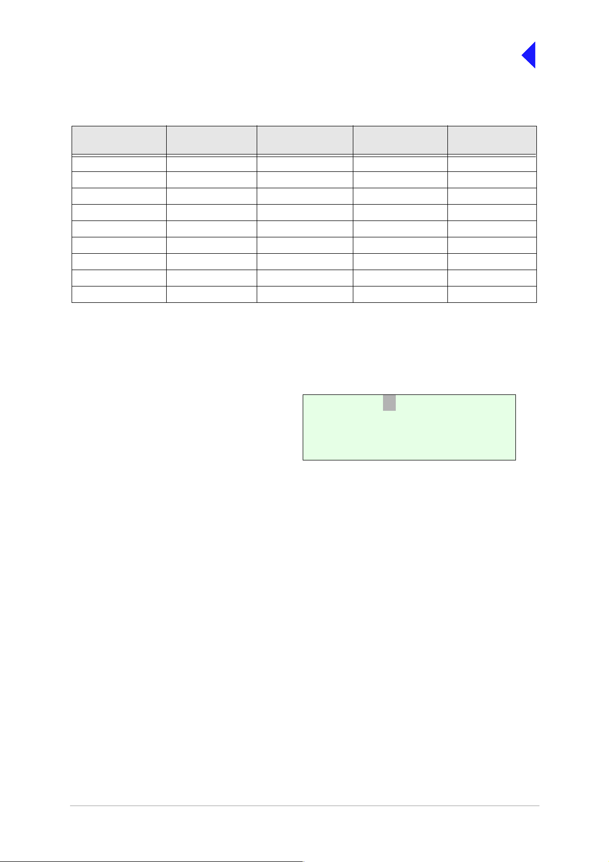
Variants
The T6T VHF Multimode Transmitter is available in the variants as listed in Table 1.
Table 1 Transmitter Variants
Description Part Number Frequency Range Special Applications
50 watt standard frequency
coverage transmitter
50 watt extended frequency
coverage transmitter
50 watt, high stability, standard
frequency coverage transmitter
50 watt, high stability, extended
frequency coverage transmitter
B6350/NB/50 1 18 to 136.975 MHz Supports 2, 3 and 4- offset
carrier operation
B6350/WB/50 1 12 to 155.975 MHz Supports 2, 3 and 4- offset
carrier operation
B6350HS/NB/50 1 18 to 136.975 MHz Supports 5-offset carrier
operation
B6350HS/WB/50 1 12 to 155.975 MHz Supports 5-of fset carrier
operation
Frequency accuracy
All variants except HS Better than 1 ppm.
HS variants Better than 0.3 ppm.
Number of Channels
All variants The transmitter has a multichannel capability. 100 channels can be
stored and recalled.
Power Requirements
The transmitter operates from an ac mains supply, or a dc input supply. When both supplies are
connected, the dc input acts as an automatic backup for the ac mains.
ac input supply The transmitter operates from a 48 to 62 Hz single-phase ac supply
and automatically adjusts to operate from any supply voltage ranging
from 110 Vac to 240 Vac ±10%. The power consumption figures are
given in Table 2.
dc input supply The transmitter operates from a dc input supply between 21.6 and
32 V (measured at the radio’s input). Current loading is given in
Table 2.
T6T 50 W VHF Transmitter Page 2 Specification
Page 5

Back to Transmitt e r
Main Page
Table 2 Power Consumption
Requirement Normal Operation
ac dc
Maximum 500 VA 12 A
Not Transmitting 60 VA 1 A
Dimensions and Weight
The dimensions and weight of the transmitter are:
Width 483 mm (19 inches).
Height 88.9 mm (3.5 inches). The height occupies 2U of equipment cabinet
space.
Depth 430 mm (16.9 inches) measured from front panel to rear panel.
450 mm (17.8 inches) measured from front panel to rear of fan.
Weight 13.5 kg (29.76 pounds).
Environmental
Temperature range The transmitter operates to specification across the temperature
range of -20°C to +55°C.
The transmitter can be stored at temperatures ranging from
-30°C to +70°C without causing any damage.
Humidity The transmitter operates to specification at a relative humidity
between 5% and 90% non-condensing.
Altitude The radios operate to specification up to 15,000 feet. Additionally the
equipment is capable of storage at altitudes up to 50,000 feet without
damage.
Shock and vibration The radios comply with shock and vibration protection MIL-STD-810E,
method 516.4, procedure VI - Bench Handling.
Ventilation The transmitters are cooled by an integral fan, which normally runs at
half speed. At an RF PA temperature of 45°C this is increased to full
speed and at 40°C it reduces to half speed again.
The transmitters also include an additional temperature controlled fan
contained in the power supply.
Warm up time All variants are fully operational to specification within 20 seconds
after switch on except the T6T HS, which is fully operational within 20
seconds but can takes up to 10 minutes to achieve frequency
accuracy for offset carrier.
T6T 50 W VHF Transmitter Page 3 Specification
Page 6

Back to Transmitt e r
Main Page
AM Modes
The transmitter can operate in AM-Voice mode (st andard) and A M -MSK mo de (opt ional). The following
specifications apply to both modes unless stated otherwis e.
Transmitter RF Characteristics
RF Power Outpu t
The RF carrier output power is a djustable in 1 W steps f rom 5 W to 50 W (as an option, the maxim um
selectable power can be limited). Output power is automatically controlled under the following conditions:
Frequency range Variations in power remain within -0 to +1 dB over the operational
frequency range.
Low supply voltage Variations in power remain within ±1 dB for supply voltages between
24 Vdc and 32 Vdc.
High VSWR Loop error can reduce power progressively by up to 3 dB. Variations
in power remain within ±1 dB into a VSWR of up to 2.5:1. At a VSWR
greater than this the output power may be reduced by 10 dB ±1 dB.
High RF PA temperature If the RF PA temperature sensor exceeds 80°C the output power is
reduced by 3 dB ±1 dB. If the RF PA temperature sensor exceeds
90°C the transmitter is de-keyed and automatically re-keyed at 70°C.
Duty Cycle
All variants 100% continuous operation.
Channel Spacing
AM-Voice mode The transmitters are capable of both 25 kHz channel spacing and
8.33 kHz channel spacing.
AM-MSK mode 25 kHz.
Offset Carrier
Non-HS variants (AM-Voice) The non-HS T6T is capable of offsetting the carrier frequency to
provide 2, 3 and 4 carrier offset.
HS variants (AM-Voice) The HS T6T is capable of offsetting the carrier frequency to provide 2,
3, 4 and 5 carrier offset.
AM-MSK mode Offset carrier is not available.
Harmonic Outputs
All variants Second harmonic outputs are less than -36 dBm, third harmonic
outputs are less than -46 dBm and fourth harmonic outputs and above
up to 4 GHz, are less than -56 dBm.
T6T 50 W VHF Transmitter Page 4 Specification
Page 7

Back to Transmitt e r
Main Page
Spurious Outputs
All variants The spurious outputs are less than -46 dBm for modulation depths up
to 90%, measured at greater than 500 kHz from carrier in the
frequency range 9 kHz to 4 GHz. There are no coherent spurious
outputs above the spectral mask at less than 500 kHz.
Intermodulation
All variants Intermodulation products, caused by an interfering signal with the
same power as the transmitter isolated by 30 dB, are at least -40 dBc
at ≥±150 kHz and -50 dBc at ≥±500 kHz.
Transmitter Modulation Characteristics
The transmitter modulation characteristics are as follows:
Mode
AM-Voice AM-Voice mode uses Double Sideband (DSB) Amplitude Modulation
(AM) full carrier; emission designator 6K80A3EJN for 25 kHz
channels and 5K00A3EJ N for 8.33 kHz channels.
AM-MSK AM-MSK mode uses Double Sideband (DSB) Amplitude Mod ulation
(AM) full carrier; emission designator 13K0A2DJN.
Modula tion Depth
All variants The transmitter is capable of modulation depths up to 95%.
Hum and Noise
All variants The hum and noise is more than 45 dB below the signal level for line
input levels <-13 dBm, and more than 50 dB below the signal level for
line input levels ≥-13 dBm, for a carrier modulated by a 1 kHz signal
with a modulation depth of 90%.
Frequency Response
25 kHz channel spacing AM-Voice and AM-MSK: The variation in frequency response with
reference to a 1 kHz signal is within +0.5 dB and -1.5 dB across the
frequency range 300 to 3400 Hz. The response is also less than -20
dB at 100 Hz and below, and less than -30 dB at 4 kHz and above.
8.33 kHz channel spacing AM-Voice only: The variation in frequency response with reference to
a 1 kHz signal is within +0.5 dB and -1.5 dB across the frequency
range 350 Hz to 2500 Hz. The response is also less than -10 dB at 100
Hz and below, and less than -30 dB at 3200 Hz and above.
Distortion
25 kHz channel spacing The total harmonic distortion is less than 5% due to signals with a
modulation depth of 90%, within the frequency range 300 Hz to
3400 Hz.
8.33 kHz channel spacing AM-Voice only: The total harmonic distortion is less than 5% due to
signals with a modulation depth of 90%, within the frequency range
350 Hz to 2500 Hz.
T6T 50 W VHF Transmitter Page 5 Specification
Page 8

Back to Transmitt e r
Main Page
Residual FM
All variants For a test signal of 1 kHz set at 80% modulation depth applied to the
line input of the transmitter, the unwanted peak frequency modulation
does not exceed ±500 Hz.
VOGAD
AM-Voice The VOGAD has an operational range of 30 dB. The VOGAD can be
disabled.
AM-MSK The VOGAD is disabled.
Mute
AM-Voice The mute level is set at 15 dB below the average speech line level
setting. The mute can be disabled.
AM-MSK The mute is disabled.
Differential Group Delay
AM-MSK There is less than 60 µs differential group delay for signals in the
range 1200 to 2400 Hz.
Transmitter Control
Transmitter control characteristics are as follows:
Audio Inputs
All variants Voice can be connected to the transmitter via the front panel
microphone connector. Voice can also be connect ed via the line
inputs. Line level setting from -30 to +10 dBm.
PTT Tim e Out
All variants The time out period is adjustable from 2 to 510 seconds in 2 second
steps or can be disabled.
T6T 50 W VHF Transmitter Page 6 Specification
Page 9

Back to Transmitt e r
Main Page
Mode 2
This section gives the transmitter’s specification applicable to Mode 2 operation. Mode 2 parameters are
identical to AM-Voice mode parameters with the following exceptions:
RF Power Rise Time
All models T he transmitte r produces more than 90% of full power output within
the first 2 symbols of the power stabilization segment, which is the first
segment of the training sequence and consists of 4 symbols each
representin g 000.
RF Power Decay Time
All models The output power decays by more than 20 dB within 2.5 symbols of
the middle of the final symbol.
Channel Spacing
All models 2 5 kHz ch annel spacing only.
Transmitter Modulation Characteristics
Mode
All models Mode 2 uses Carrier Sense Multiple Access (CSMA) differentially
encoded 8-phase shift keying (D8PSK), using a raised cosine filter
with α=0.6 (nominal value), emission designator 14K0G1DE.
Information is differentially encoded with 3 bits per symbol transmitted
as changes in phase rather than absolute phase. The data stream is
divided into groups of 3 consecutive data bits, least significant bit first.
Zeros are padded to the end of transmissions if needed for the final
channel symbol.
Modulation Rate
All models The symbol rate is 10,500 symbols/second (±0.005%), resulting in a
nominal bit rate of 31,500 bits/s.
RMS Phase Error
All models T he RM S phase error is less than 3°. The error vector magnitude is
less than 6%.
Phase Acceleration
All models The total frequency change during the transmission of the unique word
is less than 10 Hz. After this, the phase acceleration is less than
500 Hz/s.
T6T 50 W VHF Transmitter Page 7 Specification
Page 10

Back to Transmitt e r
Main Page
Mode 3
This section gives the transmitter’s specification applicable to Mode 3 operation. Mode 3 parameters are
identical to AM-Voice mode parameters with the following exceptions:
RF Power Rise Time
All models T he transmitte r produces more than 90% of full power output within
the first 2 symbols of the power stabilization segment, which is the first
segment of the training sequence and consists of 4 symbols each
representin g 000.
RF Power Decay Time
All models The output power decays by more than 20 dB within 2.5 symbols of
the middle of the final symbol.
Channel Spacing
All models 2 5 kHz ch annel spacing only.
Transmitter Modulation Characteristics
Mode
All models Mode 3 uses Time Division Multiple Access (TDMA) differentially
encoded 8-phase shift keying (D8PSK), using a raised cosine filter
with α=0.6 (nominal value), emission designator 14K0G7WET.
Information is differentially encoded with 3 bits per symbol transmitted
as changes in phase rather than absolute phase. The data stream is
divided into groups of 3 consecutive data bits, least significant bit first.
Zeros are padded to the end of transmissions if needed for the final
channel symbol.
Modulation Rate
All models The symbol rate is 10,500 symbols/second (±0.005%), resulting in a
nominal bit rate of 31,500 bits/s.
RMS Phase Error
All models T he RM S phase error is less than 3°. The error vector magnitude is
less than 6%.
Phase Acceleration
All models The total frequency change during the transmission of the unique word
is less than 10 Hz. After this, the phase acceleration is less than
500 Hz/s.
End of document
T6T 50 W VHF Transmitter Page 8 Specification
Page 11

Operation
Back to Transmitter
Main Page
This document describes the controls, indicators, setting up and operating instructions
applicable to the T6T VHF Multimode Transmitter.
Page 12

Back to Transmitter
Main Page
Controls , Indicators and Front Panel Connectors
This part details the purpose of all controls and indicators of the T6T transmitters.
Front Panel
The front panel’ s controls, indicators an d connectors are shown below and detailed in the following
paragraphs.
Scroll/Select SwitchLCD
ALARM
TRANSMIT
READY
STANDBY
F r e q 1 1 8 .0 0 0 M H z
C h 1 0 0 + 7 . 3 k H z
M o d e A M V o i c e 1
P w r
SCROLL/
SELECT
REFERENCE
MICROPHONE/
DIAGNOSTICS
Scroll/Select Switch and LCD
The Scroll/Select switch is used in conjunction with the LCD to select most of the transmitter's operational
settings. Use of the switch and LCD is fully detail ed in this section appl icable to th e particular operating
mode. During normal operation, the LCD shows the operating frequency, the channel number (if the
channel store f acility is used), the carrier offset (if used), and dis plays a graphical representatio n of
instantaneous peak power.
The example LCD sc reen above shows the t ransmitter operating on 11 8.000 MHz; the frequen cy has
been preset as channel 100 and offset at +7.3 kHz.
Ready Indicator
A green indicator that lights when the transmitter is ready for use and no BIT faults have been detected.
Transmit Indicator
An amber indicator that lights when the transmit circuit is keyed and producing output power.
Alarm Indicator
A red indicator that either flashes, or lights, when a BIT fault has been det ected. BIT indications are
classified as either Alarms or Alerts.
If an ‘alert’ condition is detected, the Alarm ind icator flashes, the Ready indicator remains lit, and the
transmitter remains operational. A BIT ‘alert’ is indicated if:
❑ If the transmitter RF output powe r has redu ced from its setting by m ore than 1 dB but not more
than 3 dB.
❑ If the supply volts falls below a pre-defined level.
Any other BIT condition results in an alarm. When detected, the Alarm indicator lights and the Ready
indicator becomes unlit; the transmitter cannot be used.
T6T VHF 50 W Transmitter Page 2 Operation
Page 13
Back to Transmitter
Main Page
Standby Indicator
A red indicator that lights when the tra nsmitter is in stan dby m ode. When in standby mode, m ost of the
radio's circuits are inactive, the front panel LCD is blanked, and the transmitter cannot be keyed.
Standby mode is selected and deselected using the front panel Scroll/Select switch and LCD, by initiating
an instruction through a MARC system, through a T6 controller or through the VFP. For details of front
panel selection and deselection see page 13.
Reference Connector
An SMB jack socket that allows a frequency counter to monitor the transmitter's reference frequency.
This connector is used only for maintena nce purposes. The instruction s for checking and adjusting the
reference frequency are given in the Maintenance section.
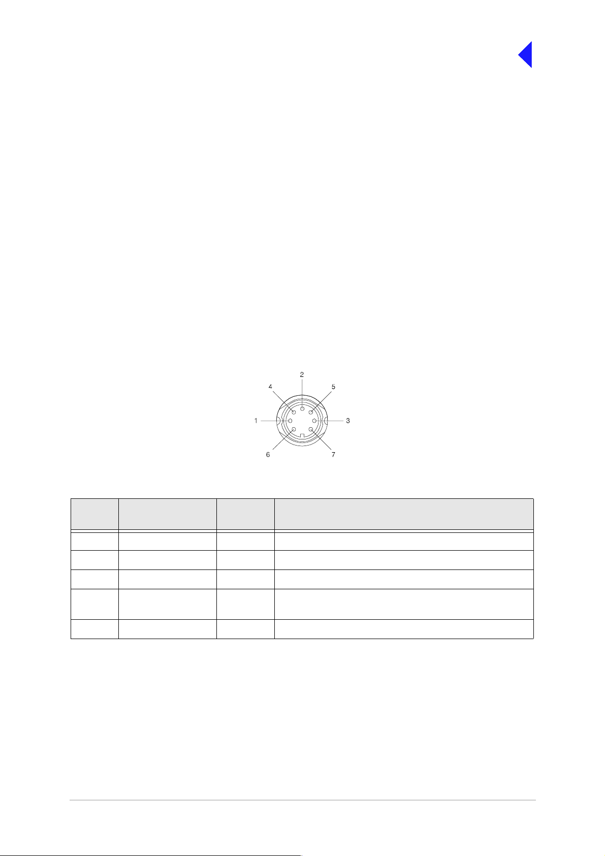
Microp ho ne / D i agnostics Connector
A dual purpose c onnect or t hat all ows ei ther a m icrophone, or a PC, t o be connected to th e t ransmi tter.
The connector is a 7-pin self-locking DIN socket; the pin-out is shown in Table 1.
A microphone i s fitted to t his connector to enable the t rans mitter to be operated in AM local mo de. The
connections are detailed in Table 1. A PC can also be connected to allow the VFP to be displayed. Using
the VFP is detailed in the Mai ntenance section. The PC connections at the transmitter are s hown in
Table 2 on page 4.
Viewed from front
Table 1 Microphone/Diagnostics Connector - Audio Connections
Pin
Number
1 Microphone ground - 0 V.
3 Microphone PTT Input 0 V to PTT.
5 Sidetone Output 0 to 3 V pk-pk.
6 Micro phone input Input 2 to 35 mV rms on Passive setting and 8 to 140 mV rms on
7 Ground - 0 V.
Signal Input or
Output
Description
Active setting to remain in VOGAD range.
T6T VHF 50 W Transmitter Page 3 Operation
Page 14
Back to Transmitter
Main Page
Table 2 Microphone/Diagnostics Connector - PC Connections
Pin
Number
2 Transmit data Ou tput RS232, 115200 baud, 8 data bits, 1 stop bit, no parity, no
4 Receiv e data Input RS232, 1 15200 baud, 8 data bits, 1 stop bit, no parit y, no
7 Ground - 0 V.
Signal Input or
Output
Description
handshaking.
handshaking.
Rear Panel Power Switch
The rear panel's power switch is a 2-way rocker switch used to select between power on, and standby.
WARNING
When the POWER SWITCH is set to the Standby position, dangerous voltages are still
present in the transmitter's internal power supply circuitry. To ensure safe working, the
transmitter must be isolated from the ac and dc input supplies.
Dangerous Voltages
= Standby= On
T6T VHF 50 W Transmitter Page 4 Operation
Page 15

Back to Transmitter
Main Page
Setting Up and Operation
Introduction
Setting up the transmitter involves sele cting various parameters using the Virtual Front Panel (VFP),
through a Multi-Access Remote Control (MARC) system, from a T6 controller, or from the transmitter’s
front panel. The transmitter can be configured for remote or local use.
Table 9 on page 30 details the functions and parameters that can be set from all these sources.
The rest of this document details how to configure the transmitter from the front panel, and how to operate
the radio in local mode.
Selecting most of the transmitter's operational settings is carried out using the front panel Scroll/Select
switch and the LCD (see the illustration below). No attempt to set up the transmitter should be made until
the transmitter has been installed as per the installation procedures given in the Installation section.
Normal Operation
During normal operation, the LCD displays the Main screen. This screen shows the operating frequency,
the channel number ( if the channel store fac ility is used), the carrier offset (if used), and displays a
graphical representation of output power when the transmitter is keyed. If the transmitter has been set to
Standby mode, which is shown by the front panel Standby indicator being lit, the LCD is blanked.
Scroll/Select SwitchLCD
ALARM
TRANSMIT
READY
STANDBY
F r e q 1 1 8 .0 0 0 M H z
C h 1 0 0 + 7 . 3 k H z
M o d e A M V o i c e 1
P w r
SCROLL/
SELECT
REFERENCE
MICROPHONE/
DIAGNOSTICS
Using the Scroll/Select Switch
The Scroll/Select switch (ref erred to throughout this section as the ‘Switch’) is used to l eave the Main
screen and display the Control screen (see page 8). Further use of the Switch displays various selection
menus and allows the required pa rameters to be set. The switch has three actions: it can be turned
clockwise, anti-clockwise, or momentarily pushed in.
T6T VHF 50 W Transmitter Page 5 Operation
Page 16

Back to Transmitter
Main Page
Screen Protocol
The following protocol is applicable to all screens described in this document.
Main Screen During normal operation, the Main screen (an example of which is shown below
whilst the transmitter is transmitting) is displayed.
F r e q 1 1 8 . 0 0 0 M H z
C h 1 0 0 + 7 . 3 k H z
M o d e A M V o i c e
P w r I I I I I I I I I I
Switch Refers to the front panel Scroll/Select switch. The switch is turned clockwise to scroll
through fields from left to right, and from top to bottom. The switch is turned
anti-clockwise to scroll through fields from right to left, and from bottom to top. The
switch is pressed to make a selection.
Time out If during any setting up procedure the Scroll/Select switch is not operated for
30 seconds, the display returns to the Main screen. If editing any parameter has not
been completed, the transmitter stays on the original setting.
>> Indicates more fields are available other than those currently displayed. To access
those fields, turn the switch clockwise through the last displayed field.
<< Indicates more fields are available other than those currently displayed. To access
those fields, turn the switch anti-clockwise through the first displayed field.
Back When Back is selected, you are returned to the previous menu.
Exit When Exit is selected, you are returned to the Main screen.
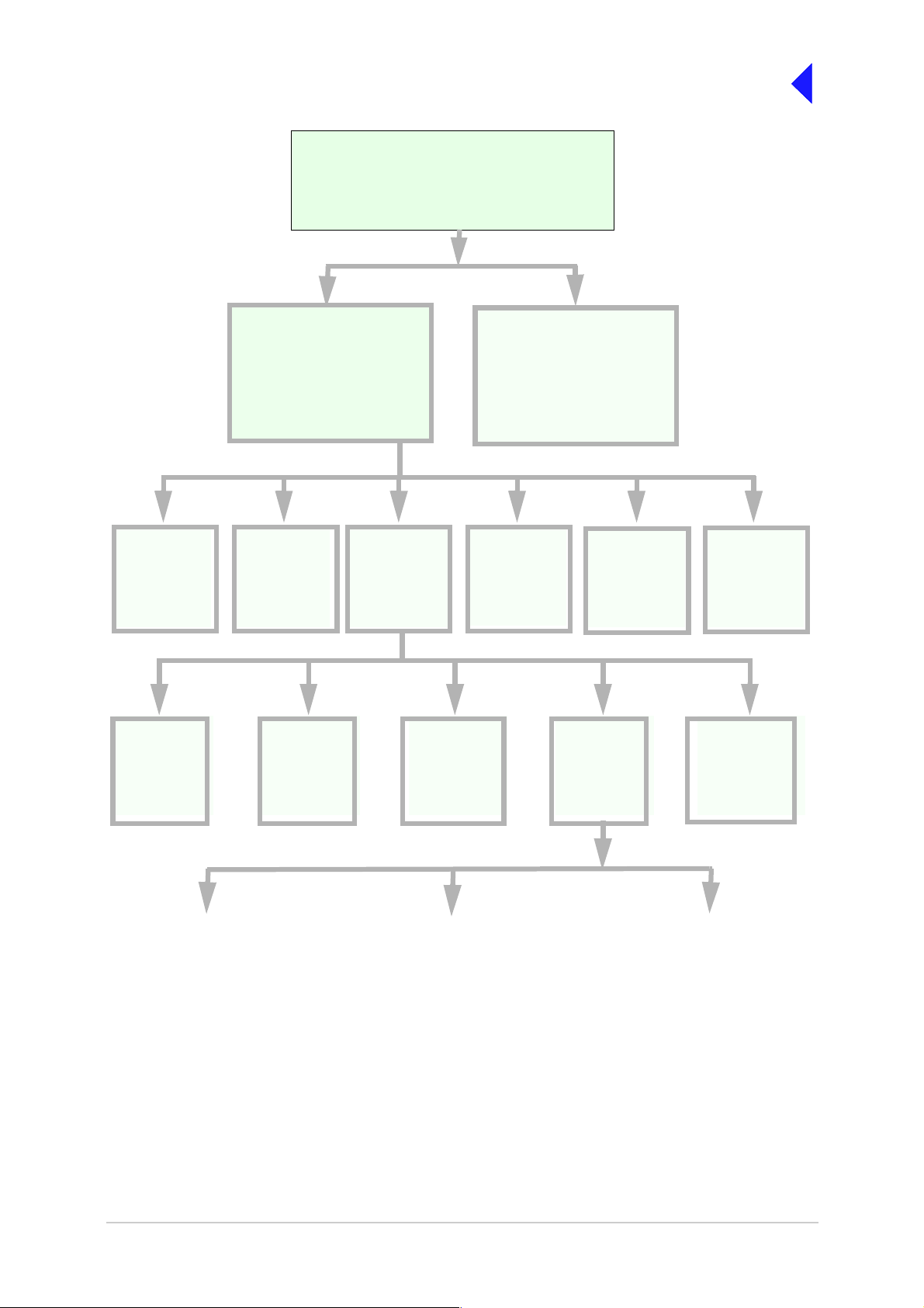
Menu System
The front panel control of the radio is implemented through a hierarchical menu system as shown on the
following page.
T6T VHF 50 W Transmitter Page 6 Operation
Page 17
Back to Transmitter
Main Page
F r e q 1 1 8 . 0 0 0 M H z
C h 1 0 0
M o d e A M V o i c e
P w r I I I I I I I I I I
Main Screen
(Example)
Displayed during normal
transmitt er operation
Frequency
Set the
transmitter
operating
frequency
Backlight
Adjust the
display’s
backlight
Control Screen
Configure the transmitter
operating par ameters , access
the BIT facility or view the
software configuration
Channel
Set or reca ll up
to 100 preset
frequency
channels
.
Settings
Set the
transmitter
operational
settings
Ref Freq
Adjust the
transmitter
reference
frequency
Initiate a BIT
test and view
Band Edges
Set up the
transmitter
band edges
Menu Lock Screen
(see page 8)
BIT
results
S/W Config
transmitter
configuration
Mode and
Mode
Settings
Select Mode
View the
software
Standby
Enter or Exit
standby mode
Polarities
Set the active
polarity for
certain hardwire
connections
AM-Voice Mode
Settings
(see page 16)
AM-MSK Mode
Settings
(see page 18)
Digital Modes
(see page 19)
Menu System
T6T VHF 50 W Transmitter Page 7 Operation
Page 18

Back to Transmitter
Main Page
Menu Lock S creen
A security facility available only from the VFP allows the transmitter's front panel to be ‘locked’. When
this facility is active, no operational settings can be made from the front panel until an ‘unlock’ command
is sent from the VFP.
The following screen is displayed when ‘lock’ is active, and the front panel switch is pressed.
S E C U R I T Y M E S S A G E
F r o n t P a n e l
L o c k e d
O K
To exit the system lock screen:
❑ Select OK, then press the switch. You are returned to the Main screen.
or,
❑ Wait for the 30 second time-out to expire. You are returned to the Main screen.
Control Screen
The Control screen is entered from the Main screen by pressing the switch. T he following screen is
displayed:
Change the transmitter’s operating frequency.
Store or recall preset channel frequencies.
Select operating mode and m ode settings.
Initiate a BIT test and view results.
View software configuration.
Enter or exit standby mode.
F r e q u e n c y
C h a n n e l
S e t t i n g s
E x i t > >
B I T
S / W C o n f i g
S t a n d b y
E x i t < <
T6T VHF 50 W Transmitter Page 8 Operation
Page 19

Back to Transmitter
Main Page
Notes for Setting Up the Transmitter
The following notes should be read before setting up the transmitter. They advise on the special
frequency display when using 8.33 kHz channel spacing, a nd g ive guidance on the optimum li ne level
settings. Note that for operation in the United States of America, this equipment is certified only for
operation using 25 kHz channel spacing.
Front Panel Display for 25 kHz and 8.33 kHz Channel Spacing
When setting the opera ting frequency of the transmitter and 8 .33 kHz channel spac ing is required, the
displayed frequency differs from the actual channel frequency. Table 3 shows the pattern used for
25 kHz and 8.33 kHz spaced channel frequencies from 118.000 MHz to 118.141 MHz. The pattern is the
same for any frequency within the transmitter's frequency range. The display conforms to ICAO
convention for 8.33 kHz operation.
Table 3 25 kHz and 8.33 kHz Channel Spacing Displays
Actual Frequency
(to 4 decimal places)
1 18.0000 MHz
1 18.0000 MHz
1 18.0083 MHz
1 18.0166 MHz
1 18.0250 MHz
1 18.0250 MHz
1 18.0333 MHz
1 18.0416 MHz
1 18.0500 MHz
1 18.0500 MHz
1 18.0583 MHz
1 18.0666 MHz
1 18.0750 MHz
1 18.0750 MHz
1 18.0833 MHz
1 18.0916 MHz
1 18.1000 MHz
1 18.1000 MHz
1 18.1083 MHz
1 18.1166 MHz
Channel Spacing Displayed Frequency
25 kHz
8.33 kHz
8.33 kHz
8.33 kHz
25 kHz
8.33 kHz
8.33 kHz
8.33 kHz
25 kHz
8.33 kHz
8.33 kHz
8.33 kHz
25 kHz
8.33 kHz
8.33 kHz
8.33 kHz
25 kHz
8.33 kHz
8.33 kHz
8.33 kHz
at Transm itter's Front Panel
118.000 MHz
118.005 MHz
118.010 MHz
118.015 MHz
118.025 MHz
118.030 MHz
118.035 MHz
118.040 MHz
118.050 MHz
118.055 MHz
118.060 MHz
118.065 MHz
118.075 MHz
118.080 MHz
118.085 MHz
118.090 MHz
118.100 MHz
118.105 MHz
1 18.110 MHz
1 18.115 MHz
1 18.1250 MHz
1 18.1250 MHz
1 18.1333 MHz
1 18.1416 MHz
25 kHz
8.33 kHz
8.33 kHz
8.33 kHz
118.125 MHz
118.130 MHz
118.135 MHz
118.140 MHz
Line Level Settings
The input line level setting displayed on the front panel is equivalent to the a vera ge speec h le vel with a
peak-to-average ratio of 13 dB. This corresponds to the level specified for the lines.
When testing the transmitter using a sine wave, the line input level should be set to 10 dB above the line
level setting. The VOG AD and mute t hresholds are pre-set at 10 dB and 15 dB respectively below the
line level setting.
Table 4 shows the relationship between the input line level, VOGAD threshold and mute threshold.
T6T VHF 50 W Transmitter Page 9 Operation
Page 20
Back to Transmitter
Main Page
Table 4 Relationship Between Line Level, VOGAD Threshold and Mute Threshold
Line Level Setting
(dBm)
+10 +10 +20 0 -5
+5 +5 +15 -5 -10
00+10-10-15
-5 -5 +5 -15 -20
-10 -10 0 -20 -25
-15 -15 -5 -25 -30
-20 -20 -10 -30 -35
-25 -25 -15 -35 -40
-30 -30 -20 -40 -45
Average Speech
Level (dBm)
Sine Wave Level
(dBm)
VOGAD Threshold
(dBm)
Mute Threshold
(dBm)
Changing the Transmitter’s Operating Frequency
The transmitter’s frequency can be changed in two ways: either from the frequency screen, or by
recalling a preset channel. This procedure details using the Frequency screen.
(1) From the Control screen, select
frequency to display the Frequency
screen.
F r e q 1 1 8 . 0 0 0 M H z
(2) Turn the switch to highlight the digit to
be changed, then press the switch.
(3) Turn the switch until the required digit
is shown, then press th e swit ch.
(4) Repeat until the required freq uency is
shown, then highlight OK and press the
switch.
(5) Only frequencies that fa ll between the
band edge settings can be selected.
C a n c e l O K
T6T VHF 50 W Transmitter Page 10 Operation
Page 21

To Store and Recall Frequency Channels
Up to 100 frequency channels can be stored in the transmitter.
To store a Channel Frequency
Back to Transmitter
Main Page
(1) From the Control screen, select
Channel to display the Channel
screen. Highlight Channel, press the
switch and then turn it until the required
channel number is displayed; press the
switch.
(2) Highlight the MHz frequency value
(see Example 2) press the switch and
then turn it until the required MHz value
is shown. Press the switch.
(3) Highlight the kHz frequency value (see
Example 3), press the swi tch and then
turn it until the required kHz value is
shown. Press the switch.
(4) Highlight Store and press the switch.
The new frequency is now stored in the
selected channel number.
To recall a Stored Frequency Channel
(1) From the Control screen, select
Channel to display the Channel
screen.
(2) To make the transmitter operate on
any preset channel frequency,
highlight Channel and press the switch.
Turn the switch until the required
channel number/frequency is
displayed, then press the switch.
(3) Turn the switch to highlight Recall, then
press the switch. Exit the screen. The
transmitter now operates on the
recalled channel frequency.
C h 1 0 0
F r e q 1 2 1 . 5 0 0 M H z
R e c a l l
B a c k E x i t
Channel Screen - Example 1
C h 1 0 0
F r e q 1 1 8 . 0 0 0 M H z
S t o r e
B a c k E x i t
Channel Screen - Example 2
C h 1 0 0
F r e q 1 1 8 . 0 0 0 M H z
O u t s i d e B a n d E d g e
B a c k E x i t
Channel Screen - Example 3
C h 1 0 0
F r e q 1 1 8 . 0 0 0 M H z
I nn v a l i d f o r M o d e
B a c k E x i t
Channel Screen - Example 4
Notes:
If a frequency outside the band edge limits is
entered, a message (see Channel Screen Example 3) is displayed.
If a frequency not valid for the mode of
operation is entered, a message (see Ch annel
Screen - Example 4) is displayed.
T6T VHF 50 W Transmitter Page 11 Operation
Page 22

Back to Transmitter
Main Page
To Initiate a BIT Test
Use the following procedure to initiate an interruptive BIT test from the transmitter's front panel. A BIT
test cannot be initiated while the transmitter is keyed. After a BIT test has been run, the BIT screen is
displayed (see AM-Voice and AM -MSK BIT Screen on page 24). An i nterruptive BIT tes t cannot be
initiated in Mode 2 or Mode 3.
During an interruptive BIT te st, the t ransm itter radiates m odulated carrier waves at the s et power.
Users should therefore obtain the necessary authority before initiating a test.
If the test is to be carried out with the antenna disconnected, ensure a load is fitted to the
transmitter's antenna connector.
In order to test the line input stages, an internally generated 1 kHz tone is injected into the line input
circuit. Any other audio present on the line input will cause the test to be inaccurate. Therefore the
transmitter must not be keyed during the test.
(1) From the Main screen, press the switch to display the Control screen. Turn the switch until BIT
is highlighted. Press the switch.
B I T
S / W C o n f i g
S t a n d b y
E x i t < <
(2) Ensure the BIT me nu is displayed. Turn the switch u ntil BIT Initiate is highlighted. Press the
switch.
B I T I n i t i a t e
E T I 0 0 0 0 0 : 0 0 h r s
A C S u p p l y O N
E x i t > >
(3) During the test, which takes approximately two seconds, the Testing screen is displayed.
T e s t i n g
P l e a s e W a i t
T6T VHF 50 W Transmitter Page 12 Operation
Page 23

Back to Transmitter
Main Page
(4) On completion, and if the interruptive test was initiated from the front panel, one of the following
screens will be shown.
T e s t S t a t u s
P A S S
O K
(5) Selecting OK takes the user back to the BIT screen.
T e s t S t a t u s
F A I L
O K
(6) Selecting OK takes the user back to the BIT screen. The user can then scroll through the screen
to check out transmitter parameters for failure.
Standby Mode
Standby mode is a pow er saving feature that can be used for non-operat ional transmitters. When in
standby mode, most of the transmitter's circuits are inactive, the LCD is blanked, and the transmitter
cannot be keyed. To put the transmitter into standby mode, use the following procedure.
When the transmitter is in Standby mode, the red front panel Standby indicator is lit.
To Enter Standby Mode
(1) From the Control screen select
Standby.
(2) At the Standby screen, select Yes.
(3) Check that the display blanks and
the front panel Standby indicator is
lit.
To Exit Standby Mode
(1) Press the Switch.
(2) Select Yes.
(3) Check that the Main screen is
displayed and that the front panel
Standby indicator is unlit.
E n t e r S t a n d b y ?
Y e s N o
E x i t S t a n d b y ?
Y e s N o
T6T VHF 50 W Transmitter Page 13 Operation
Page 24

Back to Transmitter
Main Page
Settings
Operational settings for the T6T VHF transmitter are configured at the front panel, through the VFP, and
through an associated MARC system (or compatible control system). Some settings can also be made
remotely via a T6 controller. The Settings screen is entered from the Control screen.
The settings that can be selected at the front panel Settings screen are:
❑ Mode - either AM-Voice, AM-MSK, Mode 2 or Mode 3
❑ Mode Settings - allows the selected mode parameters to be set
❑ Polarities
❑ Band edges
❑ Backlight
❑ Reference frequency.
Note that the mode selection, ref erence frequency and backlight are set from this screen. W hen mode
settings, polarities and band edges are selected the user is taken to other screens.
M o d e A M V o i c e
M o d e S e t t i n g s
P o l a r i t i e s
E x i t > >
B a n d E d g e s
R e f F r e q 5 0 . 0 %
B a c k l i g h t 0 3 0 s
E x i t < < > >
B a c k
E x i t
Notes:
Select between AM-Voice, AM-MSK, Mod e 2 or Mode 3.
Select to take you to the mode specific Settings menu.
Select to take you to the Polarities menu.
Set the transmitter’s frequency band edges.
Align the transmitter’s reference frequency (Note 1).
Adjust the LCD’s backlight time out (Note 2).
1.Setting the transmitter’s reference frequency is a maintenance operation. The current value should
not be reset unless the correct test equipment is connected. See the Maintenance section.
2.The LCD’s backlight can be s et for permanent ly on, off, or timed t o stay on for a pe riod between
15 and 120 seconds.
General and mode specific settings, showing default values, are referenced in Table 5 on page 15. Click
on any required parameter by page number for further references.
T6T VHF 50 W Transmitter Page 14 Operation
Page 25

Table 5 Opera tio nal Settings fr om t he Front Panel
Back to Transmitter
Main Page
Parameter Mode Adjustment Range Factory Default Setting Further
Menu lock screen All Locked or unlocked Unlocked page 8
Enter standby
mode
Exit standby mode All Yes or No - page 13
Set mode of
operation
Set polarities AM-voice,
Band edges All 118.000 to 136.975 MHz
LCD Backlight All 15 to 120 s, On or Off 30 s page 14
RF power All 5 to 50 W 50 W page 16
Audio line in level AM-voice,
Inhibit AM-voice,
PTT (key) AM -voice,
Tx time out AM-voice,
Modulation depth AM-voice,
Mute AM-voice O n or Off On page 16
VOGAD AM-voice O n or Off On page 16
Antenna C/O delay AM-voice
All Yes or No -
All AM-voice, AM-MSK, Mode
2 or Mode 3
STD or INV STD page 20
AM-MSK
or
1 12.000 to 155.975 MHz
-30 to +10 dBm -13 dBm page 16 and
AM-MSK
On or Off Off page 16 and
AM-MSK
On (key), Off (de-key) Off page 16 and
AM-MSK
2 to 510 s or Off 180 s page 16 and
AM-MSK
5 to 95% 85% page 16 and
AM-MSK
On or Off On
AM-voice page 14
118.000 and 136.975 MHz
or
112.000 and 155.975 MHz
Reference
page 13
page 28
page 18
page 18
page 18
page 18
page 18
page 16
AM-MSK
Offset AM-voice 0, ±2.5, ±5, ±7.3, ±7.5 kHz
(additionall y, ±4 and
±8 kHz on HS models)
Ste p AM-voice 8.33 kHz, 25 kHz or both 25 kHz page 17
Mic AM-voice Active or Passive Passive page 17
Key priority AM-voice,
AM-MSK
Local PTT A M-voice,
AM-MSK
Remote PTT AM-voice,
AM-MSK
Remote phantom
PTT
T6T VHF 50 W Transmitter Page 15 Operation
AM-voice,
AM-MSK
Local-Remote or
Remote-Local
Enabled or Disabled Enabled page 17 and
Enabled or Disabled Enabled page 17 and
Enabled or Disabled Enabled page 17 and
Off
0 (No offset) page 17
Local-Remote page 17 and
page 18
page 18
page 18
page 18
page 18
Page 26

Back to Transmitter
Main Page
AM Voice Settings Procedure
During this procedure, the following parameters, applicable to AM-voice operation, can be set:
❑ RF power output
❑ Audio line input level
❑ Inhibit
❑ PTT on (key) or off (de-key)
❑ Transmitter time out
❑ Modulation depth
❑ Mute (on or off)
❑ VOGAD (on or off)
❑ Antenna c/o delay (on or off)
❑ Offset
❑ Step
❑ Mic
❑ Key priority ( local or remote)
❑ Enable or disable local PTT
❑ Enable or disable remote PTT
❑ Enable or disable remote phantom PTT.
AM Voice Mode Settings Screen
The AM-voice mode setting screen is accessed from the Settings screen. Use the Scroll/Select switch to
select the parameter, then enter the required setting(s).
Adjustments
P o w e r 5 0 W
L i n e I n - 1 3 d B m
I n h i b i t O F F
E x i t > >
P T T O F F
T X T i m e o u t 1 8 0 s
M o d D e p t h 8 5 %
E x i t < < > >
RF power between 5 W to 50 W.
Audio line in level between -30 to +10 dBm.
On or Off.
On (key), Off (de-key).
2 to 510 s.
5 to 95%.
M u t e O N
V O G A D O N
A n t C / O D e l O N
On or Off.
On or Off.
On or Off.
E x i t < < > >
T6T VHF 50 W Transmitter Page 16 Operation
Page 27

Adjustments
Back to Transmitter
Main Page
O f f s e t 0 . 0 k H z
S t e p 2 5 k H z
M i c P A S S I V E
E x i t < < > >
K e y P r i o r i t y L - R
L o c a l P T T E N
R e m o t e P T T E N
E x i t < < > >
R e m P h a n P T T E N
B a c k
E x i t < <
0, ±2.5, ±5, ±7.3, ±7.5 , (or ±4, ±8 HS only) kHz.
25 kHz, 8.33 kHz or both.
Active or Passiv e.
Local-remote or Remote-local.
Enabled or Disabled.
Enabled or Disabled.
Enabled or Disabled.
Return to screen.
T6T VHF 50 W Transmitter Page 17 Operation
Page 28

Back to Transmitter
Main Page
AM-MSK Mode Se ttings Proced ure
During this procedure, the following parameters, applicable to AM MSK operation, can be set:
❑ RF power output
❑ Audio line input level
❑ Inhibit
❑ PTT on (key) or off (de-key)
❑ Transmitter time out
❑ Modulation depth
❑ Antenna c/o delay (on or off)
❑ Key priority ( local or remote)
❑ Enable or disable remote PTT
❑ Enable or disable remote phantom PTT.
AM-MSK Mode Sett ings Screens
The AM-MSK mode setting screen is accessed from the Settings screen. Use the Scroll/Select switch to
select the parameter, then enter the required setting(s).
P o w e r 5 0 W
L i n e I n - 1 3 d B m
I n h i b i t O F F
E x i t > >
P T T O F F
T X T i m e o u t 1 8 0 s
M o d D e p t h 8 5 %
E x i t < < > >
A n t C / O D e l O N
K e y P r i o r i t y L - R
L o c a l P T T E N
E x i t < < > >
Adjustments
RF power between 5 W to 50 W.
Audio line in level between -30 to +10 dBm.
On or Off.
On (key), Off (de-key).
2 to 510 s.
5 to 95%.
On or Off.
Local-remote or Remote-local.
Enabled or Disabled.
R e m o t e P T T E N
R e m P h a n P T T E N
Enabled or Disabled.
Enabled or Disabled.
B a c k
E x i t < <
T6T VHF 50 W Transmitter Page 18 Operation
Page 29

Mode 2 Settings Screen
This is an advisory screen. Pressing OK returns the user to the Main screen.
M o d e 2 p a r a m e t e r s
a r e s e t v i a t h e
H L D C i n t e r f a c e
O K
Mode 3 Settings Screen
This is an advisory screen. Pressing OK returns the user to the Main screen.
M o d e 3 p a r a m e t e r s
a r e s e t v i a t h e
T 1 / E 1 i n t e r f a c e
O K
Back to Transmitter
Main Page
T6T VHF 50 W Transmitter Page 19 Operation
Page 30

Back to Transmitter
Main Page
Polarities Screens AM-Voice and AM-MSK
A number of remote indication and control signals can be hard-wire connected to the transmitter. These
signals include a transmitter ready indication, a PTT control signal, a phantom PTT control signal, a PTT
out indication, a transmitter inhibit control signal, a BIT test initiation control signal, an external VSWR
fault indication and antenna C/O. The following paragraphs detail the signals applicable to the
operational mode of the transmitter.
The Polarities screen is accessed from the Settings screen.
AM-Voice and AM-MSK Polarity Settings
R e a d y O u t S T D
E - B I T I n S T D
I n h i b i t I n S T D
E x i t > >
B I T S t a r t I n S T D
P T T R e f + 1 4 V
P T T I n S T D
E x i t > >
P h a n P T T I n S T D
P T T O u t S T D
F a s t P T T O u t S T D
E x i t < < > >
E x t V S W R I n S T D
A n t C / O O u t S T D
B a c k
E x i t < <
Each of ten polarity settings applicable to
AM-voice and AM-M SK can be set to the default
STD (standard) setting or INV (inverted).
The signal conn ections are shown in T able 6 on
page 21 along with the conditions when STD or
INV is selected.
The settings for the PTT Reference voltage are
also shown in Table 6.
T6T VHF 50 W Transmitter Page 20 Operation
Page 31

Back to Transmitter
Main Page
Table 6 AM-Voice and AM-MSK Polarity Settings
Signal Connector Polarity set to STD Polarity set to INV
Ready Out Facilit ies, pin 13 An open collector grounded
output when the radio is ready
to transmit and no BIT faults
are detected.
E-BIT In Facili ties, pin 2 TTL input. 0 V indicates an
extern a l fault .
Inhibit In Facilities, pin 10 TTL input. 0 V inhibits
transmitter operation.
BIT Start In Facilities, pin 11 TTL input. 0 V initiates an
interruptive BIT test.
PTT In MARC, pin 4
MARC Audio, pin 6
Phantom PTT In MARC or
MARC Audio, pin 2
Active when input differs from
reference by more than ±10 V.
Inactive wh en input dif fers from
reference by less than ±1 V.
Maximum input level ±60 V
with respec t to re ference . Input
will dra w no mo r e than 6 mA ,
requires at least 1 mA to
operate.
Active when input differs from
reference by more than ±10 V.
Inactive wh en input dif fers from
reference by less than ±1 V.
Maximum input level ±60 V
with respec t to re ference . Input
will dra w no mo r e than 6 mA ,
requires at least 1 mA to
operate.
An open collector high
impedance output when t he
radio is ready to transmit and
no BIT faults are detected.
TTL input. 5 V indicates an
external fault.
TTL input. 5 V inhibits
transmitte r operation.
TTL input. 5 V initiates an
interruptive BIT test.
Active when input dif fers from
reference by less than ±1 V.
Inactive when input dif fers from
reference by more than +10 V.
Maximum input level +60 V
with re spec t to re fe re nce . Inp ut
will draw no more than 6 mA,
requires at least 1 mA to
operate.
Active when input dif fers from
reference by less than ±1 V.
Inactive when input dif fers from
reference by more than +10 V.
Maximum input level +60 V
with re spec t to re fe re nce . Inp ut
will draw no more than 6 mA,
requires at least 1 mA to
operate.
PTT Out Facilitie s, pi n 3 Grounding solid state relay.
+60 to -60 V, ac or dc, 100 mA
max, n/o. Activated 20 ms
(±1 ms) before the start of the
power ramp up to all o w for the
antenna relay to pull-in time.
External VSWR
Input
Antenna
Changeover
T6T VHF 50 W Transmitter Page 21 Operation
Facilities, pin 4 TTL input. 0 V active. TTL input. 5 V active.
Facilities, pin 5
(Common pin 6)
Solid state relay . +60 to -60V,
ac or dc, 100 mA max, n/o.
Activated 35 ms (± 1 ms) befor e
the start of the powe r ramp up
to allow for the antenna relay
pull-in time.
Common 0 V.
Grounding solid state relay.
+60 to -60 V, ac or dc, 100 mA
max, n/c. Act i vated 20 m s
(±1 ms) before the start of the
power ramp up to allow for the
antenna relay to pull-in time
Solid state relay. +60 to -60V,
ac or dc, 100 mA max, n/c.
Activated 35 ms (± 1 ms) before
the start of the power ramp up
to allow for the antenna relay
pull-in time.
Common 0 V.
Continued >>
Page 32

Back to Transmitter
Main Page
Table 6 AM-Voice and AM-MSK Polarity Settings (Continued)
Signal Connector Polarity set to STD Polarity set to INV
Fast PTT Output
(antenna
changeover)
PTT Re f
.
MARC Audio, pin 3 Open collector NPN transistor
grounding out put, 200 mA m ax,
n/o).
-
PTT Ref can be set to +14 V,
0 V or -14 V. PTT state is:
+14 V Ref. key ≤+4 V
≥+24 V
unkey +13 to
+15 V
0 V Ref. key ≤-10 V
≥+10 V
unkey -1 V to +1 V
-14 V Ref. key ≤-24 V
≥-4 V
unkey -13 to -15 V
Maximum input level ±60 V
with respec t to re ference . Input
will dra w no mo r e than 6 mA ,
and requires at least 1 mA to
operate.
Open collector NPN transistor
grounding out put, 200 mA m ax,
n/c.
PTT Ref can be set to +14 V,
0 V or -14 V. PTT state is:
+14 V Ref. unkey ≤+4 V
≥+24 V
key +13
to +15 V
0 V Ref. unkey ≤-10 V
≥+10 V
key -1 V to +1 V
-14 V Ref. unkey ≤-24 V
≥-4 V
key -13 to -15 V
Maximum input level ±60 V
with re spec t to re fe re nce . Inp ut
will draw no more than 6 mA,
and requires at least 1 mA to
operate.
T6T VHF 50 W Transmitter Page 22 Operation
Page 33

Mode 2 and Mode 3 Polarity Settings
Back to Transmitter
Main Page
R e a d y O u t S T D
E - B I T I n S T D
E x t V S W R I n S T D
E x i t > >
Each of the three polarity settings applicable to
Mode 2 and Mode 3 can be set to the default STD
(standard) setting or INV (inverted).
The signal connections are shown in Table 7
along with the conditions when STD or INV is
selected.
B a c k
E x i t
< <
Table 7 Mode 2 and Mode 3 Polarity Settings
Signal Connector Polarity set to STD Polarity set to INV
Ready Out Facilities, pin 13 An open collect or grounded
output when t he radi o is rea dy
to transmit and no BIT faul ts
are detected.
An open collecto r hi gh
impedance output when t he radio
is ready to transmit and no BIT
faults are detected.
E-BIT In Facilities, pi n 2 TTL input. 0 V indicates an
external fault.
External VSWR
Input
Facilities, pin 4 TTL input. 0 V active. TTL input. 5 V active.
TTL input. 5 V indicates an
external fault.
T6T VHF 50 W Transmitter Page 23 Operation
Page 34

AM-Voice and AM-MSK BIT Screen
The AM-voice and AM-MSK BIT screen is accessed from the Control screen.
Back to Transmitter
Main Page
B I T I n i t i a t e
E T I 0 0 0 0 0 : 0 0 h r s
A C S u p p l y O N
E x i t > >
D C S u p p l y O N
S u p p l y 2 8 V
S y n t h L o c k P A S S
E x i t < < > >
P A T e m p 5 0 d e g C
P A C o o l i n g P A S S
B a s e b a n d P A S S
E x i t < < > >
R F D r i v e P A S S
P A O u t p u t P A S S
P A L o o p P A S S
E x i t < < > >
Select to in it ia t e B IT test.
Shows elapsed time 0:00 to 99999:59 (Hrs:Min).
Shows state of ac supply (On or Off).
Shows state of dc supply (On or Off).
dc supply 0 to 40 V, <21.6 V Alert, <19 V Alarm.
Pass or Fail (Out-of-Lock).
PA temperature -20°C to +150°C.
Pass or Fail.
Pass, Fail or Not Tested.
Pass, Fail or Not Tested.
Pass, Fail or Not Tested.
Pass, Fail or Not Tested.
M o d D e p t h P A S S
R F F i l t e r s P A S S
V S W R P A S S
E x i t < < > >
L o o p E r r o r P A S S
A u d i o I n P A S S
D S P 1 P A S S
E x i t < < > >
T6T VHF 50 W Transmitter Page 24 Operation
Pass, Fail or Not Tested.
Pass, Fail or Not Tested.
Pass, Fail or Not Tested.
Pass or Fail.
Pass, Fail or Not Tested.
Pass or Fail.
Page 35

Back to Transmitter
Main Page
D S P 2 P A S S
X i l i n x 1 P A S S
X i l i n x 2 P A S S
E x i t < < > >
E E P R O M P A S S
S t a r t U p P A S S
C a l i b r a t i o n P A S S
E x i t < < > >
U n k e y e d P w r P A S S
E - B I T P A S S
M A R C A C T I V E
E x i t < < > >
H D L C I N A C T I V E
T 1 / E 1 I N A C T I V E
B a c k
E x i t < <
Pass or Fail.
Pass or Fail.
Pass or Fail.
Pass or Fail.
Pass or Fail.
Pass or Fail.
Pass or Fail.
Pass or Fail.
Active or Inactive.
Active or Inactive.
Active or Inactive.
T6T VHF 50 W Transmitter Page 25 Operation
Page 36

Mode 2 and Mode 3 BIT Screen
The Mode 2 and Mode 3 BIT screen is accessed from the Control screen.
Back to Transmitter
Main Page
E T I 0 0 0 0 0 : 0 0 h r s
A C S u p p l y O N
D C S u p p l y O N
E x i t > >
S u p p l y 2 8 V
S y n t h L o c k P A S S
P A T e m p 5 0 d e g C
E x i t < < > >
P A C o o l i n g P A S S
V S W R P A S S
L o o p E r r o r P A S S
E x i t < < > >
D S P 1 P A S S
D S P 2 P A S S
X i l i n x 1 P A S S
E x i t < < > >
Shows elapsed time 0:00 to 99999:59 (Hrs:Min).
Shows state of ac supply (On or Off).
Shows state of dc supply (On or Off).
Shows value of dc supply.
Synth lock (Pass or Fail).
Indicates the PA temperature.
Pass or Fail.
Pass, Fail or Not Tested.
Pass or Fail.
Pass or Fail.
Pass or Fail.
Pass or Fail.
X i l i n x 2 P A S S
E E P R O M P A S S
S t a r t U p P A S S
E x i t < < > >
C a l i b r a t i o n P A S S
E - B I T P A S S
M A R C A C T I V E
E x i t < < > >
H D L C I N A C T I V E
T 1 / E 1 I N A C T I V E
B a c k
E x i t < <
T6T VHF 50 W Transmitter Page 26 Operation
Pass or Fail.
Pass or Fail.
Pass or Fail.
Pass or Fail.
Pass or Fail.
Active or Inacti ve .
Active or Inactive.
Active or Inactive.
Page 37

Software Configuration Screens
Software configuration screens are as follows:
Back to Transmitter
Main Page
T 6 V H F 5 0 W T X
1 1 8 - 1 3 6 . 9 7 5 M H z
H i g h S t a b i l i t y
E x i t > >
B o o t S o f t w a r e
6 5 - x x x x x x x x / v v
E x i t < < > >
B a s e S o f t w a r e
6 5 - x x x x x x x x / v v
E x i t < < > >
M o d e S o f t w a r e
6 5 - x x x x x x x x / v v
E x i t < < > >
Second line variation for WB radios reads
112-155.975 MHz.
Third line variation for WB radios is blank.
65-xxxxxxxx represents the software part
number and /v v represents its version.
65-xxxxxxxx represents the software part
number and /v v represents its version.
Current mode running. 65-xxxxxxxx
represents the software part number and /v v
represents its version.
F i l l 1 S o f t w a r e
6 5 - x x x x x x x x / v v
[ D e s c r i p t i o n ]
E x i t < < > >
F i l l 2 S o f t w a r e
6 5 - x x x x x x x x / v v
[ D e s c r i p t i o n ]
E x i t < < > >
T6T VHF 50 W Transmitter Page 27 Operation
65-xxxxxxxx represents the software part
number and /v v represents its version.
65-xxxxxxxx represents the software part
number and /v v represents its version.
Page 38

Back to Transmitter
Main Page
F i l l 3 S o f t w a r e
6 5 - x x x x x x x x / v v
[ D e s c r i p t i o n ]
F i l l 4 S o f t w a r e
6 5 - x x x x x x x x / v v
[ D e s c r i p t i o n ]
65-xxxxxxxx re presents the soft ware part number
and /v v represents its version.
65-xxxxxxxx r epresents the so ftware part number
and /v v represents its version.
Band Edges
The frequency range of the transmitter is 118 to 136.975 MHz for the B6350/NB version, or 112 to
155.975 MHz for the B6350/WB version.
If required, transmission can be limited to either one or two smaller parts of the frequency band by setting
the band edges BE1 to BE4. Transmission is possible between BE1 and BE2 frequencies, and
frequencies between BE3 and BE4.
B E 1 1 1 8 . 0 0 0 M H z
B E 2 1 3 6 . 9 7 5 M H z
B E 3 1 1 8 . 0 0 0 M H z
E x i t > >
The Band Edge screen is accessed from the
Control screen.
Band edge frequencies can be set only in
increments of 25 kHz.
If the transmitter is required to ope rate over the
full range, the band edge parameters must be set
B E 4 1 3 6 . 9 7 5 M H z
to the lowest and highest values in the range (see
Table 8).
E x i t < <
Table 8 Band Edge Values
B6350/NB set so that oper ation is over the full f requency
range.
B6350/WB set so that operation is over the full fr equency
range.
Example: Transmitter set to transmit only those frequen cies
in the range 120 to 130 MHz.
Example: Transmitter set to transmit only those frequen cies
in the ranges 120 to 125 MHz and 130 to 135 MHz.
BE1 BE2 BE3 BE4
118.000 136.975 118.000 136.975
112.000 155.975 112.000 155.975
120.000 130.000 120.000 130.000
120.000 125.000 130.000 135.000
T6T VHF 50 W Transmitter Page 28 Operation
Page 39

Back to Transmitter
Main Page
BIT Status Warning Screens
The following shows some example BIT screens. These screens alternate with the Main screen when an
alert or alarm condition is present. Only the parameters causing the alert or alarm are displayed, and if
both an alert and alarm condition exists simultaneously only the alarm information is displayed. If multiple
parameters are signalling an alert or alarm condition, multiple screens are used to display the status
alternating with the Main screen.
A L E R T
S u p p l y 2 1 V
A L E R T
R F P o w e r R e d u c e d
L o o p E r r o r
S u p p l y 2 1 V
A L E R T
R F P o w e r R e d u c e d
P A T e m p 8 5 d e g C
A L A R M
R F P o w e r R e d u c e d
V S W R F A I L
No RF power reduction
Alarm indicator flashing
RF power reduced between 1 and 3 dB
Alarm indicator flashing
RF power reduced between 1 and 3 dB
Alarm indicator flashing
RF power reduced by more than 3 dB
Alarm indicator on
A L A R M
R F P o w e r R e m o v e d
L o o p E r r o r F A I L
S u p p l y 1 8 V
A L A R M
R F P o w e r R e m o v e d
P A T e m p 9 5 d e g C
T6T VHF 50 W Transmitter Page 29 Operation
RF power shut down
Alarm indicator on
RF power shut down
Alarm indicator on
Page 40

Table 9 Functions and Parameters
Back to Transmitter
Main Page
Function Front
FREQUENCY
Change frequency
FREQUENCY CHANNELS
Store/Recall preset
frequency channels
SETTINGS
Set modulation
mode
Radio Settings (AM Modes):
Set RF output
power
Set audio input line
level
Set inhibit on or off
Panel
✔✔✔ ✔ ✔✔ 118.000 MHz
✔✔✔ ✔ ✗ ✗
✔✔✔ ✔ ✔✔
✔✔✔ ✔ ✔✔
✔✔✔ ✗ ✔✗
✔✔✔ ✗ ✗ ✗ Off
VFP MARC T6
Controller
T1/E1 HDLC Default Setting
-
AM-Voice
50 W
-13 dBm
PTT test fa c ili ty
on (key), off (dekey)
Set Tx time out
Set modulation
depth
Set mute on or off
(AM-Voice only)
Set VOGAD on
or off
(AM-Voice only)
Set antenna C/O
delay on or off
Set frequency of fset
(AM-Voice only)
Set frequency step
size
(AM-Voice only)
✔✔
View
state
✗✔✗
Off
✔✔✔ ✗ ✔✗ 180 s
✔✔✔ ✔ ✔✗
✔✔✔ ✗ ✗ ✗
✔✔✔ ✗ ✗ ✗
✔✔✔ ✗ ✗ ✗
✔✔✔ ✗ ✗ ✗
✔✔✗ ✗ ✗✗
85%
On
On
AM-V oice - On
AM-MSK - Off
0 (No offset)
25 kHz
Continued >>
T6T VHF 50 W Transmitter Page 30 Operation
Page 41

Table 9 Funct i ons and Parame te r s (Co nt i nued)
Back to Transmitter
Main Page
Function Front
Set microphone
type
(active or pass ive)
(AM-V o ice only)
Set keying priority
(local or remote)
Enable or disable
local PTT
Enable or disable
remote PTT
Enable or disable
remote phantom
PTT
Radio Settings (Digital Modes):
MAC TM1 (inter
access delay)
MAC TM2 (channel
busy)
Panel
✔✔✗ ✗ ✗✗
✔✔✗ ✗ ✗✗ Local-Remote
✔✔✗ ✗ ✗✗
✔✔✗ ✗ ✗✗ Enabled
✔✔✗ ✗ ✗✗
✗✔✗ ✗ ✗✔
✗✔✗ ✗ ✗✔
VFP MARC T6
Controller
T1/E1 HDLC Default Setting
Passive
Enabled
Enabled
2.5 ms
60 s
MAC p
(persistance)
MAC M1 (maximum
number of access
attempts)
Scramble vector
Tx enable ✗✔✗ ✗ ✗✔ On
Polarities:
Ready out
Set PTT input
polarity
(AM modes only)
Set phantom PTT
input polarity
(AM modes only)
✗✔✗ ✗ ✗✔
✗✔✗ ✗ ✗✔
✗✔✗ ✗ ✗✔
✔✔
✔✔
✔✔
View
state
View
state
View
state
✗✗✗
✗✗✗
✗✗✗ STD
13/256
135
4D4B
19787
STD
STD
Continued >>
T6T VHF 50 W Transmitter Page 31 Operation
Page 42

Table 9 Funct i ons and Parame te r s (Co nt i nued)
Back to Transmitter
Main Page
Function Front
Set PTT reference
voltage
(AM modes only)
Set PTT output
polarity
(AM modes only)
Set fas t PTT
antenna
changeover output
polarity
(AM modes only)
Set antenna
changeover output
polarity
(AM modes only)
Set external VSWR
input polarity
(All mod es)
Set inhibit input
polarity
(AM modes only)
Panel
VFP MARC T6
✔✔
✔✔
✔✔
✔✔
✔✔
✔✔
View
state
View
state
View
state
View
state
View
state
View
state
Controller
T1/E1 HDLC Default Setting
✗✗✗ +14 V
✗✗✗
✗✗✗
✗✗✗
✗✗✗
✗✗✗ STD
STD
STD
STD
STD
BIT interruptive test
input polarity
(AM modes only)
E-bit input polarity
(All mod es)
Band Edges:
Set band edges
Reference Frequency:
Adjust transmi tte r’s
reference frequency
LCD Backlight:
Adjust LCD
backlight
✔✔
✔✔
View
state
View
state
✗✗✗
✗✗✗
✔✔✗ ✗ ✗✗
✔✔✗ ✗ ✗✗
✔✔✗ ✗ ✗✗
STD (active low)
STD (active low)
1 18.000 and 136.975 MHz
or
1 12.000 and 155.975 MHz
-
30 s
Continued >>
T6T VHF 50 W Transmitter Page 32 Operation
Page 43

Table 9 Funct i ons and Parame te r s (Co nt i nued)
Back to Transmitter
Main Page
Function Front
BIT
Initiate BIT
interruptive test
STANDBY
Enter and exit
standby facil ity
SOFTWARE CONFIGURATION
View the
transmitter’s
software
configuration
LOCK FACILITIES
Front panel lock
MARC lock
T1/E1 lock
Panel
✔✔✔ ✔ ✗ ✗
✔✔✔ ✔ ✗ ✗
✔✔✗ ✗ ✔✔
✗✔✗ ✗ ✗✗
✗✔✗ ✗ ✗✗
✗✔✗ ✗ ✗✗
VFP MARC T6
Controller
T1/E1 HDLC Default Setting
-
Not in Standby
-
Off
Off
Off
HDLC lock
End of Document
✗✔✗ ✗ ✗✗
Off
T6T VHF 50 W Transmitter Page 33 Operation
Page 44

Installation
Back to Transmitter
Main Page
Page 45
Back to Tra n s mitter
Main Page
Warnings and Cautions
WARNING Dangerous Voltages
The instructions given in this section involve connecting dangerous voltages to the
transmitter. The instruction s d etailed i n th is do cument must be ca rri ed ou t on ly by suitably
qual i fied pe rsonne l.
WARNING Dangerous Voltages
The equipment is permane ntly con nec ted to the m ains s upp ly wh en the m ains co nn ector is
attached. Switching the rea r panel Power sw itch to off does not is olate all internal circu its
from the mains supply. For this reason, a mains isolating swi tch should be fitted close to,
and easily accessible from, the transmitter's position. The isolation switch should isolate
both live and neutral supplies, be clearly labelled, and adequately rated to protect the
equipment.
WARNING
The antenna used with the transmitter must be installed such that the resultant radiated field
strength is below 10 W/m² in areas normally accessible to perso nne l.
Caution
The T6T transmitter's circ uitry co ntai ns Ele ctrostatic S en si tive Devi ces (ESSDs). Personnel
must be aware of the precautions necessary to prevent damage to such devices. Du ring
installation all precautions necessary to prevent ESSD damage must be taken.
Caution Unauthorized Modifications
Changes or modifications made to this equipment that are not expressly approved by
Park Air, or parties authorized b y Park Air, could void th e user’s authority to operate the
equipment.
Antenna Radiation
ESSDs
T6T VHF 50 W Transmitter Page 2 Installation
Page 46
Back to Tra n s mitter
Main Page
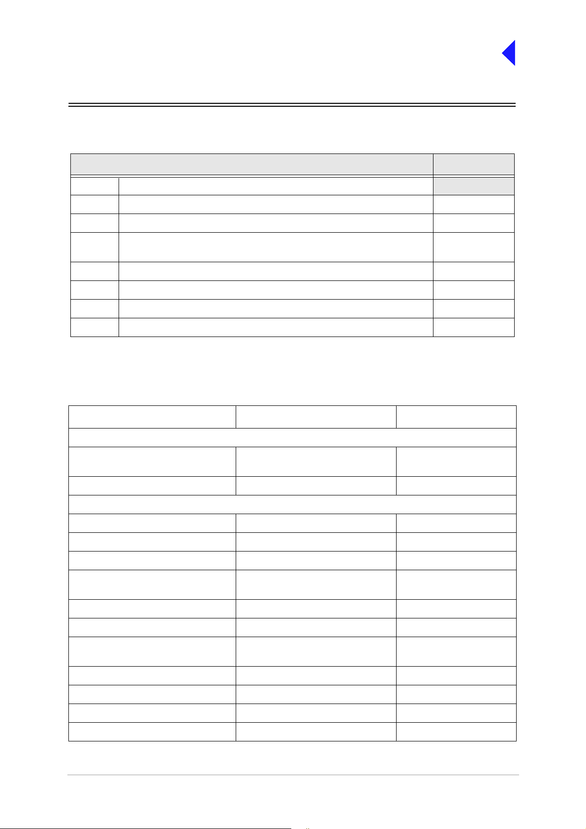
Introduction
The procedures necessary to install a transmitter are listed in Table 1.
Table 1 Installation Procedures
Procedure Reference
1 Read and understand the warnings and cautions given on page 2.
2 Perform an initial inspection of the tr ansmitter and fi t t he correct ac input fuse. page 9
3 Fit the transmitter into an equi pment cabinet. page 9
4 Make external signal connecti ons. See Fig 1 to Fig 5 to determine which
external connections are required f or the particular configuration.
5 Connect the chassis stud to the cabinet or system earth. page 22
6 Connect the antenna. page 22
7 Connect the dc input supply (if required). page 22
8 Connect the ac input supply (if required). page 23
page 10
Fuses and Connectors
The following list details the radio’s supply fuses and connectors. Some of the connectors (depending on
your particular configuration) are required during installation.
Table 2 Fuses and Connectors
Component T ype Park Air Part Number
Fuses:
AC input fuse, F2, for 110/120 V input
AC input fuse, F2, for 220/230 V input
DC input fuse 15A size 0 29-01350201
Connectors:
AC supply connector IEC 20-02030102
T4A, 125V, UL
T4A, 250V, IEC
29C11120102S
29E01120108S
DC supply connector XLR3 socket 20-01030106
Antenna connector N-type plug 19-01030301
MARC connector 9-way D-type plug Plug: 20-01090100
Cover: 20-09090101
MARC audio RJ48 plug 20K01080100
MARC data RJ48 pl ug 20K01080100
Facilities connector 15-way D-type plug Plug: 20-01150100
Cover: 20-09150101
HDLC connector RJ48 plug 20K01080100
T1/E1 connector RJ48 plug 20K01080100
Reference connector SMB connector 19C01050300
Microphone/Diagnostics connector 7-pin DIN plug 20-01070101
T6T VHF 50 W Transmitter Page 3 Installation
Page 47
Back to Tra n s mitter
Main Page
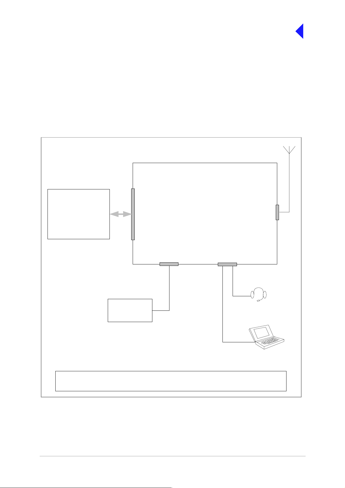
Configuration
Connection of external equipment depends on the configuration required. Possible configura tions are:
❑ T6T transmitter configured for local operation (see Fig 1).
❑ T6T transmitter configured for remote operation (see Fig 2).
❑ T6T transmitter configured for use with MARC (see Fig 3).
❑ T6T Mode 2 configuration (see Fig 4).
❑ T6T Mode 3 configuration. (see Fig 5).
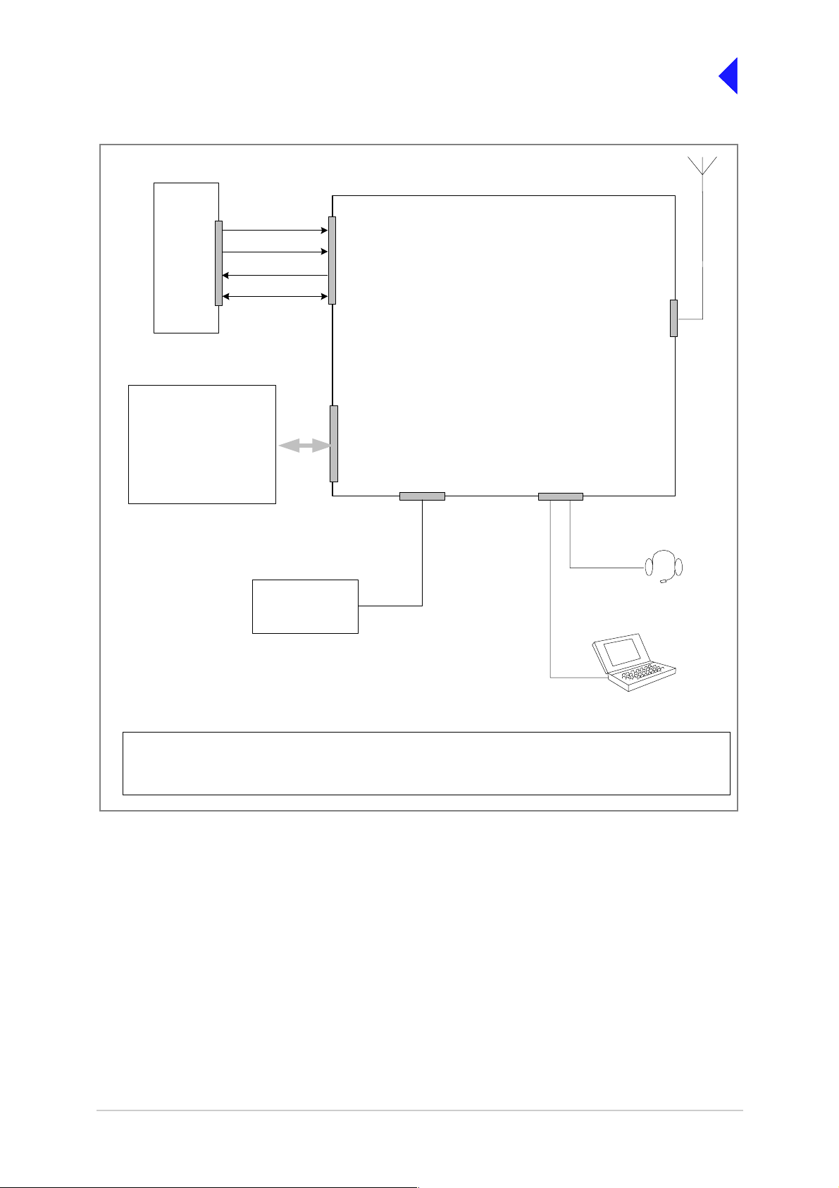
T6T Transmitter
Optional Facilities that
can be used if required
E-BIT input
PTT relay output
External VSWR input
Unregulated supply output
Inhibit input
BIT interruptive test input
Antenna changeover output
Ready output
Tape output
Facilities
Connector
Frequency Counter
required only for
maintenance
Reference
Connector
Antenna
Connector
Microphone/Diagnostics
Connector
Mic/Headset for
local operation
Laptop (or PC) required
only for maintenance
For local oper ati on, the transmitte r is operated from the front panel usi ng a m icrophone/headset.
Any of the optiona l fa cilities may be connect ed.
Fig 1 T6T Transmitter Configured for Local Operation
T6T VHF 50 W Transmitter Page 4 Installation
Page 48

T6T Transmitt e r
Back to Tra n s mitter
Main Page
Unregul ate d su pp ly
RS422 Data
Optional Facilities that
can be used if required
E-BIT input
PTT relay output
External VSWR input
Unregulated s upply output
Inhibit input
BIT interruptive test in pu t
Antenna changeover output
Read y output
Tape output
Audio
PTT
MARC Connector
or,
MARC Data and MARC Audio
Connectors
Facilities
Connector
Frequency Counter
required only for
maintenance
Reference
Connector
Antenna
Connector
Microphone/Diagnostics
Connector
Mic/Headset for
engineering use
Laptop (or PC) required
only for maintenance
For remote operation, Audio and PTT signals from the control equipment terminate on the MARC
connector, o r alt ernati vely on the M ARC Audio conn ector. If d ata is requi red by a compat ible dat a syste m,
the RS422 data lines termi nate on the MARC connector, or alternatively on the MARC Data connector.
Any of the optional facilities may be connected.
Fig 2 T6T Transmitter Configured for Remote Operation
T6T VHF 50 W Transmitter Page 5 Installation
Page 49
Back to Tra n s mitter
Main Page
RSE2
Equipment
Connector
Optional Fa c ilities that
can be used if required
PTT relay out put
External VSWR input
Unregulated supply output
BIT interruptive test input
Antenna changeover output
Unregulated supp ly
RS422 data
E-BIT input
Inhibit input
Ready output
Tape output
Audio
PTT
Freque nc y Counter
required only for
maintenance
MARC
Connector
Facilities
Connector
Reference
Connector
T6T Tra nsmitt e r
Antenna
Connector
Microphone/Diagnostics
Connector
Mic/Headset for
engineering use
Laptop (or PC) r equired
only for maintenance
When using a T6T transmitter with a MARC Remote Site Equipment (RSE2) the transmitter MARC
connector is pin-to-pin wired to one of the RSE2 Equipment connectors.
Any of the optional facilities may be connected.
Fig 3 T6T Transmitter Configured for use with MARC
T6T VHF 50 W Transmitter Page 6 Installation
Page 50

T6T Tra ns m itter
Reference
Connector
Microphone/Diagnostics
Connector
Antenna
Connector
Back to Tra n s mitter
Main Page
Mode 2
Network Computer
Reference connector
Control and data
T6R Receiver
Reference
Connector
Headset/Diagnostics
Connector
Connects to the
HDLC
Connector
T1/E1
Connector
Control and
data. 2 km
maximum
distance
T1/E1
Connector
Facilities
Connector
Antenna c/o control
Connector
Antenna
Fast Antenna
Change-Over
Switch
Frequency Counter
Connects to the
Microphone/Diagnostics
connector
Laptop (or PC) required
only for maintenance
required only for
maintenance
Fig 4 T6T Transm i t t er Mode 2 Conf ig urat i on
T6T VHF 50 W Transmitter Page 7 Installation
Page 51

T6T Transmitter
Back to Tra n s mitter
Main Page
Antenna
Connector
Mode 3
Network Computer
T1/E1
Connector
Control and data
Frequency Counter
required only for
maintenance
Reference
Connector
Microphone/Diagnostics
Connector
Fig 5 T6T Transm i tter Mode 3 Conf i gu ra tion
Laptop (or PC) required
only for maintenance
T6T VHF 50 W Transmitter Page 8 Installation
Page 52

Back to Tra n s mitter
Main Page
Installation Procedures
Initial Inspection of the Transmitter
On receipt of the transmitter, remove all transit packaging and check that there is no damage. If damage
is evident, contact Park Air immediately and retain the original transit packaging. One copy of the T6 User
Guide CD (part numbe r 31-36T62VCD) is normally supp lied with the transm itter. This CD includes the
VFP software.
Fitting the Corre ct AC Input Fuse
The mains input fuse F2 is an integral part of the rear panel ac connector. The fuse type must be correct
for the local mains supply as detailed below.
Earth
Line
For a mains input in the range 110 to 120 Vac, fuse
Neutral
Holder for spare
fuse (not supplied)
FS2
Spare Fuse
F2 should be rated T4A, 125V, UL.
For a mains input in the range 110 to 240 Vac, fuse
F2 should be rated T4A, 250V, IEC.
Fitting a Radio into an Equipment Cabinet
Caution Mechanical Support
It is essential that the chose n mechan ical installation provides a dequate s upport along the
depth (front to rear) of the unit. The transmitter must not be supported by the front panel;
doing so can cause damage.
The transmitter can be inst alled on telescopic slides, or on fixed runners, within a standard 4 83 mm
(19 inch) equipment cabinet. M4 tapped holes, each 10 mm deep (see Fig 6) are provided on each side
of the equipment to accept the slides. Details of suitable telescopic slides and fixed runners are available
from Park Air.
When fitted in th e cabinet, the t ransmitter's front panel m ust be secured to the c abinet’s chas sis using
four M6 x 16 mm screws and plastic washers.
T6T VHF 50 W Transmitter Page 9 Installation
Page 53

Front
Panel
29.0
41.7
47.0
152.8
207.5
232.2
430
Back to Tra n s mitter
Main Page
88.9
378.2
390.9
399
450
All measurements in mm
Fig 6 Sli de Fitt i ngs
Make External Signal Connections
Making the external signal connect ions invol ves configu ring th e transmitter to s uit its operational mo de.
Illustrations showing various configurations are shown in Fig 1 to Fig 5; these figures should be used only
as a guide.
Front Panel Connectors
The front panel has two connectors; Microphone/Diagnostics and Reference connectors. These are
illustrated in Fig 7.
Fig 7 Front Panel
T6T VHF 50 W Transmitter Page 10 Installation
Page 54

Back to Tra n s mitter
Main Page
Microp ho ne / D i agnostics Connector
The Microphone/Diagnostics connector is a self-locking 7-way DIN socket used for connecting a
microphone, microphon e/heads et or PC. The connector pin-out is detailed in Table 3.
Pin-out of the Microphone/Diagnostics connector looking into
the mating face of the cha ssis mounted socket.
A suitable free socket is detailed in Table 2 on page 3.
Table 3 Microphone/Diagnostics Connector
Pin Number Signal Characteristic Usage
1 Microphone gr ound 0 V Microphone/Headset
2 Transmit data RS232. 115200baud, 8data bits, 1 stop bit,
no parity, no handshaking.
3 Microphone PTT 0 V to PTT . Microphone/Headset
4 Receive dat a RS232. 115200 baud, 8 data bits, 1 stop bit,
no parity, no handshaking.
5 Sidetone – Microphone/Headset
6 Microphone i nput To ensure cor rect VOGAD operation, t he fol -
lowing microphone input levels are required:
Passive setting: between 2 and 35 mV
Active setting: bet ween 8and 140 mV.
7 Ground 0 V PC
PC
PC
Microphone/Headset
Reference Connector
The Reference connector is an SMB plug used to monitor the radio’s reference frequency. It monitors
the frequency at a level of 100 m V (±50 mV) with less than -10 dBc harmonics.
T6T VHF 50 W Transmitter Page 11 Installation
Page 55

Back to Tra n s mitter
Main Page
Rear Panel Connectors
The rear panel connectors are shown in Fig 8 and listed in Table 4 . Select which connectors are going
to be used and then make connections as required.
Table 4 Rear Panel Connector Usage
Connector Type Usage
AC Supply IEC Terminating the ac input supply.
DC Supply XLR 3-pin Terminating the dc input suppl y.
Antenna N-type Terminati ng the antenna feeder coaxi al cable.
External Speaker 3.5 mm stereo jack Connects an external loudspeaker for monitoring sidetone.
MARC 9-way D-type Used to connect to a MARC remote site equipment.
Used to connect a T6 contro ll er or hub.
Used to terminate rem ote audio and PTT signals when a
remote site equipment or T6 controller is not used.
MARC Audio RJ48 Used as an alternat ive to the MARC conne ctor fo r terminati ng
remote audio and PTT signals.
MARC Data RJ48 Used as an alternative to the MARC conne ctor fo r terminati ng
data signals to and from a compatible data system.
Facilities 15-way D-type Provides a number of optional faci lities that can be used as
required.
T1/E1 RJ48 Used for connecting the radio to a Mode 3 network computer,
connecting a transmitter and receiver together as a Mode 2
base station , or f or connecting to a digital voice and data network.
HLDC RJ48 Used to connect to a Mode 2 network computer.
ANTENNA
DANGER HIGH
RF VOLTAGES
CONNECT
ANTENNA
BEFORE
USE
T1/E1 HDLC
MARC
DATA
MARC
AUDIO
MARC FACILITIES
RATINGS
AC SUP PLY
48 - 62Hz
~ 110 - 240V ( +10%) 4A
POWER 400VA max
DC SUPPLY
21.6 - 32V 10A
SEE INSTALLATION INSTRUCTIONS BEFORE
CONNECTING SUPPLIES
DISCONNECT SUPPLIES WHEN NOT IN USE
FUSE F2
110-240V T4A 250V IEC
110V - 120V T4A 125V UL
FUSE F1
F15A 32V
SUPPLY
FUSE F2
FUSE F1
AC SUPPLY
DC SUPPLY
Fig 8 Rear Pan el (C onnectors)
T6T VHF 50 W Transmitter Page 12 Installation
Page 56
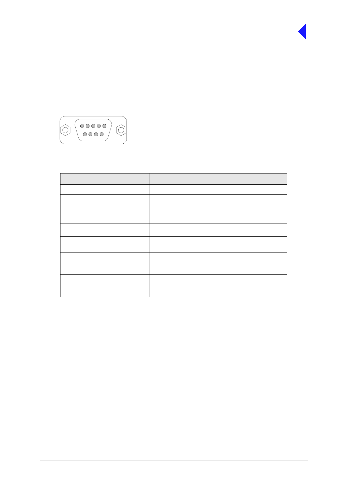
Back to Tra n s mitter
Main Page
MARC Connector
The MARC connector is a 9-way D-type socket used to connect the transmitter to a MARC remote site
equipment, or it can also be used for normal remote operation.
As an alternative to usin g this connec tor, the RJ 48 st yle M ARC A udio and M A RC Data connectors can
be used to provide the same functions.
The MARC connector pin-out is shown below and detailed in Table 5.
15
69
Pin-out of MARC connecto r looking in to the mati ng face of the
chassis mounted socket.
A suitable free socket is det ailed in Table 2 on page 3.
Table 5 MARC Connector
Pin Number Signal Characteristic
1 Ground 0 V
2
3
4 PTT input
5 Output supply This output is between 21.6 and 32Vdc (nominally
6
7
8
9
Audio line in (+)
Audio line in (-)
Data in (+)
Data In (-)
Data Out (+)
Data Out (-)
Balanced 600 ohm, -20 to +20 dBm.
Phantom keying can be superimposed on the audio
lines. See Fig 10.
Remote PTT signal i nput. See Fig 9.
28 V) fused at 500 mA.
RS422 differential asynchronous data at 9600 baud,
8 data bits, 1 stop bit, no pari ty, no handshaking.
RS422 differential asynchronous data at 9600 baud,
8 data bits, 1 stop bit, no pari ty, no handshaking.
Note ...
The line level figures shown for the MARC connector are the limits when testing the transmitter using
a sine wave; the line level will be 10 dB above the line level setti ng. See the informatio n supplied
under the heading ‘Line Level Settings’ in Operation.
T6T VHF 50 W Transmitter Page 13 Installation
Page 57

Back to Tra n s mitter
Main Page
MARC Audio Connector
The MARC Audio co nnector is an 8-way RJ48 socket. It can be us ed as an alternative to the MARC
connector for audio and PTT connections. The connector pin-out is shown below and detailed in Table 6.
Numbering is shown looking from the top of the connector.
RJ48 Plug
Pin 1
The top is being viewed when the lever is on the bottom.
Table 6 MARC Audio Connector
Pin Number Signal Characteristic
1
2
3 Fast antenna
4 Not used -
5 Not used -
6 PTT (input) Remote PTT signal input. See Fig 9.
7 Ground 0 V.
8 Not used -
Audio line in (input)
Audio line in +
(input)
changeover/PTT
(output)
Balanced 600 ohm, -20 to +20 dBm.
Phantom keying can be superi m posed on the audio
lines. See Fig 10.
Open collector NPN transi stor grounding output,
200 mA max, configurable n/o or n/c).
Note ...
The line level figures shown for the MARC Audio connector are the limits when testing the
transmitter using a sine wave; the line level will be 10 dB above the line level setting. See the
information supplied under the heading ‘Line Level Settings’ in Operation.
T6T VHF 50 W Transmitter Page 14 Installation
Page 58

Back to Tra n s mitter
Main Page
MARC or
MARC Audio
Connector
Control
Equipment
Audio
Cross-Site Lines
Audio line 1
Circuit
Audio line 2
PTT
PTT input requires at least 1 mA to operate.
PTT
Switch
V
PTT
Input will draw no more than 6 mA.
The transmitter reference voltage (0 V, +14 V or -14 V) is selected from the Polarities screen.
❑ PTT is active when V
❑ PTT is inactive when V
❑ Maximum value of V
differs from the transmitter reference voltage by more than ±10 V.
PTT
differs from the transmitter reference voltage by less than ±1 V.
PTT
is ±60 V with respect to transmitter reference voltage.
PTT
Example:
To use 0 V as the keying poten tial, V
= 0 V; set transmitter reference voltage to +14 V; set PTT In to STD.
PTT
T6T Transmit te r
MARC Audio Connector
audio is pins 1 and 2
PTT is pin 6
ground is pin 7.
MARC Connector
audio is pins 2 and 3
PTT is pin 4
ground is pin 1.
Reference Voltage
(0 V, +14 V or -14 V)
Set from front panel
Fig 9 Remote Keying
MARC or
Control
Equipment
Audio
Circuit
PTT
Switch
Audio lines with phantom keying
signal superimposed
V
PTT
MARC Audio
Connector
PTT input requires at least 1 mA to operate.
Input will draw no more than 6 mA.
To reduce the number of cross-site lines between the control site and the transmitter, phantom keying may be employed.
This method has t he keying potential (V
) superimposed on the audio lines instead of using a separate line.
PTT
The transmitter reference voltage (0 V, +14 V or -14 V) is selected from the Polarities screen.
❑ PTT is ac tive when V
❑ PTT is inactive when V
❑ Maximum value of V
differs from the t ransmit ter refer ence voltage by more than ±10 V.
PTT
differs from the t ransmit ter reference voltage by less than ±1 V.
PTT
is ±60 V with respect to transmitter reference voltage.
PTT
Example:
To use 0 V as the keying potential, V
= 0 V; set transmitter reference voltage to +14 V; set PTT In to STD.
PTT
T6T Tr a nsmitter
MARC Audio Connector:
Audio is pins 1 and 2
MARC Connector:
Audio is pins 2 and 3
Reference Voltage
(0 V, +14 V or -14 V)
Set from front panel
Fig 10 Phantom Keying
T6T VHF 50 W Transmitter Page 15 Installation
Page 59

Back to Tra n s mitter
Main Page
MARC Data Connector
The MARC Data conne ctor is an 8-way RJ48 socket. It can be used as an alternative to the MARC
connector for data connections. The connector pin-out is shown below and detailed in Table 7.
Numbering is shown looking from the top of the connector.
RJ48 Plug
Pin 1
The top is being viewed when the lever is on the bottom.
Table 7 MARC RJ48 Data Connector
Pin Number Signal Characteristic
1
2
3 Not connected -
4
5
6 Remote Supply ON/OFF 0 V to switch off.
7 Ground 0 V.
8 Output suppl y This output is between 21.6 and 32 Vdc (nominally
Data in (-)
Data in (+)
Data out (+)
Data out (-)
RS422 differen ti al asynchronous data, 9600 baud,
8 data bits, 1 stop bit, no parity, no handshaking.
RS422 differen ti al asynchronous data, 9600 baud,
8 data bits, 1 stop bit, no parity, no handshaking.
Note: Rear panel switc h must be in ON position for
this function to oper ate.
28 V) fused at 500 mA.
T6T VHF 50 W Transmitter Page 16 Installation
Page 60
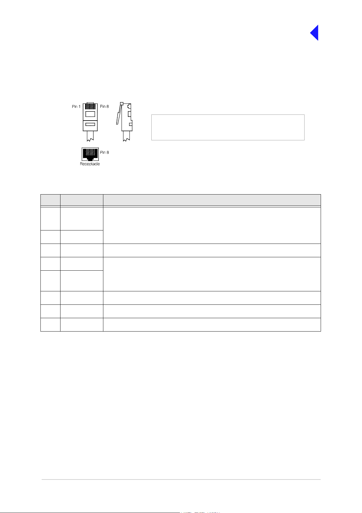
Back to Tra n s mitter
Main Page
T1/E1 Connector
The T1/E1 connector is an 8-way RJ48 socket used for connecting to a Mode 3 network computer or
connecting a transmitter and receiver together when operating as a Mode 2 base station. The connector
pin-out is detailed in Table 8.
Numbering is shown looking from the top of the connector.
RJ48 Plug
Pin 1
The top is being viewed when the lever is on the bottom.
Table 8 T1/E1 Connector
Pin Signal Characteristic
1 RRing T1 - Balanced 100 ohm (±10%), 1.544 Mbits per second (±50 ppm), AMI/B8ZS Coding.
E1 - Balanced 120 ohm (±10%), 2.048 Mbit s per second (±50 ppm), AMI/HDB3 Coding.
2RTip
3 Not connected -
4 TRing T1 - Balanced 100 ohm (±10%), 1.544 Mbits per second (±50 ppm), AMI/B8ZS Coding.
5TTip
6 Not connected -
7 Not connected 8 Not connected -
Protected with 28 V differential and common mode clamp and 1.25 A fuse in each line.
E1 - Balanced 120 ohm (±10%), 2.048 Mbit s per second (±50 ppm), AMI/HDB3 Coding.
Protected with 28 V differential and common mode clamp and 1.25 A fuse in each line.
T6T VHF 50 W Transmitter Page 17 Installation
Page 61
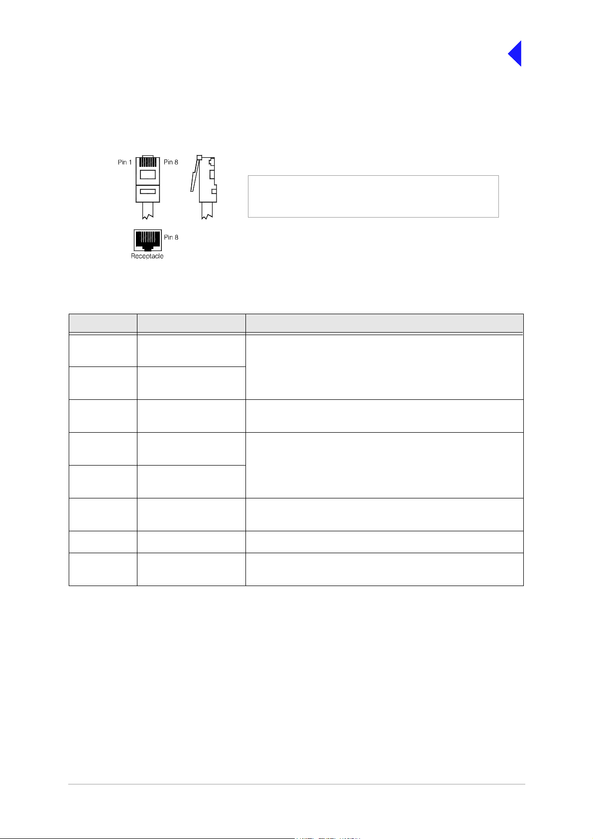
Back to Tra n s mitter
Main Page
HDLC Connector
The HDLC connector is an 8-way RJ48 socket used for connecting to a Mode 2 network computer. The
connector pin-out is detailed in Table 9.
Numbering is shown looking from the top of the connector.
RJ48 Plug
Pin 1
The top is being viewed when the lever is on the bottom.
.
Table 9 HDLC Connector
Pin Signal Characteristic
1 HDLC RX A
(input)
2 HDLC RX B
(input)
3 HDLC CL A
(output)
4 HDLC TX B
(output)
5 HDLC TX A
(output)
6 HDLC CL B
(output)
7 Ground 0 V.
8 Output supply This output is between 21.6 and 32 Vdc (nominally 28V) fused at
RS422 differential synchronous data, 128 kbytes per second
(±50 ppm ).
RS422 differential synchronous data, 128 kbytes per second
(±50 ppm ).
RS422 differential synchronous data, 128 kbytes per second
(±50 ppm ).
Pair to pin 3.
500 mA.
T6T VHF 50 W Transmitter Page 18 Installation
Page 62

Back to Tra n s mitter
Main Page
External Speaker
The External Speaker connector is a 3.5 mm stereo jack used for connecting an external speaker to the
transmitter to provide sidetone. This speaker should be a high impedance active type.
Table 10 External Speaker
Pin Signal Characteristic
Tip Speaker Drive (output) 0 to 3 V pk-pk. Connected directly to Ring.
Ring Speaker Drive (output) 0 to 3 V pk-pk. Connected direct ly to Tip.
Sleeve Ground 0 V.
T6T VHF 50 W Transmitter Page 19 Installation
Page 63
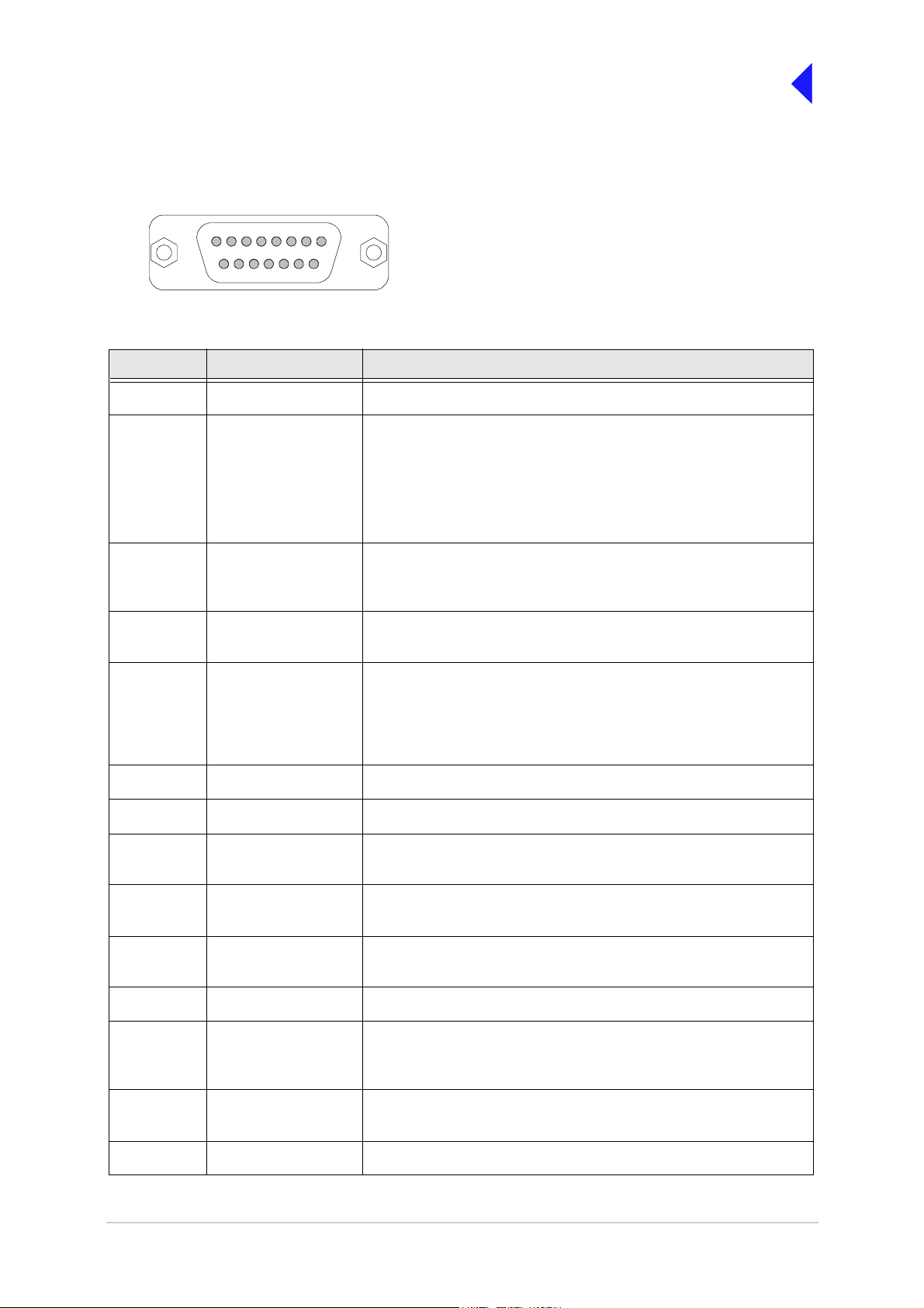
Back to Tra n s mitter
Main Page
Facilities Connector
The Facilities conne ctor is a 15-way D-type filtered soc ket used for connecting to associated parts of a
system. The connector pin-out is detailed in Table 11.
18
915
Pin-out of Facilities connector looking into the mating face of
the chassis mounted socket.
A suitable free socket is det ailed in Table 2 on page 3.
Table 11 Facilities Connector
Pin Number Signal Characteristic
1 Ground 0 V.
2 E-BIT (input) An external BIT input that connects from any ancillary equipment
having a compatible BIT alarm output.
When this input is active, the transmitter’s front panel Alarm indicator
flashes and an E-BIT mess age is di splayed on the di splay. The in put is
TTL having a 4.7 kohm pull-up resistor to 5 V. The input is
configurable from the front panel to be active high or low.
3 PTT output Grounding solid state relay. +60 to -60 V, ac or dc, 100 mA max,
configurab le n/o or n/c. Activated 35 ms (± 1 ms) before the start of the
power ramp up to allow for the antenna relay pull-in time.
4 External VSWR input Used to indicate an ext ernal VSWR fault. TTL input wit h 4.7 kohm pul l-
up to 5 V. Configurable active high or low.
5
6
7 Not used -
8 Ground 0 V.
9 Output supply This output is between 21.6 and 32Vdc (nominally 28 V) fused at
10 Inhibit (Input) Active signal prevents the transmitter keying. TTL with 4.7 kohm pull-
11 BIT interruptive test
12 Not use d -
13 Ready (output) An output that is active when the radio i s ready to transmit and no
14 Tape (output) An audio output for connection to a recording system. 0 dBm fixed
Antenna changeover
(output)
Antenna changeover
common (output)
(input)
Solid state rel ay linked to pin 6. See Fig 11 for further detail.
Solid state relay linked to pin 5.
500 mA.
up to 5 V. Configurable active high or low.
Active signal initiates a BIT test. TTL with 4.7 kohm pull-up to 5 V.
Configurable active high or low. Must be asserted f or >300 ms.
faults are detected. Open collect or NPN transistor grounding output,
200 mA max, configu rable n/o or n/c.
output into 600 ohm for 90% mod ulation depth.
15 Reserved (output) Do not connect to pin 15 unless advised to do so by Park Air.
T6T VHF 50 W Transmitter Page 20 Installation
Page 64

T6T Tr a nsmitter
(Main)
Facilities
Connector
Antenna
T6T Tr a nsmitter
(Standby)
Facilities
Connector
Solid State
Relay
Back to Tra n s mitter
Main Page
Antenna
28 Vdc (nominal)
Main/Standby
Transmit Relay
9
5
6
Link
8
Control
Antenna
Example
This example shows the Antenna Changeover Output configured to control the antenna switching between main
and standby transmitters. The potential on Facilities connector pin 6 is switched through to pin 5 when the standby
transmitter is keyed; in this example, pin 6 is linked to ground. This energizes the Main/Standby Transmit Relay to
route the standby transmitter to the antenna.
Other Configurations
The antenna changeover output can be confi gured in other wa ys to suit t he user’s requirement subject to:
❑ Pin 6 can be any potential between -60 and +60 Va c, or dc.
❑ The maximum current drawn must not exceed 100 mA.
❑ The output at pin 5 is configurable normally open or normally closed f rom the Polariti es screen.
❑ The internal solid state switch activates 35 ms before the start of the power ramp to allow for the antenna
relay pull-in time.
Fig 11 Example: Using the Antenna Changeover Output
T6T VHF 50 W Transmitter Page 21 Installation
Page 65

Back to Tra n s mitter
Main Page
Chassis Stud Connection
WARNING Chassis Earth
A chassis stud is fitted to the transmitter's rear panel. This stud is used to connect the
equipment to the equipmen t cabinet, or to the user's system earth point. The stud m us t not
be used as the safety earth.
In order not to compromise the transmitter’s Electromagnetic Compatibility (EMC) the chassis stud,
marked and fitte d to the rear panel (see Fig 8) must be connected to the equipment cabinet (if a
cabinet is being used) or to the user's system earth point. The connection should be made using a single
tri-rated, green-and-yellow cable having a cross-sectional area of 2.5 mm
2
. The cable should have CSA
and UL1015 approval, and be connected to the chassis stud through an M6 eyelet (for example, Park Air
part number 20-08010103).
Failure to comply with this instruction could result in non-compliance with the European
Commission EMC Directive 89/336/EEC.
Connect the Antenna
The antenna connector is an N-type socket suitable for connecting a 50 ohm antenna.
Connect the DC Input Supply
The transmitter operat es from e ither an ac, o r a dc input supply. W hen both ac and dc are connect ed,
operation from the ac supply takes priority; automatic change -over to the dc supply occurs if the ac
supply fails. On restoration of the ac supply, the equipment reverts to ac operation.
A dc input sup ply connector (see Fig 12) is fitted to the equipment's rear panel. The recommended
minimum rating of the dc supply cable is: 2-core having a cross-sectional area of 1.5 mm
supply cable should be fitted with an XLR 3-pin socket (Park Air part number 20-01030106).
Positive Negative
Pin-out of DC connector looking
into the m a tin g f ac e of the c ha s sis
mounted socket.
Not used
Fig 12 DC Connector
2
per core. The
T6T VHF 50 W Transmitter Page 22 Installation
Page 66

Back to Tra n s mitter
Main Page
Connect the AC Input Supply
WARNING Dangerous Voltages
The equipment is perman ently connected to the mains sup ply wh en th e mai ns c onnector is
attached. Switching the re ar panel Power sw itch to off does not isolate al l internal circuits
from the mains su pply. For this reas on, a mains isolating switch sh ould be fitted close to,
and easily accessible fro m, the transmitter's position. Th e isolation switch should isolate
both live and neutral supplies, be clearly labelled, and adequately rated to protect the
equipment.
WARNING Earth Connection
This equipment must be earthed. The earth terminal of the ac connector should be used as
the safety earth.
An ac input connector is fitted to the equipment ’s rear panel. Th e cable used t o connect bet ween the
equipment and the user’s ac power source should be 3-core (to IEC 227) rated 250 Vac at 8 amps, and
have a minimum c ross-sectional area of 1.0 mm
chloride (PVC) insulated cable. The cable must be fitted with the IEC approved equipment connector and
conform to the following specification:
2
per core. Park Air recommends t he use of polyvinyl
❑ If PVC insulated, be not lighter than ordinary polyvin yl chloride sheathed flexible cord acc ording
to IEC publication 227 (designation H05 VV-F, or H05 VVH2-F).
❑ If rubber insulated, be of synthetic rubber and not lighter than ordinary tough rubber-sheathed
flexible cord according to IEC publication 245 titled ‘Rubbe r Insulated Cables of Ra ted Voltages
up to and Including 450/750 V (designation H05 RR-F)’.
The T6T transmitter is a Class 1 equipment. The ac supply cable should have a green-and-yellow
protective earthing conductor electrically connected to the protective earthing terminal of the equipment
connector and the mains plug. Park Air recommends the ac supply cable is colour coded in accordance
with the electrical appliance (colour code) regulations for the UK. That is:
❑ The core coloured green-and-yellow must be
connected to the terminal in the plug that is
Earth
Line
marked with the letter E or by the earth symbol
or coloured green-and-yellow.
❑ The core coloured blue must be connected to
the terminal that is marked with the letter N or
Neutral
coloured black.
❑ The core coloured brown must be connected to
the terminal that is marked with the letter L or
coloured red.
Holder for spare
fuse (not supplied)
FS2
Spare Fuse
T6T VHF 50 W Transmitter Page 23 Installation
Page 67

Switching On
Back to Tra n s mitter
Main Page
WARNING
Dangerous Voltages
When the POWER SWITCH is set to the Standby position, dangerous voltages are still
present in the transmitter's internal power supply circuitry. To ensure safe working, the
transmitter must be isolated from the ac and dc input supplies
When installation is complete, the trans mitter should be switched on at the rear panel 2-way roc ker
Power switch. The Power switch is used to switch on, and switch off, power to the transmitter's circuitry
but does not remove power from the radio.
= Standby= On
Under normal circumstances this screen is displayed for a few seconds when the radio is switched on.
T 6 D i g i t a l R a d i o
( c ) 2 0 0 3 P a r k A i r
I n i t i a l i s i n g . . . .
. . . . . . . . . . . . . . .
The bottom row begins empty and dots are added as the initialisation progresses. When the initialisation
is complete the Main Screen is displayed.
Setting Up
When installation has been su ccessf ully com pleted the t rans mitter must be s et up using the f ront panel
conntrols or the VFP.
Setting up is detailed in the Operation section of this documentation.
When setting up the trans mitter, pay particular attention to the Polarities of any
functions that have been hard-wired during installation. For example, the polarity of
the PTT input and the polarity and configuration of the Antenna Changeover output.
Failure to select the correct settings will result in incorrect operation.
T6T VHF 50 W Transmitter Page 24 Installation
Page 68

Maintenance
Back to Transmitt e r
Main Page
Page 69

Back to Transmitter
Main Page
Introduction
This section gives the scheduled and unscheduled maintenance procedures for the T6T transmitter and
shows how to use the Virtual Front Panel (VFP).
Scheduled Maintenance A scheduled mainten ance procedure is given on page 3. Park Air
recommends that this task be completed every twelve months.
Unscheduled Maintenanc e Normally, the T6 transmitter is considered a Lin e Replaceabl e Unit
(LRU) and should be replaced with a serviceable spare if a fault
occurs. The faulty transmitter should then be returned to Park Air
for repai r.
In certai n cir cum stances, Park Air C
suggest that the user change one of the transmit ter modules.
Dismantling and assembly instructions are therefore given under
the heading Unscheduled Maintenance starting on page 7.
Using the VFP Operating parameters can be set from the transmitter front panel,
or by using the VFP. Some additional function s are available from
the VFP. See page 18.
ustomer Support may
T6T 50 W VHF Transmitter Page 2 Mai ntenance
Page 70

Back to Transmitter
Main Page
Scheduled Maintenance
Park Air recommends that scheduled maintenance is carried out at twelve-monthly intervals. Scheduled
maintenance comprises the following checks:
Number Check Tools/Test Equipment Required
1 Ensure the equipment is clean and that external
connectors are securely fitted.
2 Check and reset (if required) the transmitter's
frequency standard.
3 Perform a BIT interruptive test.
4 Perform an ac and dc change-over check (if bot h
supplies are connect ed).
Camel hair brush/clean lint-free
cloths
VHF Frequency Counter
Cleaning and Checking Security of Connectors
Remove all dust and dirt from the equipment's exterior using a lint free cloth and camel hair brush. Check
all external connections are secure and free from damage.
Setting the Transmitter’s Internal Reference Frequency
To set the transmitter’s internal reference frequency, use the following procedure. Note that references
to the switch in the procedure mean the Scroll/Select switch.
(1) Ensure the transmitter does not have
an offset
(2) Connect a frequency counter to the
front panel Reference connector.
(3) From the Main screen, press the switch
to display the Control screen. Turn the
switch until Settings is highlighted.
Press the switch.
F r e q u e n c y
C h a n n e l
S e t t i n g s
E x i t
Control Screen
(4) Ensure the Settings screen is
displayed. Turn the switch until Ref
Freq is highlighted, then press the
switch.
(5) With Ref Freq selected turn the switch
clockwise or anti-clockwise until the
frequency counter reads 20.950000
MHz ±10 Hz, then press the switch.
B a n d E d g e s
R e f F r e q 5 0 . 0 %
B a c k l i g h t 0 3 0 s
E x i t < < > >
Setti ngs Sc re e n
(6) Turn the switch clockwise until Exit is highlighted, then press the switch. You are returned to the
Main screen.
(7) Disconnect the frequency counter.
T6T 50 W VHF Transmitter Page 3 Mai ntenance
Page 71

Back to Transmitter
Main Page
(8) If not 5-carrier offset, refer to AM Voice Mode Settings Screen in the O peration section of this
document and set to the required offset.
(9) If 5-carrier offset is required, restore the carrier offset using the following routine:
❑ Connect a 50 ohm frequency counter, through a 60 dB atte nuator, to the transmitter’s rear
panel Antenna connector (see Fig 1 for location of the Antenna connector).
❑ Refer to AM Voice Mode Settings Sc reen in the Operation sec tion of this document and s et
the desired 5-carrier offset.
❑ Refer to Changing the Transmitter’s Operating Frequency in this document and set the
transmitter to the nearest 25 kHz chann el f requency . For exam ple, if the required frequ ency
is 124.504 (+4 kHz offset), set the transmitter to 124.500 MHz.
❑ Key the transmitter and adjust the reference frequency, using the front panel Scroll/Select
control, until the frequency counter disp lays the requ ired operating freque ncy. For ex ample
124.504 MHz.
❑ When the frequency count er displays t he exac t operat ing freque ncy, press the S croll/S elect
control and stop keying the transmitter.
❑ Disconnect the test equipment and reconnect the antenna.
T6T 50 W VHF Transmitter Page 4 Mai ntenance
Page 72

Back to Transmitter
Main Page
To Initiate a BIT Test
An interruptive BIT test cannot be initiated in Mode 2 or Mode 3.
During an interruptive BIT test, the t rans m itter radiates m odul ated c arrier waves at t he s et power.
Users should therefore obtain the necessary authority before initiating a test.
If the test is to be carried out with the antenna disconnected, ensure a load is fitted to the
transmitter's Antenna connector.
In order to test the line input stages, an internally generated 1 kHz tone is injected into the line input
circuit. Any other audio present on the line input will cause the test to be inaccurat e. Th erefore the
transmitter MUST NOT be keyed during the test.
(1) From the Main screen, press the s witch to
display the Control screen. Turn the switch
until BIT is highlighted. Press the switch.
(2) Ensure the BIT menu is displayed. Turn
the switch until BIT Initiate is highlighted.
Press the switch.
(3) During the test, which takes approximately
two seconds, the Testing screen is
displayed.
(4) After the test, either a Pass or Fail screen
is displayed. S electing OK t akes the u ser
back to the BIT screen.
B I T
S / W C o n f i g
S t a n d b y
E x i t < <
B I T I n i t i a t e
E T I 0 0 0 0 0 : 0 0 h r s
A C S u p p l y O N
E x i t > >
T e s t i n g
P l e a s e W a i t
T e s t S t a t u s
P A S S
O K
(5) If fail is displayed, scroll through the screen
T e s t S t a t u s
to check the cause of the failure.
F A I L
O K
T6T 50 W VHF Transmitter Page 5 Mai ntenance
Page 73

Back to Transmitter
Main Page
AC and DC Change-over Check
If both ac and dc input supplies are connected to the transmitter, carry out the following check:
(1) Confirm that both ac and dc supplies are connected to the transmitter. Ensure that the rear panel
Powe r switch is se t to the I ( o n ) p o s i tion.
(2) Confirm that the front panel Ready indi cator is lit, the LCD is illuminated, and the tran smitter is
operational.
(3) Switch off the ac supply from its source.
(4) Check that the trans mitter continues to operate correctly from the d c supply. If accessed, the
front panel BIT screen will show AC S upply as off, and DC supply as o n. The value of the dc
supply is also shown.
T6T 50 W VHF Transmitter Page 6 Mai ntenance
Page 74

Back to Transmitter
Main Page
Unscheduled Maintenance
WARNING Dangerous Voltages
The instructions given in this document involve connecting dangerous voltages to the
transmitter. Maintenance should be carried out only by suitably qualified personnel.
When an ac supply is connected, dangerous voltages are present within the transmitter. Care
must be taken by personnel to avoid accidental contact with exposed circuitry during
maintenance or alignment procedures.
When the power swit ch is set to the S tandby pos ition, dangero us voltages a re still present
in the transmitter's internal power sup ply circuitry. To ensure safe working, the ac an d dc
input supplies must be disconnected from the transmitter.
WARNING
The antenna used with the transmitter must be installed such that the resultant radiated field
strength is below 10 W/m² in areas normally accessible to personnel.
Caution
The T6 transmitter's ci rcuitry contains Electrostatic Sensitive De vices (ESSDs). Personnel
must be aware of the precautions necessary to prevent damag e to such devic es.
Caution Unauthorized Modifications
Changes or modifications made to this equipment that are not expressly approved by
Park Air, or parties authorized by Park Air, could void the user’s authority to operate the
equipment.
Caution Repairs
When carrying out repairs to the PA module, care must be taken not to damage the gasket.
If the strips become damaged, they must be replaced. Failure to comply with this instruction
may compromise the transmitter’s Electromagnetic Compatibility (EMC) and breach
European Commission regulations.
Antenna Radiation
ESSDs
When screws ar e i nse rted into th e transmitter PA casting care must be taken n ot to ex ceed
a torque of 6 Ibs/inch when tightening. This applies when replacing the top and bottom
covers and during the refitting of the PA module.
T6T 50 W VHF Transmitter Page 7 Mai ntenance
Page 75

Back to Transmitter
Main Page
Introduction
This document provides the us er with detailed instruc tions on the remov al an d replacem ent of modul es
and assemblies.
(1) When removing or refitting modules, observe antistatic handling precautions.
(2) Do not change any potentiometer (or link) settings unless detailed in these instructions.
Potentiometers have been set using specialist equipment.
(3) The transmitter uses the following Molex KK connectors:
CN2 on the PA Control module
CN7 and CN6 on the PSU Regulator module.
To remove KK type connectors:
❑ Free the locking mechanism on the c onnect or by moving one side of the conne ctor up, then
move the other side up (see the following diagram). The upward motion should only be as far
as needed to free the locking mechanism
❑ DO NOT pull the cable to free the connector
❑ Note that KK type connectors are designed to be removed in this manner to free the locking
mechanism. Do not use this procedure with non-KK type connectors as damage to the
connector may occur.
Lift 2Lift 1
PCB
Tools, Materials and Test Equipment Required
The following tools, materials and test equipment should be made available to complete the
maintenance tasks descri b ed in thi s sec tion:
❑ Personal Computer (PC)
❑ General Purpose Tool kit (including a
1.5 mm Allen key)
❑ 5 mm Nut Spinner
❑ Camel Hair Brush
❑ Clean Lint-free Cloths
❑ Frequency Counter
❑ Power Meter
❑ Dummy Load
❑ P C to Radio Interconnection Lead
(Park Air part number 17E12600001)
❑ SMB to BNC Lead for reference frequency
(Park Air part number 17K11000004)
T6T 50 W VHF Transmitter Page 8 Mai ntenance
Page 76

Back to Transmitter
Main Page
Top Cover
To remove the top cover, locate and unscrew the 18 countersunk s crews securing the top cover to the
mainframe. Access can then be gained to the following modules:
❑ Processor module
❑ P SU Regula tion module
❑ P owe r Supply (requires top cover and bottom cover to be removed)
❑ RF PA module (requires top cover and bottom cover to be removed)
❑ F ront Panel assembly P CB (requires top cover and bottom cover to be removed)
Removing and Refitting the Processor Module
The Processor module is located as shown in Fig 3. A module removal diagram is shown in Fig 4.
WARNING Dangerous Voltages
Dangerous voltages are presen t within the transmitter. Care must b e taken by personn el to
avoid accidental contact with exposed circuitry when the top cover is removed and power is
appl i ed to the r adio.
Removal
Before attempting to remove the Processor module, and if possible, save the radio’s settings. To achieve
this connect a PC with the VFP software loaded to the radio using the PC to Radio Interconnection Lead
(Park Air part number 17E12600001). With the VFP software active, upload the radio settings to a
specified file.
Ensure that the transmitter is isolated from the ac and dc input supplies. Then proceed as follows:
(1) Unscrew the 18 countersunk screws and remove the transmitter’s top cover.
(2) Locate the Processor module (Fig 3) and disconnect the following connectors (Fig 4):
❑ CN1 50-way connector (50-way ribbon cable from PA Control module)
❑ CN3 14-way connector (14-way ribbon cable from PSU Regulator module)
❑ CN4 34-way connector (34-way ribbon cable from Front Panel module).
(3) Gain access to the rear of the transmitter. Using a 5 mm nut spinner tool, remove the four
screwloc 8 mm-4-40 UNC screws that secure the Processor module interface connectors CN5
and CN6 to the rear panel.
(4) Remove the seven M3 x 8 mm screws that secure the module to the transmitter’s mainframe.
(5) Remove the module from the chassis.
Refitting
To refit the Processor module, proceed as follows:
(1) Place the module in position. Ensure no wires are trapped by the mod ule. En sure jump er J2 on
the module is set to ‘T’ for transmitter (see the following diagram).
T6T 50 W VHF Transmitter Page 9 Mai ntenance
Page 77

Back to Transmitter
Main Page
JP2
Shown set for
transmitter
T2
T3
IC20IC19
IC21
TS7
C84
R/TR
R/TR
IC25
IC27
IC38
T
T
(1) Ensure the module’s interface connectors CN5 an d CN6 are located correctly and are aligned
with the screw holes in the rear panel. Fit the four screwloc 8 mm-4-40 UNC screws and wavy
washers but leave them loose.
(2) Fit the 11 (Mod Strike 5 modules), 7 (Mod Strike 6 and 7 modules) M3 x 8 mm screws that secure
the module to the transmitter’s mainframe, but leave them loose.
(3) Using a 5 mm nut spinner, tighten the four screwloc 8 mm-4-40 UNC screws and wavy washers
that secure the connec tors; then tighten the 11 (Mod Strike 5 mo dules), 7 (Mod S trike 6 and 7
modules) M3 x 8 mm screws that secure the module to the transmitter’s mainframe.
(4) Refit the following connectors to the module:
❑ CN1 50-way connector (50-way ribbon cable from PA Control module).
❑ CN3 14-way connector (14-way ribbon cable from PSU Regulator module).
❑ CN4 34-way connector (34-way ribbon cable from Front Panel module).
(5) Re-establish the ac and/or dc supplies (take heed of the warning on page 9).
(6) Switch power on at the radio using the rear mounted Power switch.
(7) Ensure the front panel Ready indicator is lit and the Alarm indicator is unlit.
(8) If a new module has been fitted, connect the VFP PC to the radio using the PC to Radio
Interconnection Lead, P ark A ir p art num ber 17E12600001 (if no t already connected). Note that
any module sent from Park Air as a spare for a particular radio will be programmed with
compatible operating and Fill software. P ark Air keeps records of module software in all radios
supplied. Care must be taken when using a module removed from another radio as this module
may not have compatible software.
(9) Download the saved radio settings from file using the VFP. Alternatively, the settings can be
edited by hand as described in the Operation section of this
document Once entered, ensure the required settings appear in the VFP screen.
(10) Carry out the Calibrate routine using the VFP, as detailed in the procedure To C alibrate the
Transmitter on page 22.
(11) Carry out a BIT interruptive test as detailed in the procedure To Initiate a BIT Test on page 5.
(12) Set the transmitter’s internal reference frequency by carrying out the procedure detailed on
page 3.
T6T 50 W VHF Transmitter Page 10 Maintenance
Page 78

Back to Transmitter
Main Page
(13) Remove the VFP connector and switch power off at the transmitter using the rear mounted
Power switch. Isolate the transmitter from the ac and/or dc supplies.
(14) Refit the transmitter’s top cover (take note of repairs caution (1) on page 7 before carrying out
this task). The transmitter can now be returned to service.
Removing and Refitting the PSU Regulator Module
The PSU Regulator module is located as shown in Fig 3. A module removal diagram is shown in Fig 5.
Removal
Before attempting to remove the PSU Regulator module, ensure that the transmitter is isolated from the
ac and dc input supplies. Then proceed as follows:
(1) Remove the transmitter’s top cover as described on page 9 (tak e heed of the warn i ng).
(2) Locate the PSU Regulator module and remove the three M3 x 8 mm captive washer screws that
secure the module to the transmitter’s mainframe.
(3) Carefully raise the module to gain access to the module connectors.
(4) Disconnect the following connectors:
❑ CN5 10-way connector (10-way ribbon cable to PA Control module)
❑ CN6 6-way connector (2-way loom to power supply). Note caution (3) on page 8
❑ CN4 14-way connector (14-way ribbon cable to Processor module)
❑ CN3 3-way connector (3-wire loom to PA module)
❑ CN7 3-way connector (3-wire loom to rear panel On/Off switch). Note caution (3) on page 8
❑ CN2 2-way connector (2-wire loom from dc input connector on rear panel)
❑ CN1 4-way connector (4-wire cable from power supply)
❑ CN9 2-way connector (2-wire cable ac input to power supply)
❑ CN8 3-way connector (2-wire loom to rear panel ac input connector plus chassis connection).
(5) Remove the module from the chassis.
Refitting
To refit the PSU Regulator module, proceed as follows:
(1) While holding the module in position, connect the following connectors:
❑ CN8 3-way connector (2-wire loom to rear panel ac input connector plus chassis connection)
❑ CN9 2-way connector (2-wire cable ac input to power supply)
❑ CN1 4-way connector (4-wire cable from power supply)
❑ CN2 2-way connector (2-wire loom from dc input connector on rear panel)
❑ CN7 3-way connector (3-wire loom to rear panel On/Off switch)
❑ CN3 3-way connector (3-wire loom to PA module)
❑ CN4 14-way connector (14-way ribbon cable to Processor module)
❑ CN6 6-way connector (2-way loom to power supply)
❑ CN5 10-way connector (10-way ribbon cable to PA Control module).
(2) Locate the module in position. Ensure no wires are trapped by the module.
T6T 50 W VHF Transmitter Page 11 Maintenance
Page 79

Back to Transmitter
Main Page
(3) Secure the module to the transmitter’s mainframe using the three M3 x 8 mm captive washer
screws removed during the removal procedure.
(4) Re-establish the ac and/or dc supplies (take heed of the warning on page 7).
(5) Switch power on at the radio using the rear mounted Power switch.
(6) Ensure the front panel Ready indicator is lit and the Alarm indicator is unlit.
(7) Carry out a BIT interruptive test as detailed in the procedure To Initiate a BIT Test on page 5.
(8) Switch power off at the transmitter using the rear mounted Power switch. Isolate the transmitter
from the ac and/or dc supplies.
(9) Refit the transmitter’s top cover. The transmitter can now be returned to service.
Bottom Cover
To remove the bottom cover, locate and unscrew the 15 countersunk screws securing the bottom cover
to the mainframe. Access can then be gained to the following modules:
❑ P A Cont rol modu le
❑ P owe r Suppl y (requires top and bottom covers to be removed)
❑ P A mod ule (requires top and bottom covers to be removed)
❑ F ront Panel assembly (requires top and bottom covers to be removed).
WARNING Dangerous Voltages
Dangerous voltages are presen t within the transmitter. Care must b e taken by personn el to
avoid accidental contact with exposed circuitry when the bottom cover is removed and
power is applied to the radio.
Removing and Refitting the PA Control Module
The PA Control module is located as shown in Fig 3. A module removal diagram is shown in Fig 6.
Removal
Before attempting to remove the PA Control module, ensure that the transmitter is isolated from the ac
and dc input supplies. Then proceed as follows:
(1) Remove the transmitter’s bottom cover as described above (take heed of the warning).
(2) Locate the module and disconnect the following connectors:
❑ CN1 50-way connector (50-way ribbon cable from Processor module)
❑ CN6 10-way connector (10-way ribbon cable from PSU Regulator module)
❑ CN5 SMB connector (reference frequency)
❑ CN3 SMB connector (RF drive)
❑ CN4 SMB connector (forward power sense)
❑ CN2 6-way connector (5-wire loom to PA module).
(3) Remove the seven M3 x 8 mm captive washer screws that secure the module to the transmitter’s
mainframe.
(4) Remove the module from the chassis.
T6T 50 W VHF Transmitter Page 12 Maintenance
Page 80

Back to Transmitter
Main Page
Refitting
To refit the PA Control module, proceed as follows:
(1) Place the module in position. Ensure no wires are trapped by the module.
(2) Fit the seven M3 x 8 captive washer screws that secure the module to the transmitter’s
mainframe.
(3) Refit the following connectors to the module:
❑ CN2 6-way connector (5-wire loom to PA module)
❑ CN4 SMB connector (forward power sense)
❑ CN3 SMB connector (RF drive)
❑ CN5 SMB connector (reference frequency)
❑ CN6 10-way connector (10-way ribbon cable from PSU Regulator module)
❑ CN1 50-way connector (50-way ribbon cable from Processor module).
(4) Re-establish the ac and/or dc supplies (take heed of the warning on page 12).
(5) Switch power on at the radio using the rear mounted Power switch.
(6) Ensure the front panel Ready indicator is lit and the Alarm indicator is unlit.
(7) Carry out the Calibrate routine using the Virtual Front Panel (VFP), as detailed in the procedure
To Calibrate the Tr ansm itter on page 22.
(8) Carry out a BIT interruptive test as detailed in the procedure To Initiate a BIT Test on page 5.
(9) Set the transmitter’s internal reference frequency by carrying out the procedure detailed on
page 3.
(10) Remove the VFP connector and switch power off at the transmitter using the rear mounted
Power switch. Isolate the transmitter from the ac and/or dc supplies.
(11) Refit the transmitter’s bottom cover. The transmitter can now be returned to service.
Removing and Refitting the Power Supply
The Power Supply is located as shown in Fig 3. A module removal diagram is shown in Fig 7.
Removal
Before attempting to rem ove the Power Supply, ensure t hat the trans mitter is isolated fr om the ac and
dc input supplies. Then proceed as follows:
(1) Remove the transmitter’s top and bottom covers as described on page 9 and page 12 (take heed
of the warnings on those pages).
(2) Support the radio on its side.
(3) Locate the power supply. From the bottom half of the unit remove the four No. 6 x 32 UNC
countersunk screws that se cure the power supply to the transmitter’s mainframe. During this
operation support the power supply from the top half of the unit.
(4) Withdraw the power suppl y from the chassis sufficient to allow access to the power terminal
blocks taking care not to damage the ac terminal plastic supply guard.
(5) Remove the connector CN4 (power supply to the power regulator).
(6) Disconnect the dc wires from the eight connector terminal block.
T6T 50 W VHF Transmitter Page 13 Maintenance
Page 81

Back to Transmitter
Main Page
(7) Slide back the terminal block cover and disconnect the ac wires from the three connector terminal
block (marked L N E).
(8) Carefully remove the power supply from the transmitter.
Refitting
(1) With the transmitter on its side hold the power supply near to its securing position in the top half
of the radio.
(2) Slide back the terminal block cover and connect the ac wires to the three connector terminal
block (marked L N E); brown to terminal L, blue to terminal N and yellow/green to terminal E.
(3) Connect the dc wires to the eight connector terminal block; red to terminal 2 and terminal 3 and
black to terminal 6 and terminal 7.
(4) Connect connector CN4.
(5) Taking care not to damage the plastic supply guard, lower the power supply into position and
secure from the bottom half of the unit using the four countersunk screws.
(6) Re-establish the ac and/or dc supplies.
(7) Switch power on at the radio using the rear mounted Power switch.
(8) Ensure the front panel Ready indicator is lit and the Alarm indicator is unlit.
(9) Carry out a BIT interruptive test as detailed in the procedure To Initiate a BIT Test on page 5.
(10) Switch power off at the transmitter using the rear mounted Power switch. Isolate the transmitter
from the ac and/or dc supplies.
(11) Refit the transmitter’s top and bottom covers. The transmitter can now be returned to service.
Removing and Refitting the PA Module
The PA module is located as shown in Fig 3. A module removal diag ram is shown in Fig 8.
Removal
Before attempting to remove t he PA module, ensure that the transm itter is isolated from the ac and dc
input supplies. Then proceed as follows:
(1) Remove the transmitter’s top and bottom covers as described on page 9 and page 12 (take heed
of the warnings on those pages).
(2) Remove CN3 from the PSU Regulator module.
(3) With the transmitter upside-down disconnect CN2 from the PA Control module.
(4) Disconnect the SMB connectors CN8 and CN10. Note that CN10 is located within the heatsink
fins and should be disconnected using long nosed pliers. Do not attempt to remove the connector
by pulling on the cable.
(5) Remove the black equipment handle from the PA side of the radio by unscrewing and removing
the two M5 x 16 mm panhead screws that secures it to the transmitter.
(6) Remove the six M3 x 8 mm countersunk screws and two M3 x 8 mm captive screws that secure
the PA from t he bottom and top of the mainfram e as show n in Fig 8. Ensure the PA module is
well supported during this operation.
(7) Withdraw the PA module from the mainframe taking care not to snag the wiring looms.
T6T 50 W VHF Transmitter Page 14 Maintenance
Page 82

Back to Transmitter
Main Page
Refitting
To refit the PA module, proceed as follows:
(1) Place the module in position and butt it up to the mainframe. Ensure no wires are trapped by the
module.
(2) Fit the six M3 x 8 countersunk screws and two M3 x 8 mm captive screws that secure the module
to the transmitter’s mainframe.
(3) Fit the black equipment handle to the PA side of the radio using the two M5 x 16 mm panhead
screws.
(4) Connect the SMB connectors CN8 and CN10. Note that CN10 is located within the heatsink fins
and should be connected using long nosed pliers if unable to use fingers in the enclosed space.
(5) With the transmitter upside-down connect CN2 to the PA Control module.
(6) Fit CN3 to the PSU Regulator module.
(7) Re-establish the ac and/or dc supplies.
(8) Switch power on at the radio using the rear mounted Power switch.
(9) Ensure the front panel Ready indicator is lit and the Alarm indicator is unlit.
(10) Carry out the Calibrate routine using the Virtual Front Panel (VFP), as detailed in the procedure
To Calibrate the Tr ansm itter on page 22.
(11) Carry out a BIT interruptive test as detailed in the procedure To Initiate a BIT Test on page 5.
(12) Remove the VFP connector and switch power off at the transmitter using the rear mounted
Power switch. Isolate the transmitter from the ac and/or dc supplies.
(13) Refit the transmitter’s top and bottom covers. The transmitter can now be returned to service.
Removing and Refitting the Front Panel Assembly PCB
The Front Panel assembly is located as shown in Fig 3. An assembly and PCB removal diagram is shown
in Fig 9.
Removal
Before attempting to remove the Front Panel assembly PCB, ensure that the transmitter is isolated from
the ac and dc input supplies. Then proceed as follows:
(1) Remove the transmitter’s top and bottom covers as described on page 9 and page 12 (take heed
of the warnings on those pages).
(2) Disconnect CN4 at the Processor module. Carefully pull the cable through the aperture in the
mainfram e to fr e e it.
(3) Disconnect SMB connector CN5 at the PA Control module.
(4) Remove the four M3 x 8 mm countersunk screws from the bottom and top of the mainframe box
section (see Fig 9, Diagram A).
(5) Remove the t wo black equipm ent handles by unscrewing and removing the four M5 x 16 m m
panhead screws that secure them to the transmitter. The front panel can now be moved forward
and away from the mainframe.
(6) At the front panel, release the control knob by unscrewing the Allen head grub screw using a
1.5 mm Allen key. Withdraw the control knob from the spindle.
T6T 50 W VHF Transmitter Page 15 Maintenance
Page 83

Back to Transmitter
Main Page
(7) Remove the Front Panel PCB from the Front Panel assembly by removing the six M3 x 6 mm
panhead screws and wavy washers (see Fig 9 Diagram B).
Refitting
To refit the Front Panel assembly PCB, proceed as follows:
(1) Place the PCB in position at the Front Panel assembly. Ensure the spindle of the control knob
and microphone/diagnostics connector are correctly located. Secure the PCB to the Front Panel
assembly using the six M3 x 6 mm panhead screws and wavy washers (see Fig 9, Diagram B).
(2) At the front panel, place the control knob onto the spindle and using a 1.5 mm Allen key, secure
the Allen head grub screw.
(3) Secure the Front Panel assem bly to the top and bot tom of the mainfr am e box se ction using the
four M3 x 8 mm countersunk screws. Fit the two black equipment handles using the four
M5 x 16 m m panh ead screws (see Fig 9, Diagra m A).
(4) Route the ribbon cable to the Processor module connector CN4 and connect it.
(5) Route the SMB connector to CN5 on the PA Control module and connect it.
(6) Re-establish the ac and/or dc supplies.
(7) Switch power on at the radio using the rear mounted Power switch.
(8) Ensure the front panel Ready indicator is lit and the Alarm indicator is unlit.
(9) Carry out a BIT interruptive test as detailed in the procedure To Initiate a BIT Test on page 5.
(10) Switch power off at the transmitter using the rear mounted Power switch. Isolate the transmitter
from the ac and/or dc supplies.
(11) Refit the transmitter’s top and bottom covers. The transmitter can now be returned to service.
Removing and Refitting the Cooling Fan
The cooling fan is at the rear of the PA module as shown in Fig 3. An assembly and removal diagram is
shown in Fig 10.
Removal
Before attempting to remove the fan, ensure that the transmitter is isolated from the ac and dc input
supplies. Then proceed as follows:
(1) Disconnect the two-pin connector.
(2) Remove fan's finger guard.
(3) Using an Allen key, inserted through the holes in the fan exposed with the finger guard removed,
remove the three M4 x 12 mm c aphead Allen screws that secure the fan to the PA module
heatsink.
(4) Remove the fan from the PA module.
Refitting
To refit the cooling fan, proceed as follows:
(1) Locate the fan in position and using a suitable All en key inserted through the holes for the fan's
finger guard, secure using the three M4 x 12 mm caphead Allen screws.
(2) Secure the finger guard to the fan.
T6T 50 W VHF Transmitter Page 16 Maintenance
Page 84

Back to Transmitter
Main Page
(3) Connect the 2-pin fan connector to the fan. Ensure the + marked socket mates with the + marked
plug on the fan.
(4) Re-establish the ac and/or dc supplies.
(5) Switch power on at the radio using the rear mounted Power switch.
(6) Ensure the front panel Ready indicat or is lit and the Alarm indica tor is unlit. The transmitte r can
now be returned to service.
T6T 50 W VHF Transmitter Page 17 Maintenance
Page 85

Back to Transmitter
Main Page
Virtual Fr ont Panel (VFP)
Virtual Front Panel (VFP) software is supplied on CD-ROM and is compatible with any PC or laptop
running Windows 2000™ or Windows XP™ . The VFP allows changes to a radio’s settings and channel
information, it displays the current BIT state, displays BIT history, allows security locks to be set, and
provides maintenance facilities.
A radio can be set up using the front panel Scroll/Select switch and LCD, or by using the VFP. Using the
VFP has several advantages over setting the transmitter from the front panel; these are:
❑ A profile of the transmitter’s operation settings and channel information can be created, stored on
disk, and then recalled to download into other transmitters.
❑ A print out of the transmitter’s profile can be made from the VFP.
❑ F ront Pan el Lock is available only when us ing the VFP. As part of the transm itter’s Settings (see
typical screen display shown below), Front Panel Lock can be set to ON. When selected to on, no
settings or frequency information can be changed from the front panel.
❑ I f the transmitter is part of a M ARC system or opera tes in a dig ital mode, a M ARC Lock, HDLC
Lock and T1E1 Lock are availa ble when using the VFP. When selecte d to on, no settings or
frequency information c an be changed f rom the MARC equ ipment screen, or the d igital control
equipment.
Typical VFP Screen - AM-Voice Profile Shown
T6T 50 W VHF Transmitter Page 18 Maintenance
Page 86

Back to Transmitter
Main Page
Installing the VFP Software
The VFP software is supplied by P ark Air on CD-ROM . The s oftwa re can be run f rom the Mai n page o r
installed on your PC via Explorer.
To install the software onto your PC:
(1) Using explorer, display the contents of the CD-ROM supplied by Park Air. Identify the file named
S0473Vxx.EXE (where xx is the version number).
(2) Using the mouse, right click on the file and then select Copy.
(3) Display the Windows desktop. Right click anywhere on the desktop and select Paste.
(4) Check that the VF P icon is shown on the desk top. Reposition the icon as required . The VFP
application is now installed on the PC’s desktop.
VFP Icon
VFP Features
The VFP screen is divided into four main windows: Settings, Channels, BIT and Status Information. Four
colours are used to display text. The colours have the following meanings:
❑ B la ck indicates a valid paramete r that has been accepted by the radio.
❑ Red indicates an invalid parameter that has been rejected by the radio, or a BIT failure.
❑ Green indicates text that has not yet been downloaded to the radio. Text loaded into the VFP from
a previously stored file, or any text that is manually amended is green until it is downloaded into
the radio; after being downloaded into the radio the text changes to black, or if it is invalid, to red.
❑ Blue indicates Help text and is shown in the Status Information window.
The Menu Bar
The menu bar has four categories: File, Serial Port, Radio and Help.
FileHas the sub-categories: Open, Save and Print. These sub-categories allow the user to open
previously saved profiles, save a new profile, or print a profile.
A special sub-category: File > Save > Diagnostics should only be used when advised by Park Air.
Serial PortHas the sub-categories: Com 1 an d Com 2. Before the VFP can be used, the appropriate
Com 1 or Com 2 must be selected to correspond with the PC’s Com Port used for the radio connection.
RadioHas the sub-categories: Retrieve, Send, Calibrate and Test.
This category allows a radio’s prof ile to be loa ded i nto the VFP , a llows a profile to be d ownloa ded f rom
the VFP to a radio, calibrates a radio and initiates a BIT test.
HelpProvides detail about the VFP software.
Settings Window
This window lists all attributes th at can b e adjusted by the us er. If any individual attribute is clicked on
using the mouse, help information is displayed in the Status Information window showing the range of
adjustment for that attribute. Click on the value and use the keyboard to amend it; press Enter to confirm
the new value noting that the amended text is green until it is downloaded into the radio.
T6T 50 W VHF Transmitter Page 19 Maintenance
Page 87

Back to Transmitter
Main Page
Any invalid parameters are not indicated until the Settings are downloaded to the radio. It is the radio that
rejects invalid parameters, not the VFP.
The transmitter’s reference frequency setting is displayed in the window. Adjusting the reference
frequency is a maintenance operation that requires external test equip men t to be connected. The value
shown in the Settings win dow should not be cha nged; instead, adjustm ent of the reference frequenc y
should be performed using the radio’s front panel controls as detailed on page 3.
Channe l s Window
Up to 100 preset channe ls can be stored in the radio. These are l isted in the Channels window. Any
channel frequency can be ame nded by clicking on the value to amend it and pressing Enter to confirm
the new value. Note that the amended channel is green until it is downloaded into the radio.
Any invalid frequencies are not indicated until the Channels are downloaded to the radio. It is the radio
that rejects invalid frequencies, not the VFP.
BIT Window
Two lists of information are presented. The current BIT status and the BIT history. The BIT history shows
the last 100 entries.
Status Information Window
The Status Inf ormation window gives inform ation regarding the ty pe of radio, the software fills, recent
VFP actions and Help information.
To Change the Transmitter’s Profile or Save a Profile
(1) Using a radio to PC serial interconnection lead, Park Air part number 17E12600001, connect the
radio’s front panel Microphone/Dia gnostics connector to the PC’s Com Port 1 or Com Port 2
(note which Com Port is used).
(2) Run up the VFP software and check that a blank VFP screen (as shown below) is displayed.
T6T 50 W VHF Transmitter Page 20 Maintenance
Page 88

Back to Transmitter
Main Page
Blank VFP Screen
(3) At the Menu Bar, click on Serial Port and select either Com 1 or Com 2. The selection must
correspond to the port used to connect to the radio.
(4) Load the required information from the radio, or from a stored file. The required information can
be radio settings, frequency channels, BIT information, or all of these.
To load a previously stored file, selectFile > Open > All
or,File > Open >Settings
or,File > Open > Channel
or,File > Open > BIT
To load information from the radio, selectRadio > Retrieve > All
or,Radio > Retrieve > Settings
or,Radio > Retrieve > Channel
or,Radio > Retrieve > BIT
(5) If required, amend any radio Settings or Channel information.
(6) Download the radio’s profile as shown on the VFP screen to either the radio, or to a file.
To dow nlo ad into the radi o, select Radio > Send > All
or,Radio > Send > Settings
or,Radio > Send > Channel
To download to a file, selectFile > Send > All
or,File > Send > Setti ngs
or,File > Send > Channel
or,File > Send > BIT
T6T 50 W VHF Transmitter Page 21 Maintenance
Page 89

Back to Transmitter
Main Page
(7) Check that after downloading to a radio, no invalid parameters are returned (such param eters
are displayed as red text). If there are invalid parameters, ame nd them and then repeat the
download.
(8) When there is no further requirem ent for using the VFP, ex it the VFP software and d isconnect
the radio from the PC.
To Initiate a BIT Test
During an interruptive BIT te st, the t rans m itter radiates m odul ated c arrier waves at the set power.
Users should therefore obtain the necessary authority before initiating a test.
If the test is to be carried out with the antenna disconnected, ensure a load is fitted to the
transmitter's antenna connector.
In order to test the line input stages, an internally generated 1 kHz tone is injected into the line input
circuit. Any other audio present on the line input will cause the test to be inaccurate. Therefore the
transmitter must not be keyed during the test.
(1) Using a radio to PC serial interconnection lead, Park Air part number 17E12600001, connect the
radio’s front panel Microphone/Dia gnostics connector to the PC’s Com Port 1 or Com Port 2
(note which Com Port is used).
(2) Run up the VFP software and check that a blank VFP screen is displayed.
(3) At the Menu Bar, click on Serial Port and select either Com 1 or Com 2. The selection must
correspond to the port used to connect to the radio.
(4) At the Menu Bar select Radio > Test.
(5) An interruptive BIT test now takes place. The results are displayed in the BIT window.
(6) If there is no further req uirement for using the VFP, exit the VFP software and disconnect the
radio from the PC.
To Calibrate the Transmitter
(1) Connect a dummy load via a power meter to the transmitter’s Antenna connector.
(2) Remove the transmitter’s bottom cover.
(3) Using a radio to PC serial interconnection lead, Park Air part number 17E12600001, connect the
radio’s front panel Microphone/Dia gnostics connector to the PC’s Com Port 1 or Com Port 2
(note which Com Port is used).
(4) Run up the VFP software and check that a blank VFP screen is displayed.
(5) At the Menu Bar, click on Serial Port and select either Com 1 or Com 2. The selection must
correspond to the port used to connect to the radio.
(6) At the Menu Bar select Radio > Retrieve > All.
(7) At the Menu B ar sel ec t Radio > Calibrate. T he Confirm screen will then be displayed to remind
you that a dummy load must be connected before proceeding.
T6T 50 W VHF Transmitter Page 22 Maintenance
Page 90

Back to Transmitter
Main Page
(8) With the Confirm scree n displa yed and dummy load conne cted, select Y
es to continue with the
calibrate routine. The Progress screen will then be displayed.
(9) When the PA Control/PA loop has been calibrated the Progress screen disappears and the VFP
screen reappears showing a calibration complete message in the Status Information window.
(10) Gain acc ess to the PA Control module and iden tify RV8 (see component layout diag ram on
page 24). From the transmitter’s front panel AM-Voice or AM-MSK Settings screen, select PTT
On.
(11) From the Settings pane of the VFP screen, note the RF power setting. Adjust RV8 until the power
meter reads this value.
(12) From the transm itter’s front panel AM-Voice or AM-MSK Settings screen select PTT Off, then
remove the power meter and dummy load. This completes the calibration routine.
(13) W hen there is no further re quirement for using the VFP, ex it the VF P software and d isconnect
the radio from the PC.
T6T 50 W VHF Transmitter Page 23 Maintenance
Page 91

Location of RV8
Back to Transmitter
Main Page
Small Scr eening Can
RV8
R135
R455
R456
C424
RV8
D24
R231
R130
R131
R125
C421
CN4
Locat i on of PA Cont rol Module RV8
R382
TP10
R243
R348
Figs 1 to 10 follow
T6T 50 W VHF Transmitter Page 24 Maintenance
Page 92
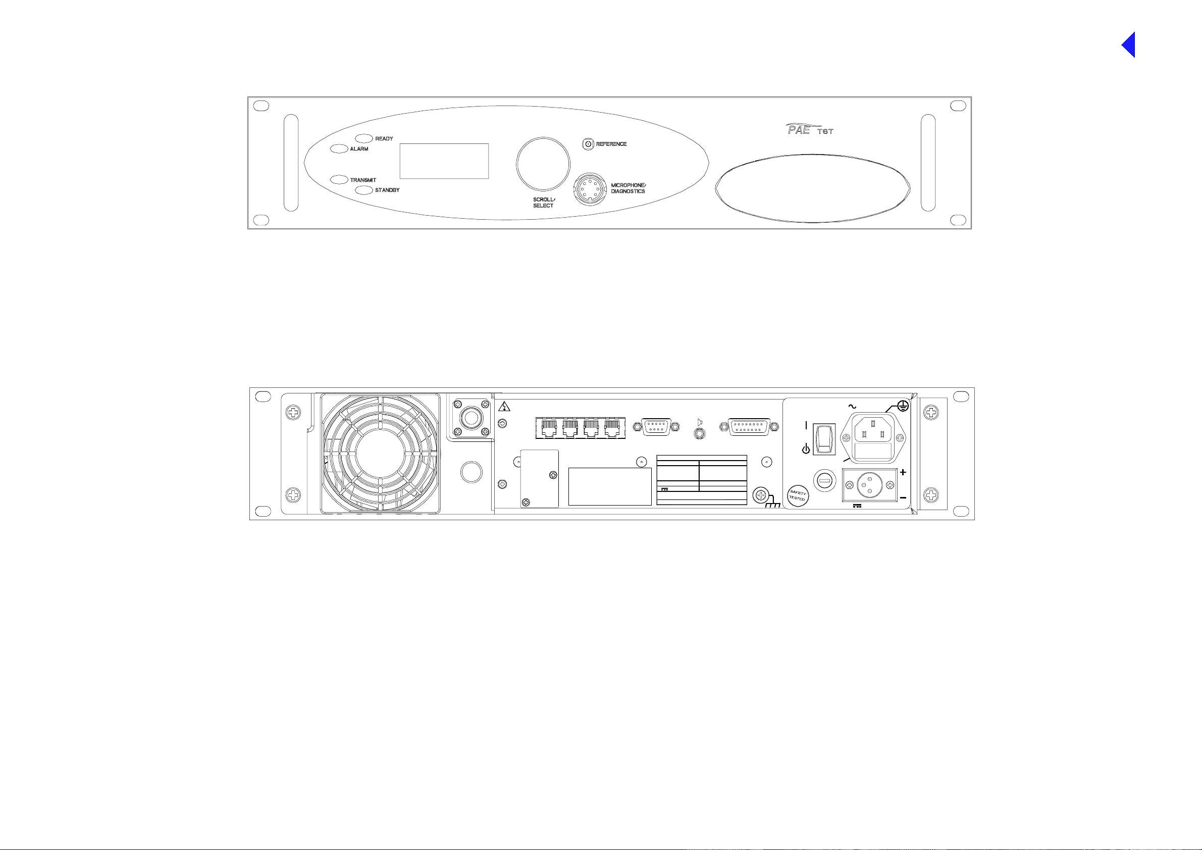
Front View
Back to Transmitter
Main Page
ANTENNA
DANGER HIGH
RF VOLTAGES
CONNECT
ANTENNA
BEFORE
USE
T1/E1 HDLC
MARC
MARC
DATA
AUDIO
Rear V ie w
MARC FACILITIES
RATINGS
AC SUPPLY
48 - 62H z
~ 110 - 240V ( +10%) 4A
POWER 400VA max
DC SUPPLY
21.6 - 32V 10A
SEE INSTALLATION INSTRUCTIONS BEFORE
CONNECTING SUPPLIES
DISCONNECT SUPPLIES WHEN NOT IN USE
FUSE F2
110-240V T4A 250V IEC
110V - 120V T4A 125V UL
FUSE F1
F15A 32V
AC SUPPLY
SUPPLY
FUSE F2
FUSE F1
DC SUPPLY
SA3597
SA3594
Fig 1 T6T Front and Rear Panels
Page 93
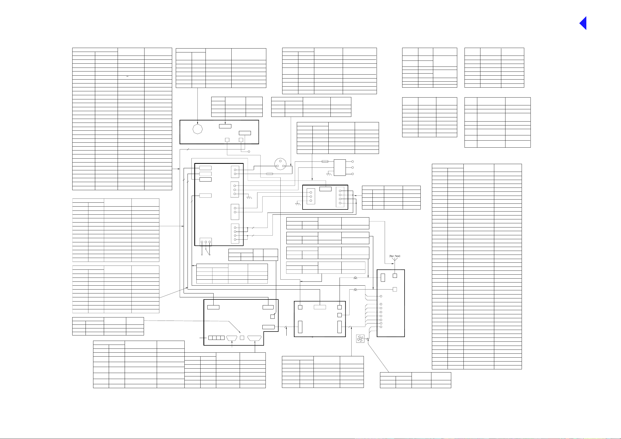
Connections Name Characteristic
Processor
CN4-1
CN4-2
CN4-3
CN4-4
CN4-5
CN4-6
CN4-7
CN4-8
CN4-9
CN4-10
CN4-11
CN4- 12
CN4- 13
CN4-14
CN4-15
CN4-16
CN4-17
CN4-18
CN4- 19
CN4-20
CN4-21
CN4-22
CN4-23
CN4-24
CN4- 25
CN4- 28
CN4-29
CN4-30
CN4-31
CN4-33
CN4-34
Connections
Regulation
CN4-1
CN4-2
CN4-3
CN4-4
CN4-5
CN4-6
CN4-7
CN4-8
CN4-9
CN4-10
CN4-11
CN4-12
CN4-13
CN4-14
Connections
Regulation
CN5-1
CN5-2
CN5-3
CN5-4
CN5-5
CN5-6
CN5-7
CN5-8
CN5-9
CN5-10
Connections Name
Processor
CN8 Tip
CN8 Ring
CN8 Sl eeve Groun d 0 V
CN1-1
CN1-2
CN1-3
CN1-4
CN1-5
CN1-6
CN1-7
CN1-8
CN1-9
CN1- 10
CN1- 11
CN1- 12
CN1- 13
CN1- 14
CN1- 15
CN1-16
CN1-17
CN1-18
CN1-19
CN1-20
CN1-21
CN1-22
CN1-23
CN1-24
CN1-25
CN1-26CN 4-26
CN1-27CN 4-27
CN1-28
CN1-29
CN1-30
CN1-31
CN1-32CN4-32
CN1-33
CN1-34
Processor
CN3-1
CN3-2
CN3-3
CN3-4
CN3-5
CN3-6
CN3-7
CN3-8
CN3-9
CN3-10
CN3-11
CN3-12
CN3-13
CN3-14
PA Control
CN6-1
CN6-2
CN6-3
CN6-4
CN6-5
CN6-6
CN6-7
CN6-8
CN6-9
CN6- 10
External Speaker
1
2
3
Processor
Front Panel
Connections
CN5-1
CN5-2
CN5-3
CN5-4
CN5-575
CN5-6
CN5-7
CN5-8
LED Alarm
LED Ready
LED Standby
LED Tx
LCD RS
LCD R/W
LCD Enable
Data 0
Data 1
Data 2
Data 3
Data 4
Data 5
Data 6
Data 7
LCD Backlight
Transmit Data
+5 V Supply
Receive Data
-5 V Supply
Ground
+15 V Supply
Ground 0 V
LED RX (not used)
Turn +
Turn -
Push
Mic PTT
Ground
Sidetone (Headset Drive) 3 V ac pk-pk
Loudspeaker Amp Drive
Ground
Mic Input
Ground 0V
Name Characteristic
+15 V Supply
+15 V Supply
+5 V Supply
+5 V Supply
Ground
Ground
-15 V Supply
-15 V Supply
ac Detect
dc Detect
V Unreg
V Unreg
Remote on/off
n/c
Name
+15 V Supply
+15 V Supply
+5 V Supply
+5 V Supply
Ground
Ground
-15 V Supply
-15 V Supply
ac Detect
dc Detect
External Speaker Drive
External Speaker Drive 3 Vac pk-pk max
Facilities
1
2
3
4
6
80 V
Open collector (5mA)
Open collector (5mA)
Open collector (5mA)
Open collector (5mA)
TTL
TTL
TTL
TTL
TTL
TTL
TTL
TTL
TTL
TTL
TTL
Open collector (200mA)
RS232
+5 V
RS232
-5 V
0 V
+1 5 V
Open collector (5mA)
5 V pull-up
5 V pull-up
5 V pull-up
0 V=PTT,5 V pull-up=PTT
0 V
2V p-p ma ximu m
0V
1.6V p-p maximum
+15 V
+15 V
+5 V
+5 V
0V
0V
-15 V
-15 V
15V on, 0V off
Open collector
21.6 to 32 V
21.6 to 32 V
0V = off, open collector = on
n/c
Characteristic
+15 V
+15 V
+5 V
+5 V
0V
0V
-15 V
-15 V
n/c
n/c
Characteristic
3 Vac pk-pk max
Ground 0 V
E Bit
PTT
External VSWR
Antenna Change Over
Antenna Change Over
Sque lch Defea t (not used)
Ground
CharacteristicName
TT L pul l-u p act ive low
Grounding output +/- 60V,
100mA max.
TT L pul l-u p act ive low
Grounding output +/- 60V,
100mA max.
Grounding output +/- 6 0V ,
100mA max.
TT L pull-up active low
Connections Name
Front Panel
Mic roph one /
Diagnostics
CN2-1 1 Ground - Microphone 0 V
CN2-2
CN2-3 3
CN2-4 4 Receive Data RS232
CN2-5 5 Sidetone (Headset Drive) 3 Vac pk-pk, 200R
CN2-6
CN2-7 7 G round 0 V
Front Pane l
14
2 Transmit Data RS232
MIC PTT
6 Microphone Input
CN2
Microphone/Diagnostics
34
Power Supply Regulation
10
3
CN7
2
13
(Rear Pa nel)
Connections
Regulator
CN3-1
CN3-2
CN3-3
*
Connections
CN5-9
Facilities
9
10 Inhi bit
11 BIT Interruptive Test
12
13
14
15
Processor
CN5-10
CN5-11
CN5-12
CN5-13
CN5-14
CN5-15
0 V = PTT , 5 V pull-up = not PT T
6k8 input impedance , 5mV sensitiv ity
Connections
Front Panel
CN3-1
CN3-2
CN3-3
CN4
CN5
CN6
CN3
Suppl y
(shown in
off position)
CN3 V Unreg
Heatsink
CN3 CN4
T1/E1
HDLC
A B C D
CN7
Loudspeaker Output
Ground
n/c n/c
CN3
CN4
CN212
CN8
CN9
CN1
RF PA
MARC AUDIO
MARC DATA
CN6
Name
Unregulate d Supply
RSSI (not used)
Ready Output
Tape Output
Reserved
Name
CN5
1 L
2 N
3
E
L
N
1
2
3
4
Connections
Name
-33 V
Ground Supply
MARC
**
EXT
SPKR
CN8
Open collector, 0 V = Ready
Characteristic
Characteristic
7.5V pk-pk Max
0 V
CN1
Reference Frequency
(Front Panel)
2
2
Processor
CN2-1
IF
Characteristic
21.6 to 32 V
n/c
0 V
Facilities
CN5
Characteristic
Fused 300mA 21.6 to 32 V
TT L pull-up active l ow
TT L pull-up active l ow
Potential range 0 V to 10 V
-10 dBm. 100R
n/c
**
Connections
Processor
MARC P ort
CN6-1
CN6-2
CN6-3
CN6-4
CN6-5
CN6-6
CN6-7 7
CN6-8
CN6-9 9
Connections
DC Input Regulati on
Input-1 CN2-2
In put- 2 CN 2-1 Gr oun d Su pply 0 V
Input-3 n/c
3
dc I nput
2
1
(Rear Panel)
CN1-1
RF PA
Char acteri sticName
n/c
CN2
CN1
Processor
50
***
PA Control
CN2-1
CN2-2
CN2-4
CN2-5
CN2-6
PA Control
PA Control
CN5-1
1
2
3
4
5
6
8
dc Input
Connections Name
CN6-1
CN6-2
CN6-4
CN6-5
CN6-6
Power Supply
L
N
E
Connections
PA
Antenna Port
Connections
PA Control
CN4-1
Connections Name Character istic
RF PA
Connections
Front Panel
CN4-1
CN5
CN1
PA Control
Connections Name
RF PA
CN4
CN2
CN7
CN5
CN9
CN12 PA Current De tect (not used) 0.1V per Amp
Name
Ground
Line I n +
Line In -
PTT Input
Unregulated Su pply
Data RX B - Data I n +
Data RX A - Data I n - RS422
Data TX A - Data Out -
Name Characteristic
Fuse d 21.6 to 32 V
n/c
PSURegulation
0 V
PSU OK
PSU OKCN6-3
PSU off
0 V
CN4-3
CN4-1
PSU of f PSU off 0V = 0ff
(Rear Pa nel)
RF Output
Forward Power S ense CN8
Reference Frequency
CN6
PA Temperature
Drive D etect
PA Bias EnableCN2-3
Fan Enable
Reflected Power
Mains IE C
Connector
Filtered/
Fused
1
CN4
2
CN1
3
4
Name C haracteristic
Name C haracteristic
CN3
CN4
CN2
10 mV/°C + 0.5V
0.5 V for +10 dBm
TTL - High for bias on
TT L - High for fan on
50 W = 670 mV
Characteristic
0 V
+20 dBm to -20 dBm 600R
+20 dBm to -20 dBm 600R
0 V o r +10 V to +60 V or
-10 V to -60 V at 6mA
Fused 500mA, 21.6 to 32 V
RS422
RS422Data TX B - Data Out +
RS422
Characteristic
0 V
0 V O K
o/c OK
0 V = on
0 V
L
N
ac Input
E
5 to 5 0 W
17 dBm ± 1 dB
(-30.5 dBc ± 0.9 dB)
1 dBm carrie rRF DriveCN10CN3-1
CharacteristicName
-20 dBm to 0 dBm
6
Fan
Characteristic
Connections
PSU
CN1-1
CN1-2
CN1-3
CN1-4
2
Regulation
CN1-1
CN1-2
CN1-3
CN1-4
PA
Name Char acteristic
Ground Supply
Ground Supply 0 V
V Unreg
V Unreg
CN1
CN10
CN8
CN3
CN2
CN4
CN5
CN7
CN9
CN12
CN6
RF PA
CN6
PA Heatsink
CN7A
CN7A
CN7ACN7A
*
Pin Number1Name
2
3
4
5
6
7
8
CN7B
CN7B
CN7BCN7B
*
Pin Number
1
2
3
4
5
6
7
8
0 V
29 V
29 V
Fan Control
Fan
Ground 0V
Fan
RRING
RTIP
n/c
TRING
TTIP
n/c
n/c
n/c
Name
HDLC Rx A
HDLC R x B
HDLC CL A
HDLC T x B
HDLC T x A
HDLC CL B
Ground
Unregulate d Supply
Characteristic
ANSI T1.403-1995 (T1),
ITU-T: G.703 (E1)
ANSI T1.403-1995 (T1),
ITU-T: G.703 (E1)
Char acteri stic
RS 422
RS 422
RS 422
RS 422
RS 422
RS 422
0V
21.6V to 32V
***
Connections
CN1-1
CN1-2
CN1-3
CN1-4
CN1-5
CN1-6
CN1-8
CN1-9
CN1-10
CN1-11
CN1-12
CN1-13
CN1-15
CN1-16
CN1-17
CN1-18
CN1-19
CN1-20
CN1-21
CN1-22
CN1-23
CN1-24
CN1-25
CN1-26
CN1-27
CN1-28
CN1-29
CN1-30
CN1-31
CN1-32
CN1-33
CN1-34
CN1-35
CN1-36
CN1-37
CN1-38
CN1-39
CN1-40
CN1-41
CN1-42
CN1-43
CN1-44
CN1-45
CN1-46
CN1-47
CN1-48
CN1-49
CN1-50
CharacteristicConnections Name
10V approx. or 26.5V
PA ControlProcessor
CN1-1
CN1-2
CN1-3
CN1-4
CN1-5
CN1-6
CN1-7CN1-7
CN1-8
CN1-9
CN1-10
CN1-11
CN1-12
CN1-13
CN1-15
CN1-16
CN1-17
CN1-18
CN1-19
CN1-20
CN1-21
CN1-22
CN1-23
CN1-24
CN1-25
CN1-26
CN1-27
CN1-28
CN1-29
CN1-30
CN1-31
CN1-32
CN1-33
CN1-34
CN1-35
CN1-36
CN1-37
CN1-38
CN1-39
CN1-40
CN1-41
CN1-42
CN1-43
CN1-44
CN1-45
CN1-46
CN1-47
CN1-48
CN1-49
CN1-50
CN7C
CN7C
CN7CCN7C
*
Pin Number1Name
Data Rx A (Data In -)
Data Rx B (Data In +)
2
n/c
3
4
Data Tx B (Data Out +)
Data Tx A (Data Out -)
5
Remote Supply On/Off
6
Ground
7
Unregulated Su pply
8
CN7D
CN7D
CN7DCN7D
*
Pin Number
Ground
IF AGC (Not used)
Ground
RF AGC (Not used)
Ground
I
Ground
BIT I Monitor
Ground
BIT Q Monitor
Ground
Q
Ground
Tx/Rx Detect
Power Down
Ground
Filter 0
Filter 1
Filter 2
Filter 3
Filter 4
Ground
Synth Load
Data
Clock
Phase Load
Reserved
Tx Key
Auto Level Control
PA Temperature
Reflected Power
PAC Temperature
External VSWR
Narrow/Wide (Not used)
BIT C ontrol 0
BIT C ontrol 1
BIT O pen Loop
BIT S ynth Lock
BIT Loop Correct
BIT V SWR OK
RF PA Bias Disable
Fan Enable
OCXO F itted
Reserved
Step Size (Not used)
TR Detect
V/U Dete ct
BIT Contr ol 2 (Not used)
BIT Contr ol 3 (Not used)
Name
Line In -
1
Line In +
2
Fast Antenna Change Over /
3
PTT
Not used
4
Not used
5
PTT Input
6
7
Ground
Not used
8
Name Characteristic
Char acteri stic
RS 422
RS 422
RS 422
RS 422
0V
21.6V to 32V
Characteristic
+20 dBm to -20 dBm 600R
+20 dBm to -20 dBm 600R
NPN open collector
grounding transistor
+20 dBm to -20 dBm 600R
+20 dBm to -20 dBm 600R
0 V or +10 V to +60 V or
-10 V to -60 V at 6mA
0 V
0 V or +10 V to +60 V or
-10 V to -60 V at 6mA
0 V
0 to 2.5 V
0 V
0 to 2.5 V
0 V
0 to 2.5 V
0 V
±2.5 V
0 V
±2.5 V
0 V
0 to 2.5 V
0 V
0 to 4 V / 0 to 6VFrequency TrimCN1-14 CN1-14
TTL
TT L pull up active low
0 V
TTL
TTL
TTL
TTL
TTL
0 V
TTL
TTL
TTL
TTL
TTL
TTL
0 to 5 V (5 V 3dB back off)
10 mV / °C
0 to 2.5 V
10 mV / °C
TTL
TTL
TTL
TTL
TTL
TTL
TTL
TTL
TTL
TTL - High fan on
TT L - Low OCX O fitted
TTL
TTL
TTL
TTL
TTL
TTL
Back to Transmitter
Main Page
T6S2VHF Tx Interconnection and Wiring
Fig 2 Wiring and Interconnection Diagram
Page 94

Antenna Connecto r
Back to Transmitter
Main Page
Regulation Module
Power Supply
Processor Module
Fan
VHF TX PA Control Module
VHF TX RF PA Module
Tx Module Location
View on underside - Bot t om Cover re m oved
Top view - Top Cover removed
T6 Series 2 VHF Transmitter
Module Location Diagram
Front Panel Module
Fig 3 Modu le Lo c at i on D i agram
Page 95

Back to Transmitter
Main Page
8
N
C
A
P
GA10931
Fig 4 Processor Module - Removal and
Refitting D etail
Page 96

CN8
Brown (L)
Blue (N)
Back to Transmitter
Main Page
CN6
CN7
CN2
CN1
CN3
GA10929
Fig 5 PSU Regulator Module - Removal and
Refitting D etail
Page 97
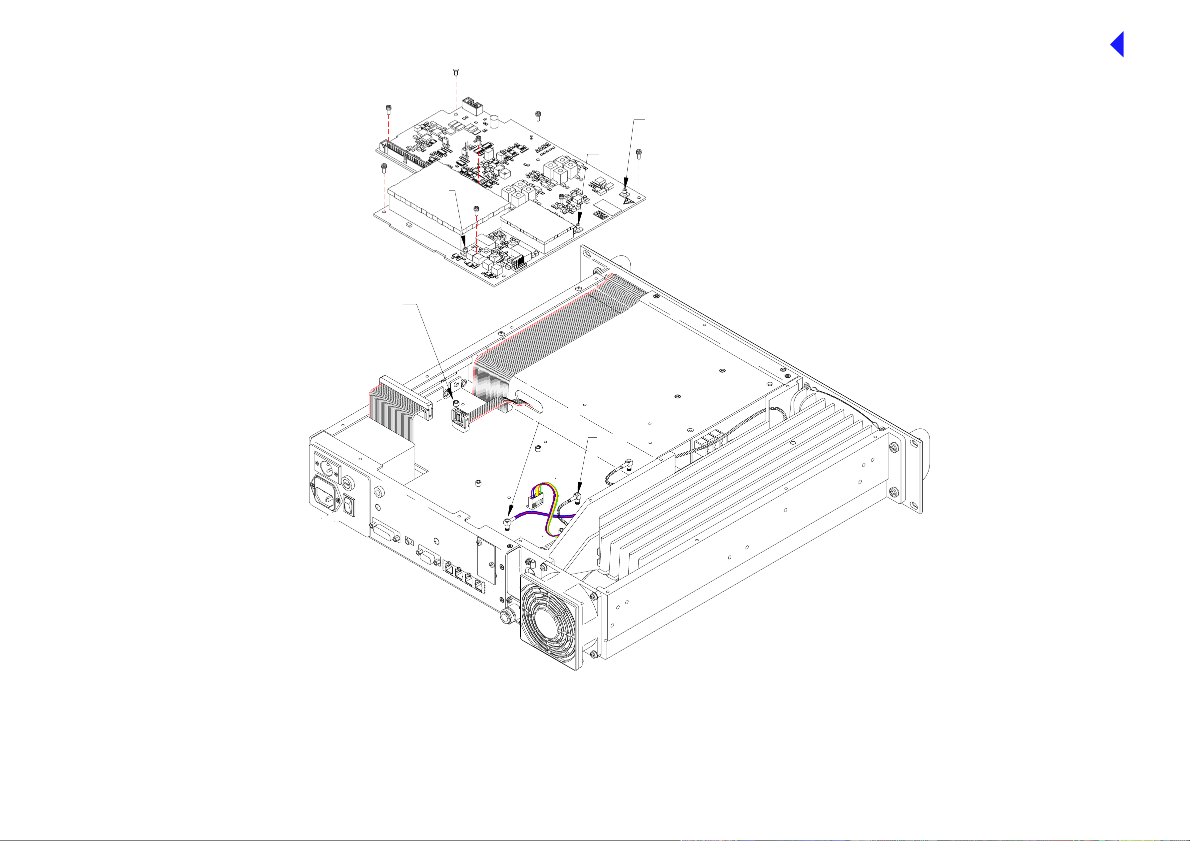
This connector will twist on itself
Back to Transmitter
Main Page
CN3
CN4
CN5
CN5
CN4
3
C
P
Fig 6 PA Control Module - Removal and
Refitting Detail
Page 98

Power Su ppl y
Back to Transmitter
Main Page
GA10928
Fig 7 Power Supply - Removal and
Refitting D etail
Page 99

Back to Transmitter
Main Page
GA10930
Fig 8 PA Module - Removal and
Refitting D etail
Page 100

Back to Transmitter
Main Page
CN5 PA Control
Diagram A
Allen head grub screw
Front panel PCB
Front P anel
Diagram B
GA10944, GA10927
Fig 9 Front Panel Assembly PCB - Removal
and Refitting Detail
 Loading...