

Park DF2000 DSP, DF1400 DSP, DF3200 DSP Owner's Manual

PROFESSIONAL
TWO CHANNEL
SWITCHING POWER AMPLIFIER
DF series with DSP
DF2000DSP
DF3200 DSP
DF1400 DSP
Owner’s Manual
R

ACCESSORIES
1. Power Cord 1pc.
2. Owner’s Manual 1pc.
3. Warranty 1pc.

CAUTION
RISK OF ELECTRIC SHOCK
DO NOT OPEN
AVIS
RISQUE DE CHOC ELECTRIQUE
NE PAS OUVRIR
CAUTION! The amplifier runs on 230V AC voltage. Removing the cover will expose
you to a potentially dangerous voltage! Do not use the unit if the electrical power cord is
frayed or broken.
Power is supplied from 230V AC single-phase grounded 50/60 Hz source!
CAUTION! The amplifier can yield dangerous output voltage! Do not touch the non-
insulated cable parts, connected to the unit in operation!
CAUTION! The high sound pressure level of speaker systems generated by high
output power, delivered by the amplifier, may be hazardous to your hearing. Please,
take adequate safety precautions.
WARNING! The amplifier yields high output power. The manufacturer shall not be held
responsible for any damage to the speakers caused by excessive power from the unit.
WARNING SIGNS:
Important information!
Intended to warn the user about any important applicable information
contained in this Owner’s Manual.
Hazardous voltage inside!
Intended to warn the user about electric shock hazard due to high voltage
inside the product.

GENERAL
DFseries with DSP (DF1400 DSP, DF2000 DSP, DF3200DSP) are modern
amplifiers for professional entertainers, who require maximum performance and sound
quality on a limited budget. Amplifiers are designed for application in
PA systems with high requirements for precise tuning of the parameters, but without the
need for operative change.
Built-in DSP accurately handles the audio signal due to its functions of equalization,
filtering, delay and limiter. Processor has 2 inputs and 2 outputs and provides free signal
routing from any input to any output.
DSP enables users to choose between eight factory preset settings. Setting
presets (operation modes) is performed by DIP switch. Any of presets can be modified
using a computer connected via USB interface (software – SigmaStudio by Analog
Devices, Inc.).
ATTENTION! The DF1400DSP, DF2000DSP and DF3200DSP amplifiers have the
same design and functional features and differ only in the schematics elements, output
power and weight. Unless specified otherwise, the word «amplifier» hereinafter applies to
any of the above models..
To ensure the most advantageous and faultless operation of the amplifier, please,
read this Manual before use.
UNPACKING
The manufacturer’s quality control system provides for careful examination of each
product before it leaves the factory to ensure its flawless appearance. After unpacking,
please, check the unit for any physical damage. In case of damage, please, contact your
local dealer. Keep the shipping carton and all packing material, as you may require them
for reshipment of the unit.
2

DESIGN FEATURES
Physical Design
The amplifier is enclosed in a metal (steel) case of 88 mm (2U) height. The amplifier
is designed to be standard rack-mounted (RACK 19").
Power Supply Unit
Both channel of the amplifier share the same pulse power supply unit.
Power Factor Correction (in DF2000 DSP only)
The amplifier has power supply with Power Factor Correction, which significantly
reduces load to the mains and also reduces noise and distortion in the mains. What is
more important, the amplifier output power is no longer rigorously dependent on the mains
voltage. The amplifier provides full power at the mains voltage from 160V to 250V (with ~ ~
no need to use of external AC voltage stabilizer).
Cooling System
The amplifier features a forced cooling system which is common for both channels.
The amplifier and the power supply unit are cooled with a single fan blowing front to rear.
The cooling system provides for a double-step intensity-cooling rate switching. At a normal
temperature, the fan runs at a low speed, thus generating the least noise possible. When
the amplifier is set to deliver a high output power or when the ambient temperature is
higher than normal, the cooling system may switch the fan to the other (higher) cooling
rate.
Output Stage
The output stage of this digital power amplifier is designed according to Class D
technology to deliver high efficiency and least heat. The high switching rate ensures the
high sound quality comparable with the best analogue amplifiers.
Balanced Inputs
The use of balanced inputs provides for an essential reduction of the environmentinduced hum and noise interference with long input connecting cables.
Line Outputs
The line outputs have a post-DSP signal. The signal parameters are determined by
the selected preset setting. You can change the signal parameters using the USB
interface.
DSP
Built-in DSP accurately handles the audio signal due to its functions of equalization,
filtering, delay and limiter. Processor has 2 inputs and 4 outputs and provides free signal
routing from any input to any output.
DSP enables users to choose between eight factory preset settings. Preset
parameters are listed on the insert in the Owner’s Manual.
Any of presets can be modified, using a computer connected via USB interface
(software – SigmaStudio by Analog Devices, Inc.).
The installation package of the SigmaStudio ver.3.10 software (32-bit and 64-bit
program versions available) and user manual can be downloaded from the site
parkaudio.ua (Download section on the pages of the corresponding amplifiers).
3

Moreover, in the Download section you can find:
SigmaStudio User Manual – user guide on setting built-in amplifers with DSP by
SigmaStudio.
SigmaStudio Video Tutorial – video tutorial about setting amplifers with DSP by
SigmaStudio.
Limiter’s User Manual – recommendations on limiters setting in signal processing
tracts;
Project Templates – SigmaStudio project template for amplifiers with DSP;
DF-series Factory DSP Presets – DSP preset settings description.
Limiter’s Setting Calculations – simple calculator (Excel) to calculate the
parameters of the limiter.
DSP PRESET Switch
The amplifier modes (DSP presets) can be switched by the DIP switch, located on
the rear panel.
Input Level Attenuators
These allow setting the amplifier to the required sensitivity (each channel
individually) which is very helpful when several amplifiers are used to drive different types
of loudspeakers or are used within multi-speaker sound reinforcement systems. The
attenuators are located on the front panel.
Detachable Power Cord
This feature is provided for convenience of transportation and rack mounting.
4

FUNCTIONAL FEATURES
Overload and Short-Circuit Protection
Individual per each channel. This protective system becomes active in case of shortcircuited output or overload caused by reduced load impedance. It disables the output
signal of the respective channel for 0.5 second and then the amplifier gradually resumes
its delivery.
DC Output Protection
The amplifier’s schematics precludes transit of any clicks or noise during the poweron/off transition process. The power source unit is responsible for preventing any DC
damage to loudspeakers. In the event of output DC voltage or any powerful LF
fluctuations, the power source unit goes off and all indicators, including the POWER LED,
go off too.
The amplifier can be restarted in 2 or 3 minutes by de-energizing and re-energizing
the amplifier with the POWER switch. If the DC is an occasional problem (which is unlikely)
the amplifier goes on and resumes its normal functioning. If, otherwise, the DC output
problem persists through the fault of the amplifier, then upon switching, the amplifier goes
on, the POWER amplifier goes on but in a short while the DC output protection system
disables the power supply source.
Thermal Protection
Independent for each channel. In this case upon reaching 85°C, the independent
protection system disables the respective channel of the amplifier. The CLIP LED goes on
and the SIGNAL LED of the affected channel goes off.
As soon as the amplifier cools down, the affected channels gradually regain their
amplification level up to the set value.
Soft Signal Start
During the power-on process, this feature ensures smooth gain from zero to the
maximum level to provide for a smooth rise of the sound level emitted from the loudspeakers.
5
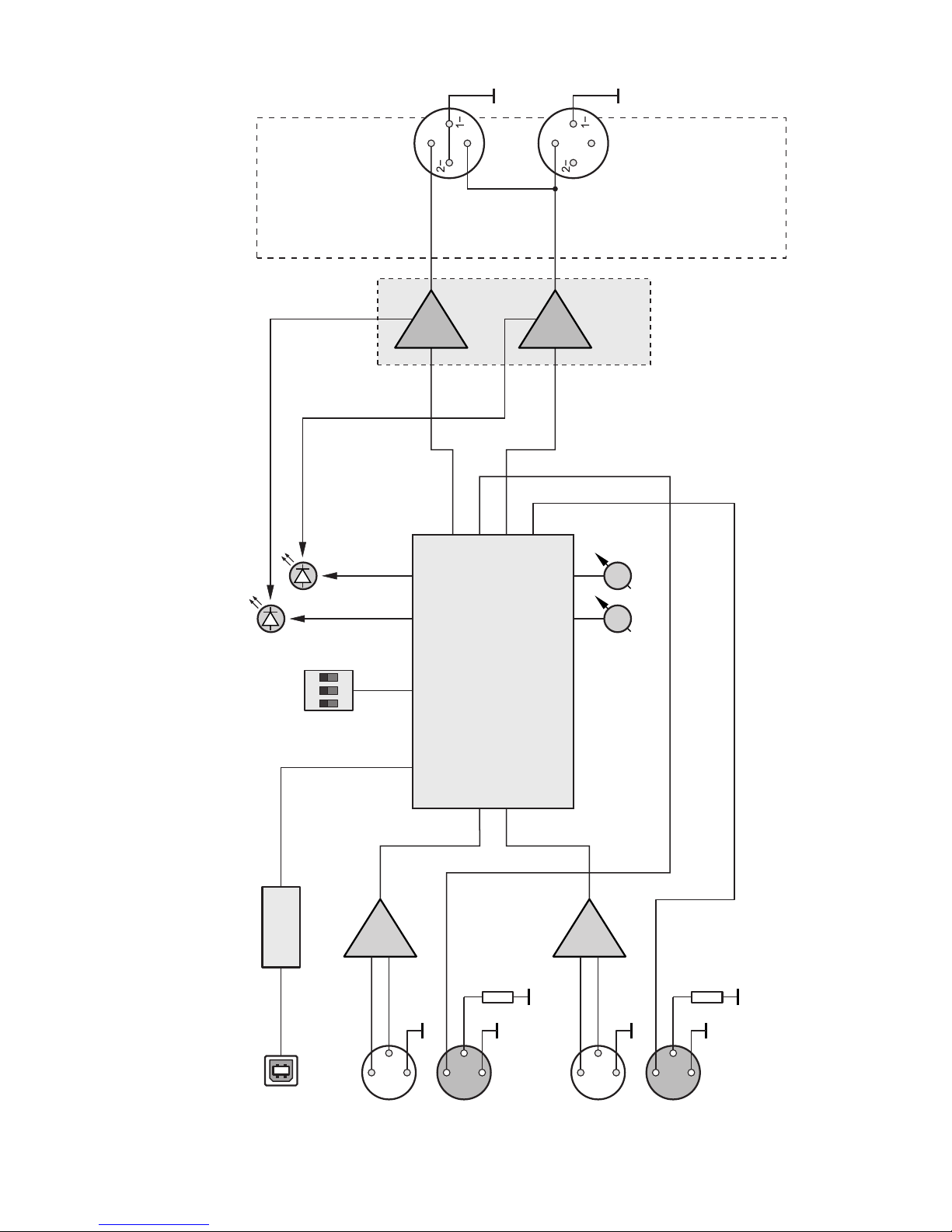
BLOCK DIAGRAM
INPUT CH 1
Power
amplifier
Ch 1
2+
2+
LEVEL
CH1, CH2,
BRIDGE
SPEAKER
OUTPUTS
CH2
DSP
Out 0
In 0
Out 2
Out 1
In 1
Out 3
DSP
PRESET
1
2
3
ON
DIP
Switch
Ch1 Ch2
CLIP
Ch2 LIMIT
Ch1 LIMIT
Ch2
CLIP
Ch1 CLIP
Ch 2
USB Port
USB
Interface
OUTPUT A
( )
POST DSP
INPUT CH 2
OUTPUT B
( )
POST DSP
1+
1+
6
 Loading...