

Page 1
Tools
Required For Assembly
No
2 & No 4 Phillips
Head
Screwdrivers
No
2 Slot
Head
Screwdriver Hammer
Electric Drill (Hammer Drill for
Masonry)
6.5mm
Masonry
Drill
Bit
Pliers
Spirit
elbatsujdAleveL
Spanners
24mm
Socket
Set
19.06.15
ASSEMBLY
INSTRUCTIONS
DOUBLE
ONE PIECE DOOR
WALL BEDS
STREAMLINE 3000
Page 2
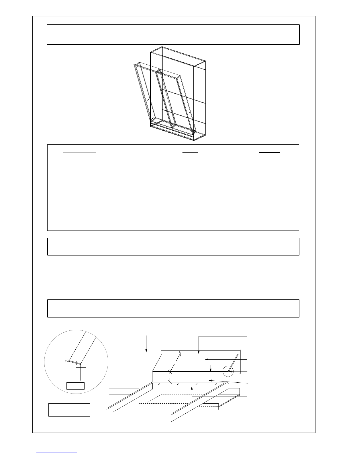
Piano
hinge
Both
edges to
be cut
at
17
degrees
Detail
DIAGRAM
1
17
deg.
angle
to
both
edges
(refer
to
detail
above)
370mm
220mm
Board
is
to
lean
back
against
the
back
rail
Pillowcatch
Head
Board
with 4 x
holes
Bolt
thru
back
of
pillowcatch
so
that
the
nut
is
on
the
inside
of
the
frame
Piano
Hinge
Cupboard
1.
Panels
(Double)
1 x Top
1 x Top
Back
Rail
1 x Back
Rail
1 x Front
Skirting
1 x Bottom
1 x Right
Hand
End
1 x Left
Hand
End
1 x Door
1 x Left
Hand
Frame
Rail
1 x Right
Hand
Frame
Rail
2 x Mid
Frame
Rail
1 x Top
Frame
Rail
1 x Bottom
Frame
Rail
2
x
3mm
Packers
Panel
#
1
2
3
4
5
6
7
8
9
10
11,
12
13
14
15,
16
Size
(mm)
1460 x 446 x 16
1460 x 250 x 16
1460 x 570 x
16
1460 x 100 x 16
1460 x 439 x
16
2100 x 480 x 16
2100 x 480 x 16
1996 x 1456 x 16*
1902 x 160 x 16
1902 x 160 x 16
1870 x 160 x 16
1364 x 160 x 16
1364 x 160 x 16
1800 x 30 x 16
This
is
the
recommended
cabinet
construction
method
to
ensure
the
mechanism
operates
correctly.
Variations
of
construction
should
be
checked
with
Pardo.
16
or
18mm
thick
particleboard
doors
are
recommended.
Mattress
size
1400 x 1900 x 250D
MAXIMUM
depth
Door + Mattress
58
kgs
MAXIMUM
weight
Cabinet
Components
Pillowcatch
Cabinet
Construction
10.
13.
11.
12.
14.
1.
2.
6.
3.
5.
4.
8.
9.
7.
*If door is produced in 2 x pieces additional structural support is required. Refer to detail H.
Page 3

2 x
Counter
Balance
Mechanism
2 x Cabinet Angle Brackets
Bolts
/ Nuts / Screws - Various
2 x Mounting Brackets
2 x
Bed
Straps
28 Slats
56 Slat Cup Holders
1 x
Manual
Foot
64 x Cam
Bolts
10 x Green
Wall
Plugs
64 x Fix
Cams
2 x Handles
1 x Piano
Hinge
15 x Large
Trim
Caps
2.
Cabinet
Hardware
Mechanism
Components
4 x Nut,
Bolt
and
Double
Washer
setup
Page 4
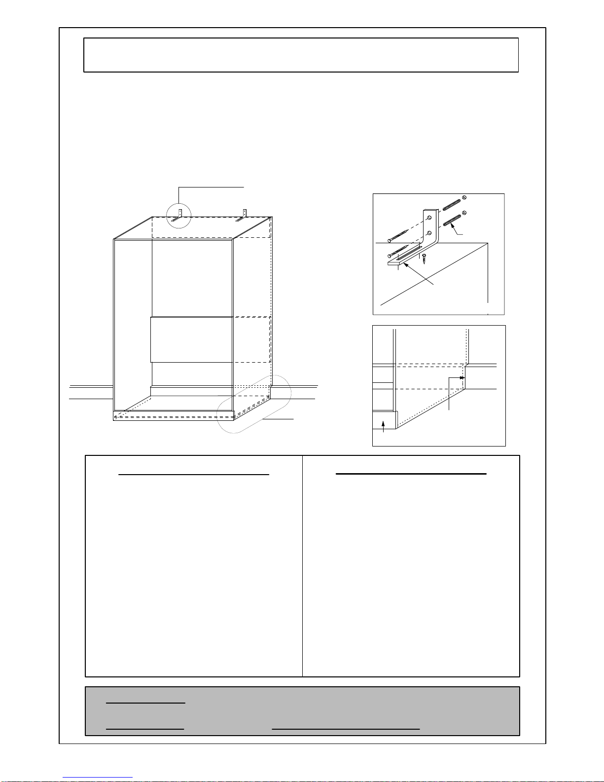
Skirting
Board
Wall
Cut
skirting recess
before
pushing cabinet
against
the
wall
End
Panel
Front
Panel
Base
Panel
DETAIL
B
Fastening
with
angle
brackets
DETAIL
A
Wall
plugs
Refer
to
detail
B
Refer
to
detail
A
3.
Step1 - Fixing
Cabinet
To
Wall
*
Lay
cabinet
face
down
with
bottom
facing
the
wall.
* To
ensure
the cabinet is flush against the wall when upright,
it
may
be
necessary
to
cut a larger recess
into
bottom
of
left
and
right hand
end
of cabinet.
*
Lift
cabinet
at
top,
pushing
towards
wall,
being
careful
to
have
sufficient
ceiling
clearance.
*
Place
cabinet
into
position
against
the
wall
and,
using a spirit
level
against
either
the
right
or
left
hand
end
and
the
top,
find
the
correct
vertical
and
horizontal
position.
Mark
this
position
on
the
wall
with a pencil.
PLEASE
NOTE
As
there is a lot
of tension
in
the
Wallbed when
in
the
open
position,
it
is
very
important
that
the
cabinet is
securely
fixed to
the
wall.
*
Locate
wall
studs
and
mark
clearly
with
pencil.
*
Sit
angle
brackets
in
cabinet
top,
flush
with
top
and
back
edge
and
against
the
wall
studs.
Ensure
that
the
twin
hole
side
of
bracket
is
against
the
wall.
*
Fix
angle
brackets
through
wall
into
studs
using
65mm
screws
.
*
Ensure
cabinet
is
in
correct
vertical
position.
Fix
bottom
of
brackets
into
cabinet
top
using
16mm
screws.
FASTENING
OPTIONS
1
(for
gyprock,
fibro
or timber walls)
FASTENING
OPTIONS
2
*
Ensure
cabinet
is
in
correct
vertical
position.
*
With a pencil
or
nail,
mark
the
wall
through
the
predrilled
holes
in
the
top
back
rail
and
the
bottom
back
rail.
*
Move
cabinet
aside.
Using a 6.5mm
masonry
bit,
drill
60mm
deep
holes
into
wall
and
insert
wall
plugs
supplied.
*
Move
cabinet
back
into
place
against
wall.
*
Fix
top
back
rail
to
wall
through
predrilled
holes
using
65mm
screws.
put
on
cover
caps.
(for
brick/masonry
walls)
*
Fix
bottom
back
rail
to
wall.
Countersink
screws
to avoid
pillow
catch
scraping
on
them.
*
Fix
bottom
back
rail
to
wall.
Countersink
screws
to avoid
pillow
catch
scraping
on
them.
Page 5
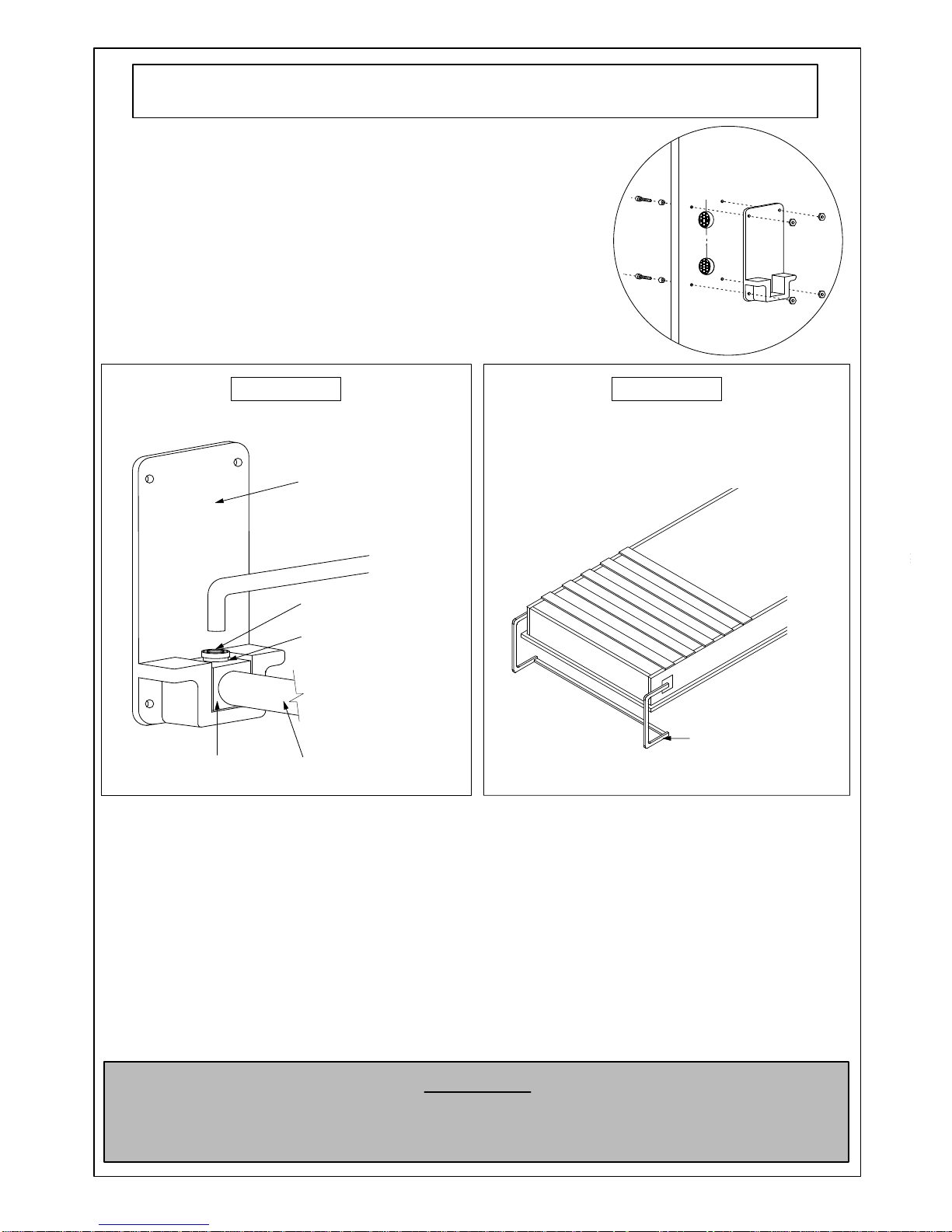
DETAIL
C
SITTING
PIVOT
BLOCK
INTO
MOUNTING
BRACKETS
DIAGRAM
2
Mounting
Bracket
Leave
Levelling
Screw
5mm clearance
for
later
adjustment
Levelling
Screw
Pivot
Block
Counter
Balance
Mechanism
DIAGRAM
3
Manual
Foot
Step2
- Wall
Bed
mechanism
Assembly / Installation
* Bolt
bed
frame
mounting
brackets
to
left
and
right
ends
through
predrilled
holes
using
sleeves
and
bolts
provided.
(DETAIL
C)
* Bolt
left
and
right
hand
counter
balance
mechanisms
to
door
bed
frame.
*
Prior
to
fitting
bed
frame
into
cabinet,
be
sure
leveling
screws
are
protruding
2-3mm
out
of - the
bottom
of
the
block
(for
later
adjustment).
Sit
pivot
block
into
mounting
brackets
(Diagram
2).
When
complete,
leave
bed
frame
vertical
in
cabinet.
* Fit
manual
foot
to
top
of
door
bed
frame
(Diagram
3).
Note:
Door
is
now
ready
to
lift
upwards.
As
there
is
no
tension
on
the
mechanism,
the
doors
are
very
heavy.
(Ensuring
counter
balances
are
to
inside
of
door
bed
frame).
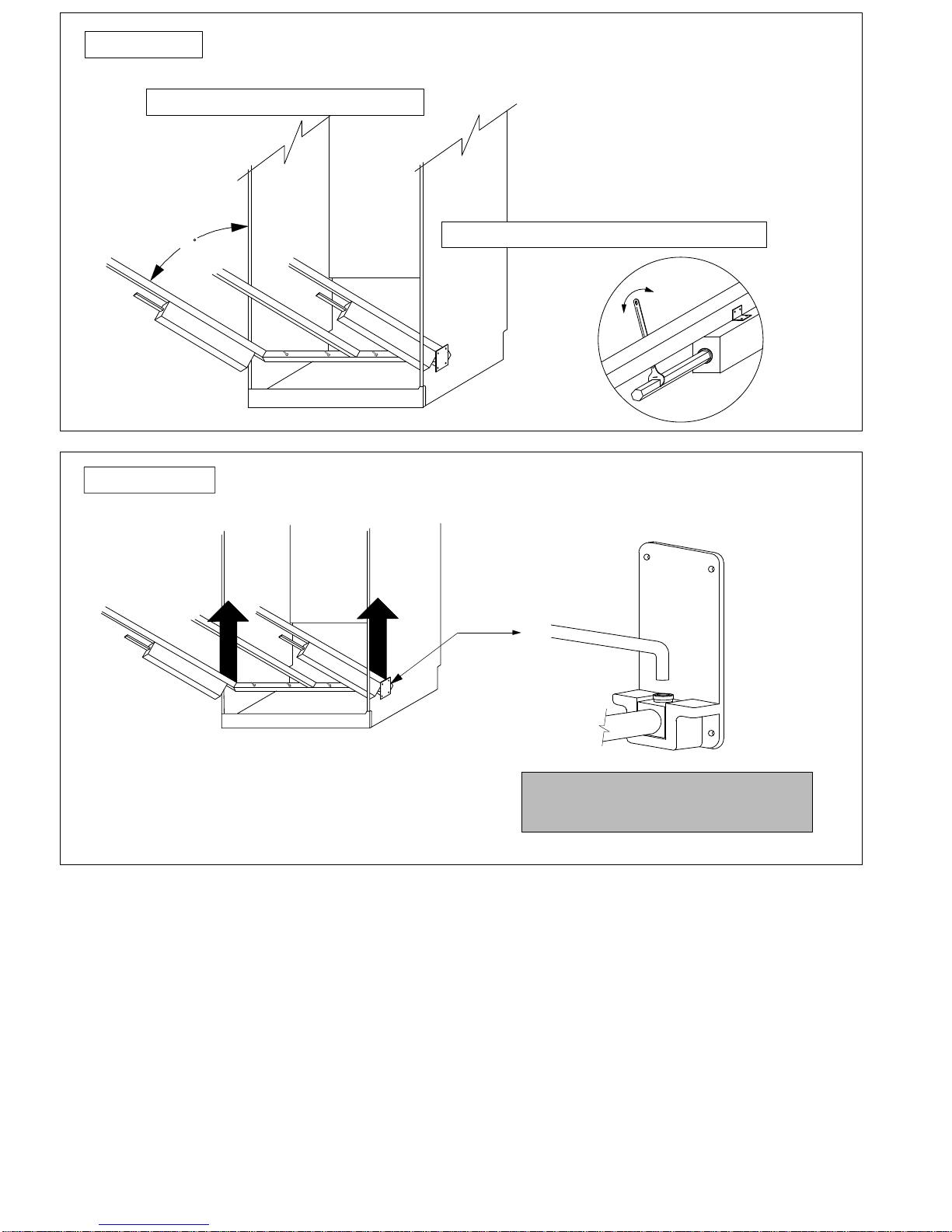
* With
one
person
each
side
of
the
bed,
lift
door
up
to
within
30º
of
closing
(Diagram
4).
* With
a large
24mm socket
turn
tension
handle
clockwise
on
counter
balance
mechanisms
to
adjust
tension.
(Approximately
30
quarter
turns
would
adjust
tension
sufficiently
for a medium
weight
mattress.)
* Test
by lowering
the
cabinet
door
to
floor
and
up
again.
The
correct
tension
is
achieved
when
the
bed
frame
and
doors
lift
slightly
off
the
floor
without
the
weight
of a mattress.
* If
Headboard
and
pillowcatch
are
being
used, hinge
them
together
using
piano
hinge.
* Bolt
Headboard
to
head
of
bed
door
frame.
* Attach
handles
to
door
(handles
not
supplied).
* Attach
bed
straps
to
sides
of
bed
frame
by
sliding
ends
through
sewn
loops
over
frame
edge,
approximately
300mm
from
head
and
foot
of
bed
frame,
and
tighten
until
secure.
* Slide
mattress
onto
bed
frame
and
secure
with
bed
straps.
* Close
doors
and
again
ensure
that
they
align
with
cabinet.
Final
adjustment
may
be
neccessary
and
can
be
done
by
turning
leveling
screws
in
mounting
block
whilst
the
bed
is
open
at
30º.
(Diagram
5)
WARNING
When
operating
the
Wallbed
mechanism
the
bed frame
must
be carefully
lowered
all
the
way
to
the
floor
and
not left to
drop
freely.
If
the
bed frame is lowered
without the
weight
of
a mattress
it
may
spring
back causing
injury.
4.
Page 6
DIAGRAM
4
DIAGRAM
5
5.
ADJUST
TENSION
COUNTER
BALANCE
MECHANISMS
Turn
tension
handles
clockwise
to
increase
tension
ADJUSTING LEVELLING SCREWS
Final
adjustment
of
doors
may
be
made
by
adjusting
levelling
screws
in
mounting
block
whilst
bed
is
open
at
30
degrees
Lift
doors up
to
within
30
degrees
of
closing
30
_
+
Page 7
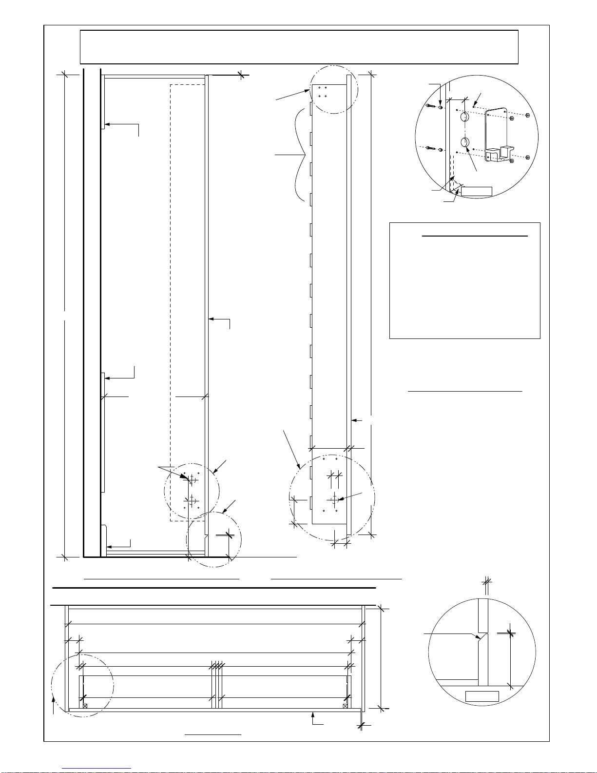
NOTE:
CABINET
CONSTRUCTION
THIS
IS
THE
RECOMMENDED
CABINET
CONSTRUCTION
METHOD
TO
ENSURE
THE
MECHANISM
OPERATES
CORRECTLY.
VARIATIONS OF
CONSTRUCTION
SHOULD
BE
CHECKED
WITH
PARDO
PRIOR
TO
CHANGES.
16
OR
18MM
THICK
PARTICLEBOARD
DOORS
ARE
RECOMMENDED.
Carcass
Side
Elevation
n.t.s
Plan
n.t.s.
Door
Side
Elevation
n.t.s
Min
446mm
For
250mm
thick
mattress
2100mm
2mm
260
96
Wall
Wall
Floor
Line
446mm
MIN.
Refer
to
detail
D
Top
Rail
Door
Middle
Rail
Allow
for
existing
skirting
if
any
Door
16 16
Refer
to
detail F in
installation
instructions
35
1
27
56
Ø
35
Refer
to
detail
E
1460
1996
Door
35
diam.
pivot
hole
through
board
160
16
3
661
3
661
DOUBLE
BED
658
658
100
2
28 slats & caps
provided
to
be
fixed
to
top
of
this
face
1400
16 16
14
30
30
2
35mm
dia. x 11mm
7mm
dia. thru
hole
DETAIL D
73mm
Door
As
Dotted
Skirting
As
Dotted
DETAIL
E
100
45 degree
angle
chamfer
2
4
12.5mm dia. x 8mm
deep
counterbore
to
external
face
of
7mm
dia. thru
holes
Carcass
Construction - Double
Manual
Foot
Wall
Bed
Mechanism
Refer
to
detail H
Refer
to
detail G
6.
Page 8
28
DOOR
1400
35
160
DETAIL F
N.T.S
Carcass Construction - Double
Manual
Foot
Wall
Bed
Mechanism
PLASTIC
CUP
(SLAT
HOLDER)
608
DOOR
160
32
62
SIDE
7mm
DIA.
THROUGH
HOLES
32
60
64
7
1996
SCREW
POINTS
FOR
FOOT / LEG
DETAILS G & H
N.T.S
1215
1368
1456
79
64
48
48
16
3
7.
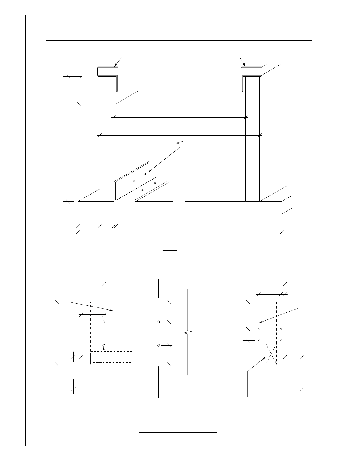
Add full width 70MM x 45MM
timber structural support if door is
produced in 2 x pieces.
CONTINUOUS ANGLE
ALLROUND TO FIX
BASE TO DOOR
 Loading...