

Mavic Parachute Manual
General Safety Instructions
System Package
Installation
Ports & Switches
System Operation
System Removal
Deployment
Repacking
System Status and Troubleshooting
Other Specifications
Compliance Information
4
6
7
20
21
26
31
32
45
46
47
Table of Contents
Important Notice
Copyright © 2019 ParaZero Drone Safety Systems. All rights reserved.
This document and the information contained herein are proprietary and
commercially confidential to ParaZero Ltd. Any use, disclosure, reproduction or
copy by any method of this document or parts thereof is not allowed, except by
the prior written authorization of ParaZero, and then only to the extent authorized.

3
Congratulations on your purchase of the SafeAir Mavic
Safety System!
This manual explains how the SafeAir Mavic system works and
how to properly operate the system on the ground and in the air.
Be sure to take the time to read this manual carefully in order to
increase your safety and the safety of those around you.
The SafeAir Mavic system is a smart-parachute system that
deploys autonomously after detecting a critical failure in your drone.
The parachute slows the descent rate of your drone and reduces the
kinetic energy upon impact.
Note – Using the SafeAir Mavic System does not eliminate all risk
of drone operation. Please fly responsibly and in accordance with
the rules and regulations defined by authorities in the area where
you are operating.
Visit the ParaZero website (www.parazero.com) on a regular basis
for the latest information and updates.

4
General
ParaZero’s SafeAir Mavic is a low altitude, autonomous
parachute-based safety system.
The SafeAir Mavic System is compatible with Mavic Pro, Mavic 2
Pro, Mavic 2 Zoom and Mavic 2 Enterprise series (without modular
accessories).
The average measured descent rate of the Phantom with an open
parachute is 3.7 meters per second (12.1 feet per second).
Main Features
- Unique parachute deployment system that opens in a fraction of a
second, even at zero speed.
- Autonomous emergency identification and activation capabilities.
- Electro-mechanic flight termination system.
- Access data logs from black box via the desktop application.
5
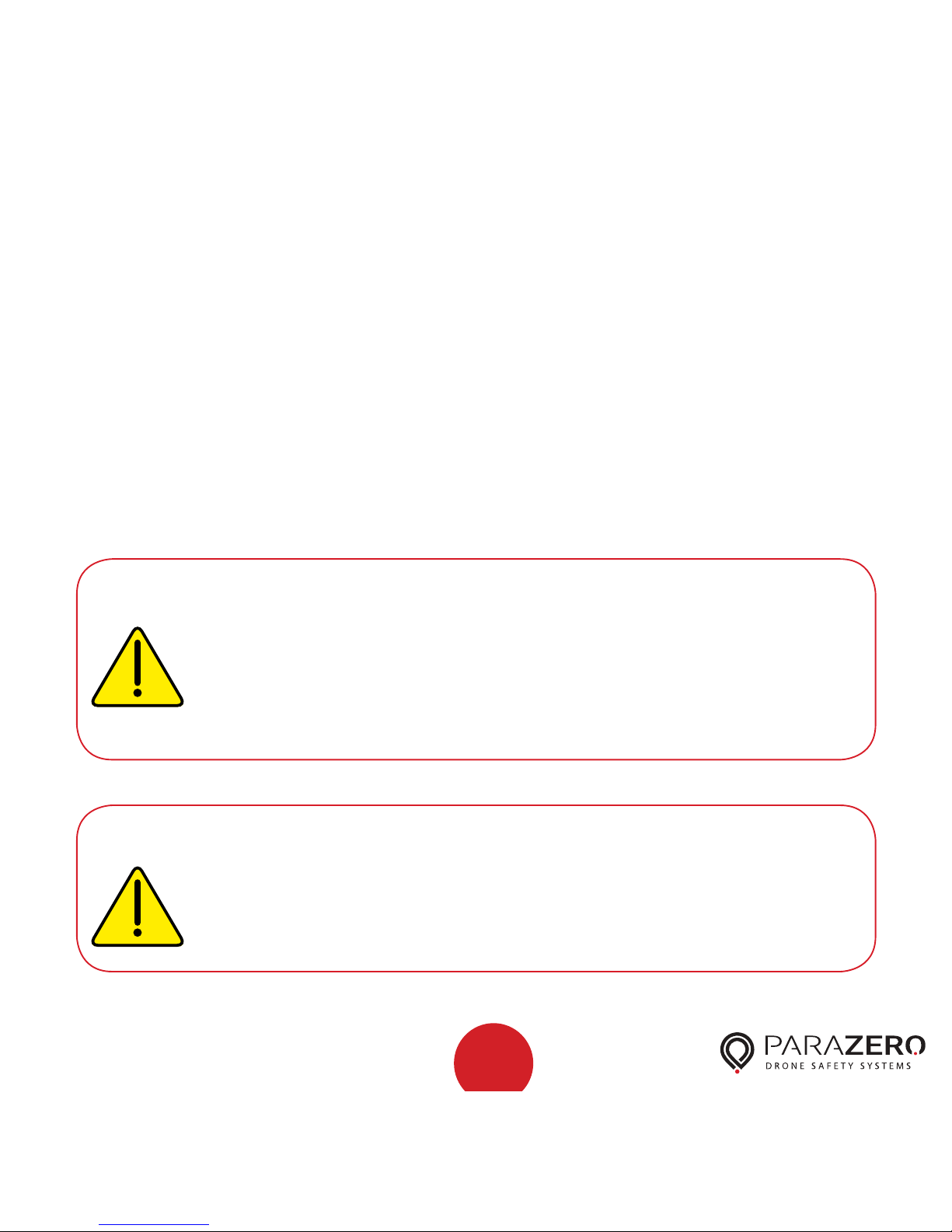
Warning
Caution
Do not move the drone or system while the system is
armed (green LED).
An angle breach may cause the system to deploy.
The parachute and cover will be projected at high speed
and may cause injuries.
Turn the system off immediately after landing.
Using the SafeAir Mavic System is not recommended
in Sport mode.
Safety Instructions
The ParaZero SafeAir Mavic is a drone safety system, designed to
deploy instantaneously by using a powerful spring-based mechanism.
Be careful not to lean against, press or drop the system.
It is imperative to perform system updates on a regular basis through the
desktop application. The current version number is found on the product
webpage: parazero.com/mavic under the software tab. A new device must
be updated before first flight.
6
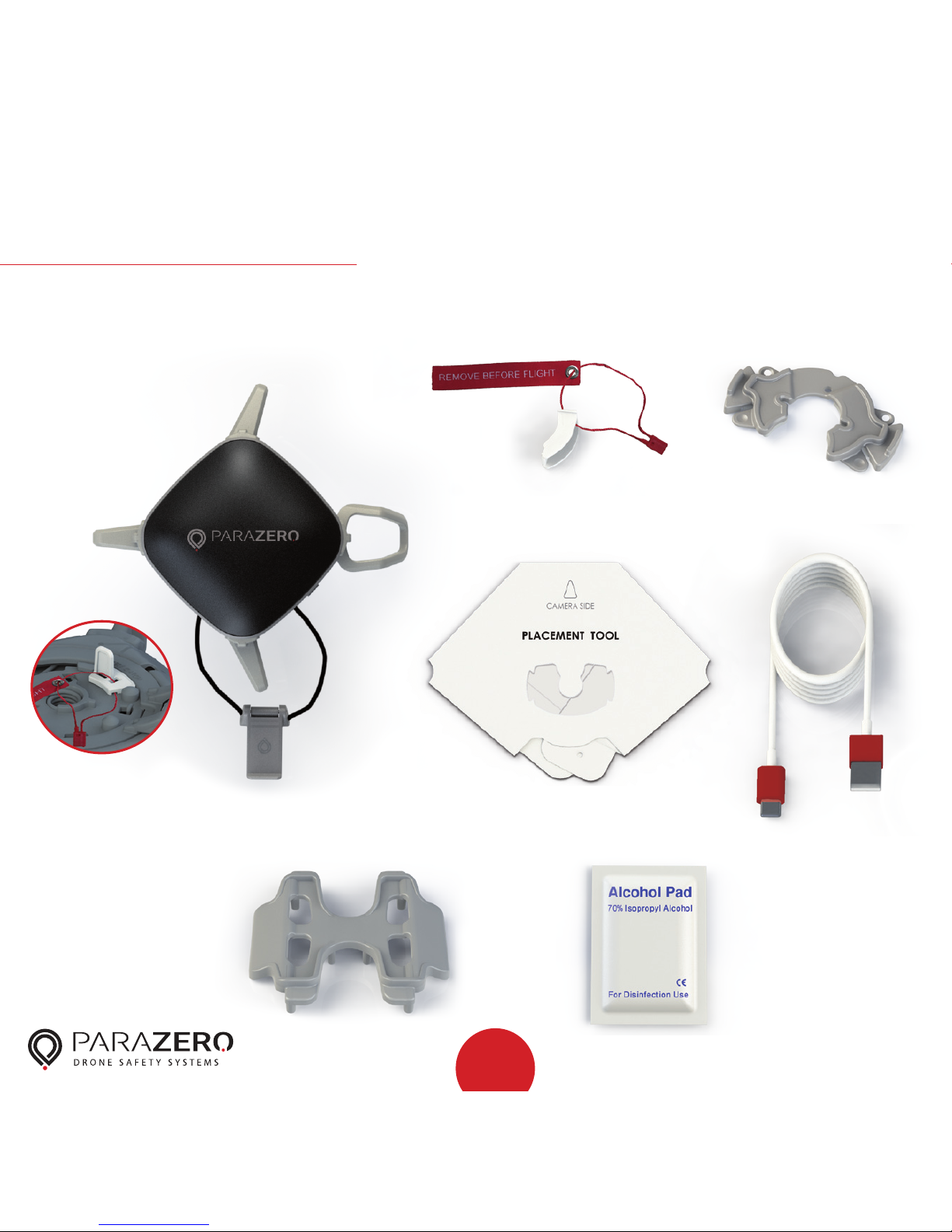
System Package
includes the following parts:
B. Safety insert
C. Placement stamp x3
E. USB-C cable
D. Placement tool
F. Mavic Pro adaptor G. Alcohol pad
A. SafeAir Mavic System
and connected safety catch
7
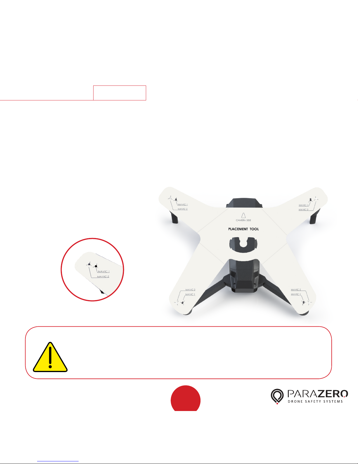
Step
Installation
Place the drone with the battery facing towards you
and unfold its arms, but don’t attach the propellers yet.
Unfold the placement tool and place it on the drone,
so that the camera side arrow is placed above the camera
and the motors’ pins are inserted into the marked holes.
Use the “Mavic 1”
holes for Mavic Pro
and “Mavic 2” holes for
all the rest.
1
Follow installation instructions carefully.
Systems that are not installed correctly may
interfere with the spinning rotors
Caution
Mavic 2
8
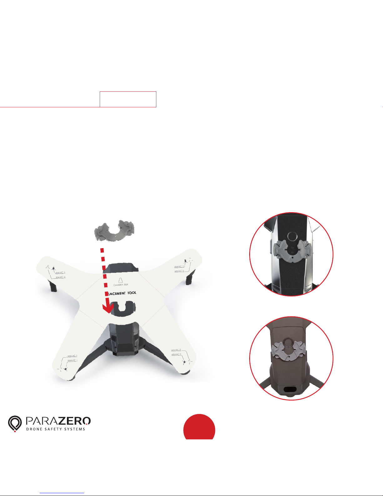
Step
Installation
Clean the area of the hole in the placement tool using the
alcohol pad, remove the sticker cover from the placement
stamp and stick it, by placing it carefully through the hole
in the placement tool.
Remove the placement tool and verify that the placement
stamp is still securely in place.
2
Mavic 2
Mavic 1
9
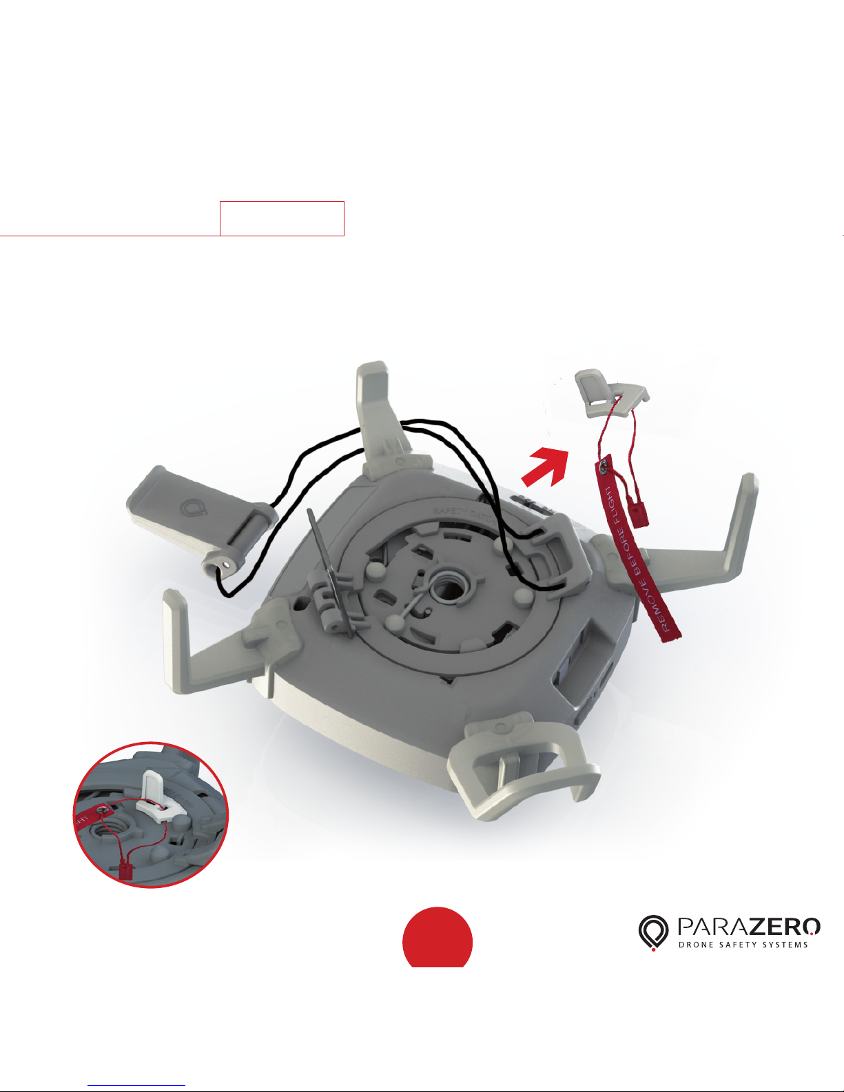
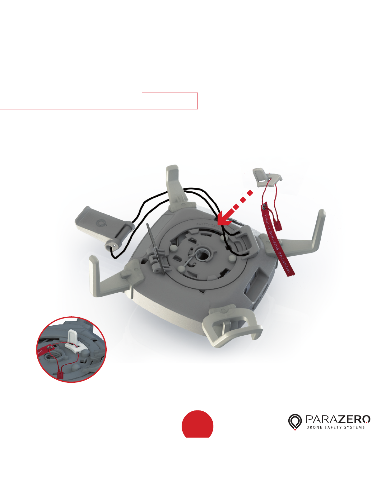
Step
Installation
Remove the safety catch from the bottom of the system
and store it in a safe place for reuse during transport.
3
10
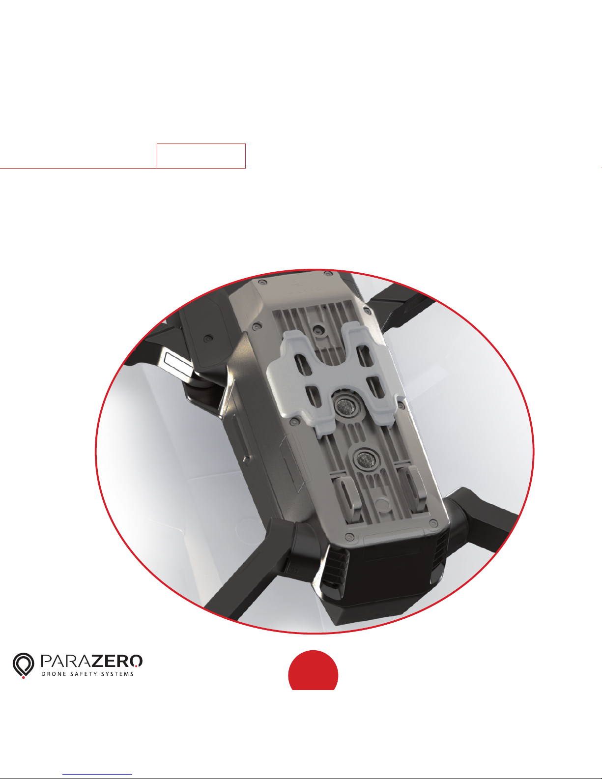
Step
Installation
4
For Mavic Pro – remove the sticker cover from the Mavic
Pro adaptor and connect it on the bottom of the drone as
shown in the illustration.
11
Step
Installation
5
Preflight note: Turn the Mavic on now, as the SafeAir
Mavic is placed on top of the power button.
Place the harness cord under the center of the drone
with the SafeAir Mavic System placed upside-down to
the left of the drone, while the string holder is adjacent
to the drone.
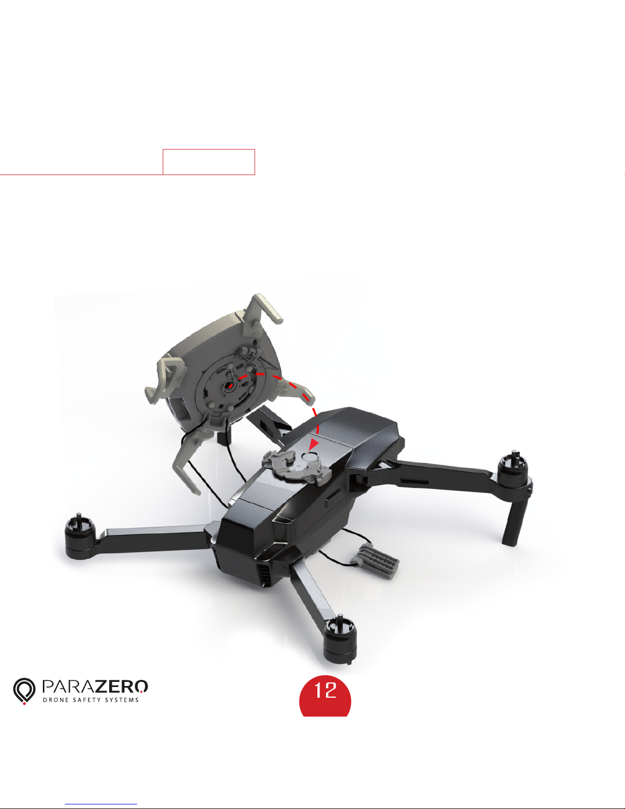
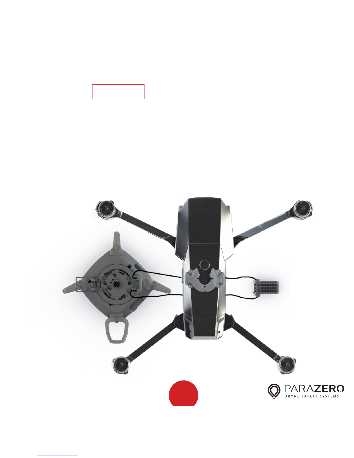
12
Step
Installation
Slide the metal hook away from the base and place the
SafeAir Mavic System by matching the three plugs at the
bottom of the system inside the corresponding sockets of
the placement stamp, (See close-up on the next page).
6
13
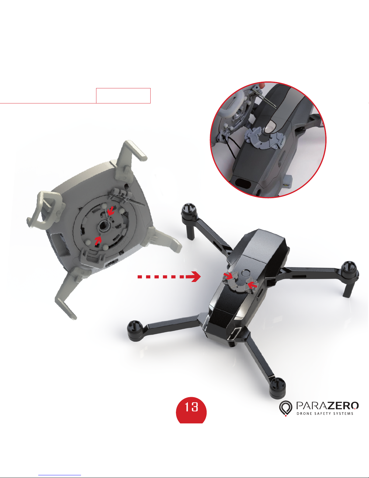
Step
Installation
Match plugs to sockets.
7

14
Step
Installation
Hang the harness on the metal hook and lock the handle
upwards. Watch your fingers while doing so.
8

15
Step
Installation
9
Position the string at the bottom part of the drone as
shown in the illustration to avoid sensors interference.
Mavic 2
Mavic 1

16
Step
Installation
To verify that the harness cord is tight enough, hold the
SafeAir Mavic System, lift it together with the drone and
swing gently. The system and drone should move as one
unit without movement between them. If the harness cord
is not tight enough, repeat the last step while placing the
harness in a higher position.
10

17
Step
Installation
11
Connect the four rotors and verify that they are able to
spin freely without any contact with the SafeAir Mavic
System.

18
Ports & Switches
LED
USB-C
port
System
button
Power switch

System Operation
19
Step
Verify that the batteries are charged before each flight. To
charge the SafeAir’s battery, use the USB-C port.
The minimum charging time before first flight is one hour.
Caution
Batteries that are not fully charged may not
be able to operate towards the end of a long
flight. Be sure to charge your system for at
least 20 minutes before each flight.
1

System Operation
20
Step
Prior to takeoff, verify that the system is placed firmly in
the center of the drone and that the drone’s propellers can
spin freely without touching the system.
2

System Operation
21
Step
To activate the system, verify that the system is on a level
surface and turn the power switch to the ON position.
If it is already ON, turn it OFF and then ON again.
A starting sequence initiates, and the LED turns green and
then yellow for about 20 seconds.
If the yellow LED is flashing, then the system is not on a
level surface. After the system is on and ready in Standby
mode, a blue LED appears.
3

System Operation
22
Step
The system is now ready for flight. After first installation
and when required, perform Mavic compass calibration.
The system autonomously detects takeoff, switches to
Armed mode and the LED turns green.
4

System Operation
23
Step
After landing, the system autonomously disarms and the
LED turns blue a few seconds after rotors stop.
Turn off the rotors and switch the power switch to the
OFF position before moving the drone.
5
Warning As a precaution, always turn the system off
before moving it. Failure to do so could
initiate system deployment.
Inspect your system. Verify that the system is
not damaged and that the rotor stoppers
are intact.

24
Step
System Removal
Unlock the harness by lowering the handle and unhook
the harness from the metal hook.
1
Warning
Verify that the SafeAir Mavic System is off
before removing it from the drone.
25
Step
System Removal
Remove the system from the drone. Insert the safety catch
and store the system in a dry and clean place for reuse.
2

26
Deployment
The SafeAir Mavic includes an Autonomous Triggering
System (ATS) that identifies critical failures and triggers
the system autonomously. Should an emergency situation
occur, the system deploys the parachute and stops
the rotors.
The system can only deploy when it is in Armed mode
(green LED). Following a deployment, the LED turns red.
To switch to Standby mode, reset the system by turning
the power switch OFF and then ON again. The LED
should turn blue after approximately 20 seconds.

27
Installing
After the system has deployed, make sure to
turn the power switch to the OFF position.
Inspect your system to make sure that
the parachute is not damaged, that rotor
stoppers are intact and that the general
condition is good. Ensure that you have all
the parts listed in Step 1, and then follow
the steps described in this chapter.
Important – The SafeAir Mavic System withstands significant
force during deployment. Systems that have been deployed
five times must not be repacked and reused, and should be
replaced.
Repacking
Caution
For professional SafeAir Mavic Systems that
comply with ASTM F3322-18 and are intended
for flight over people, parachutes must be packed
and repacked by ParaZero (or by an entity that
has been certified by ParaZero). For shipping
instructions to ParaZero, contact the retailer from
which you purchased the system or email ParaZero
Support at support@parazero.com.

28
Step
Repacking
1
Place all system components in front of you on a clean,
dry surface.
A. Main canister and
parachute
C. Top cover
D. Inner stage
B. Safety insert
F. Safety catch
E. Parachute

29
Step
Repacking
2
45
While holding the main canister upside down, rotate the
base unit clockwise by 45° until the base is held in
its new position.
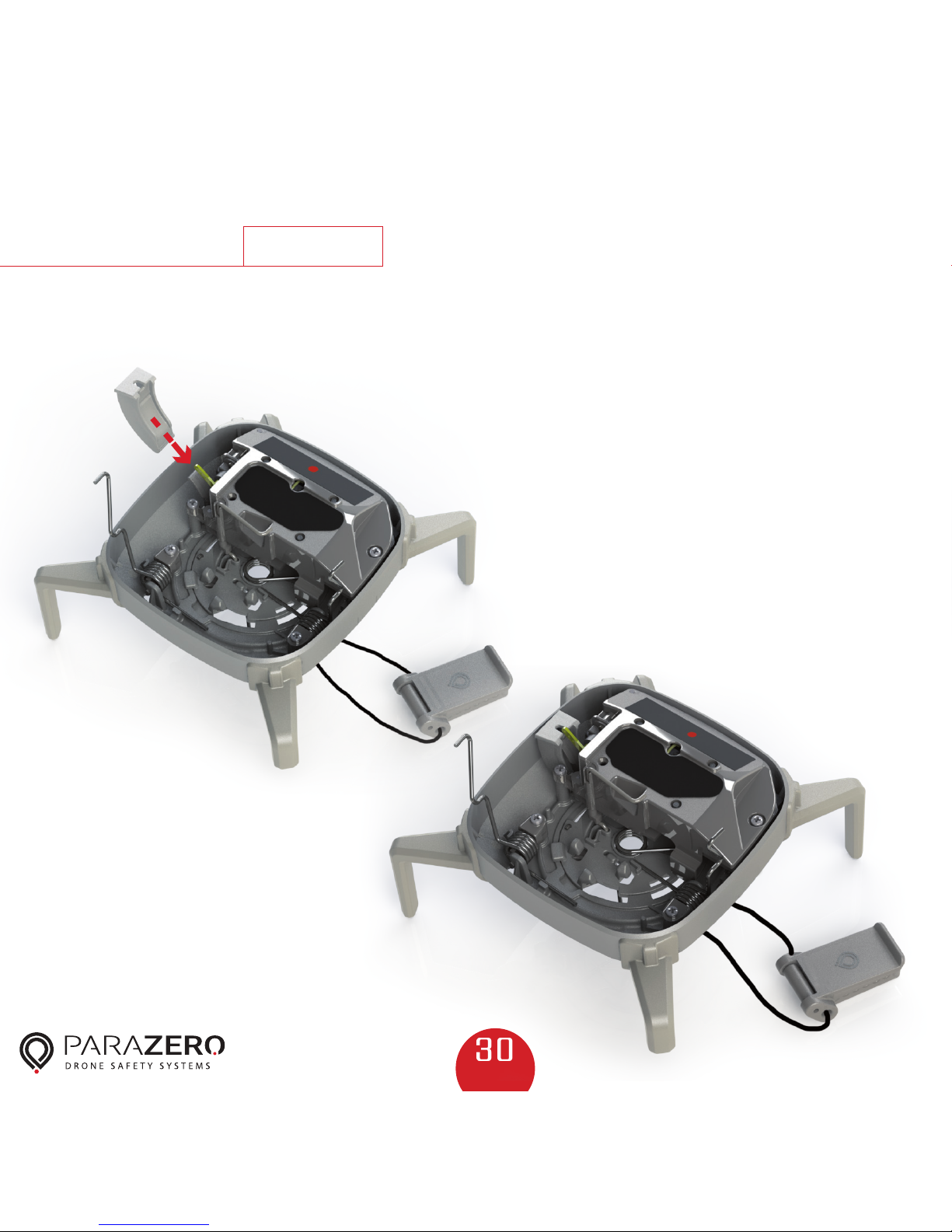
30
Step
Repacking
3
Place the Safety insert on the activation lever, in order to
avoid unintentional activation.

31
Step
Repacking
Push down the two main
springs and secure them in
place on the hooks in the
base of the system.
2
1
4

32
Step
Repacking
5
Place the Inner stage on top of the folded springs.
Ensure that the parachute strings are guided through the
indented gap between the platform and the system, as
shown below.

33
Step
Repacking
6
Verify that the parachute strings are not tangled, twisted,
knotted or damaged in any way.
With one hand, hold the parachute from the center of
the canopy, with the other hand in a ring shape, slide
downwards along the parachute until you reach the
parachute strings, so that the parachute is closed.
Check the strings
Fold parachute
1 2

34
Step
Repacking
7
Fold the parachute and strings back and forth until
they fit in your hand. The folded parachute should be
approximately the length of the parachute platform.
Zigzag fold
One loop Fold strings in an
eight shape
Combine the strings
with the parachute

35
Step
Repacking
8
Place the folded parachute inside the inner stage with the
strings facing downwards. Keep the parachute compressed
tightly in the platform. Take out the safety insert and
store it.

36
Step
Repacking
9
Verify the cover's orientation based on the label
underneath. Begin with inserting the two corners on the
parachute side. This will allow you to keep the parachute
compressed in place with the other hand.
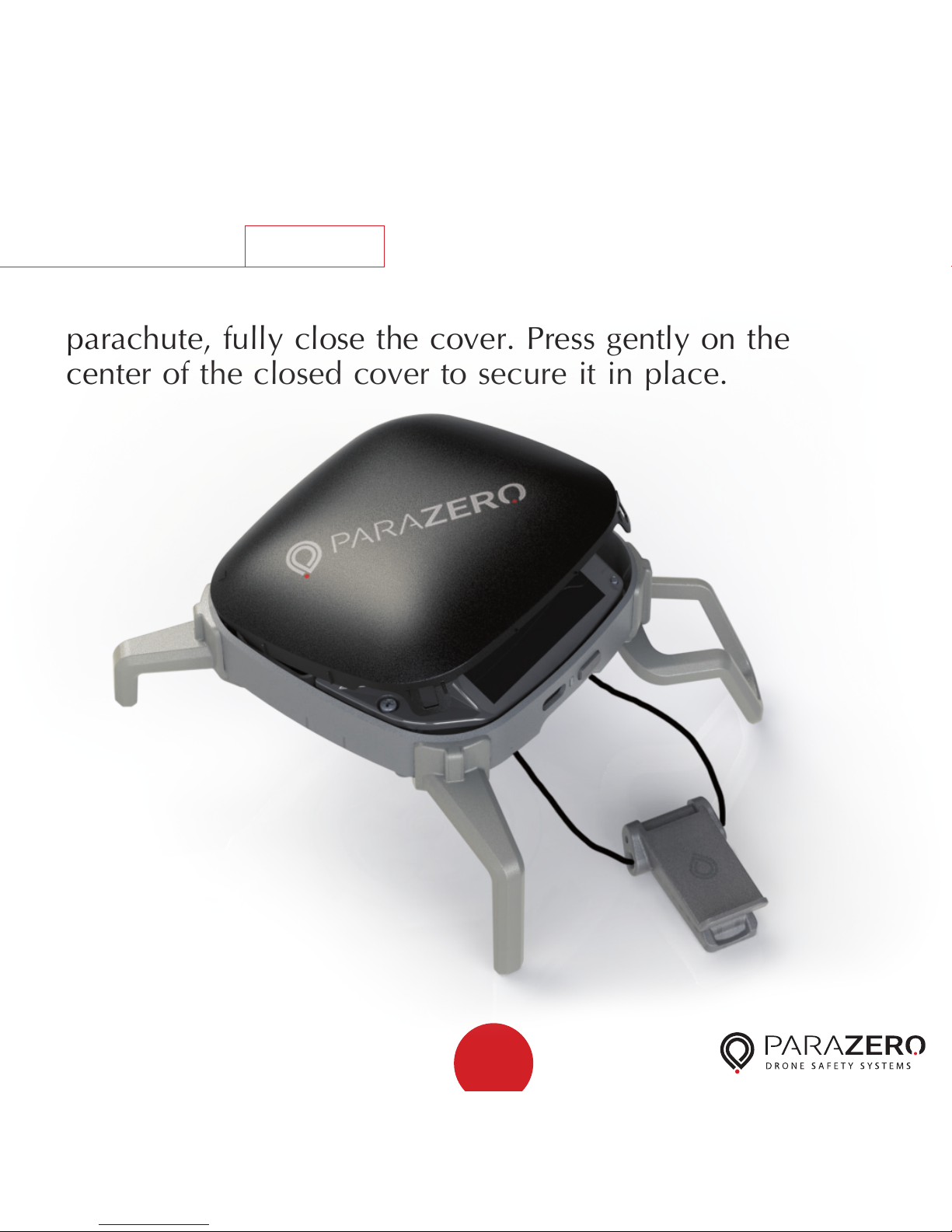
37
Step
Repacking
10
While removing the hand that was compressing the
parachute, fully close the cover. Press gently on the
center of the closed cover to secure it in place.

38
Step
Repacking
11
Ensure that parachute fabric is not sticking out of the gap
between the cover and the system
(up to 2mm is acceptable).

39
Step
Repacking
12
Insert the safety catch and store the system in a clean,
dry place for reuse.

40
LED System Status Corrective Action
1 Green Power up
2 Orange Power up Should charge battery
3 Red Power up Low battery, must charge battery
4 Steady Yellow System initiation
sequence
5 Blue Standby mode
6 Steady Green Armed mode
7 Steady Red System has
deployed
Turn the power switch to the OFF position and follow
the repacking instructions
8 Flashing Red Low battery Recharge the system for at least 20 minutes.
(The red flashing LED may be accompanied by other
colors)
9 Flashing Yellow
once
Remote Control
(RC) error
Make sure the RC cable is connected to the
predefined RC channel
10 Flashing Yellow
2 times
System not level
during initiation
sequence
Ensure that the system is level
System Status and Troubleshooting

41
Installing
Other Specifications
Warranty
One year or first deploymont
Maximum Altitude Above Sea Level
6000 meters (19,700 feet)
Maximum Speed
72 kilometers per hour (43.5 miles per
hour)
Maximum Wind Speed
10 meters per second (19.5 knots)
Temperature (°C)
0-40
Weight
160 grams (0.35 lbs.)
LED System Status Corrective Action
11 Flashing
Yellow 3 times
Onboard
storage erro
Erase onboard storage using the ParaZero
Desktop Application
System Status and Troubleshooting continued

42
Compliance Information
FCC Compliance Notice
This device complies with part 15 of the FCC Rules. Operation is subject to the following
two conditions: (1) This device may not cause harmful interference, and (2) this device
must accept any interference received, including interference that may cause
undesired operation.
Any changes or modifications not expressly approved by the party responsible for
compliance could void the user’s authority to operate the equipment.
This equipment has been tested and found to comply with the limits for a class B digital
device, pursuant to part 15 of the FCC Rules. These limits are designed to provide
reasonable protection against harmful interference in a residential installation. This
equipment generates, uses and can radiate radio frequency energy and if not installed
and used in accordance with the instructions, may cause harmful interference to radio
communications. However, there is no guarantee that interference will not occur in
a particular installation. If this equipment does cause harmful interference to radio or
television reception, which can be determined by turning the equipment off and on, the
user is encouraged to try to correct the interference by one or more of
the following measures:
- Reorient or relocate the receiving antenna.
- Increase the separation between the equipment and receiver.
- Connect the equipment into an outlet on a circuit different from that to which the
receiver is connected.
- Consult the dealer or an experienced radio/TV technician for help.
The FCC Compliance Statement is available online at parazero.com/FCC-compliance
EU Compliance Statement
The EU Declaration of Conformity is available online at parazero.com/EU-compliance
 Loading...