

ParaZero SafeAir M200 Installation Manual

SafeAir M200
INSTALLATION GUIDE

Table of Contents
CHAPTER 1 – SAFETY INSTRUCTIONS ................................................................................ 4
CHAPTER 2 – PACKAGE CONTENTS ................................................................................. 6
CHAPTER 3 – INSTALLATION.............................................................................................. 7
3.1 Connecting the Mounting Legs to the Drone ................................................................................. 7
3.2 Connecting the TerminateAir to the Drone..................................................................................... 8
3.3 Connecting the Electrical Wires....................................................................................................... 9
3.4 Connecting the Parachute System to the Legs ............................................................................ 10
3.5 Activating the System ..................................................................................................................... 10
3.6 Takeoff and Landing ....................................................................................................................... 13
CHAPTER 4 – OPERATING GUIDELINES ........................................................................... 14
4.1 Preflight ............................................................................................................................................. 14
4.2 Takeoff .............................................................................................................................................. 14
4.3 Before Landing ................................................................................................................................ 14
4.4 After Landing ................................................................................................................................... 14
4.5 Replacing the batteries .................................................................................................................. 14
4.6 Troubleshooting ............................................................................................................................... 15
List of Figures
Figure 1 – SafeAir M200 System ................................................................................................................. 4
Figure 2 – SafeAir M200 Safety Cover and Safety Pin ............................................................................ 5
Figure 3 – SafeAir M200 Package Contents ............................................................................................ 6
List of Tables
Table 1 – SafeAir M200 Package Contents ............................................................................................. 6
Important Notice
Copyright © 2018 ParaZero Drone Safety Systems. All rights reserved.
All intellectual property rights in this publication are owned by ParaZero Drone Safety Systems and protected by
applicable copyright laws and international treaty provisions. ParaZero Drone Safety Systems retains all rights not
expressly granted. No part of this publication may be reproduced in any form whatsoever or used to make any
derivative work without prior written approval by ParaZero Drone Safety Systems. All other trademarks are the property
of their respective owners. Other company and brand products and service names are trademarks or registered
trademarks of their respective holders
.
Document Information
SafeAir M200 Installation Guide
PZ-GE-098
Number of pages: 15
Last update: 8.10.2018
SafeAir™ M200 Installation Guide
2
www.parazero.com

Contact Information
Tel – +972-36885252
30 Dov Hoz
Kiryat Ono, Israel 5555626
www.parazero.com
About This Guide
This guide describes the installation of the ParaZero SafeAir M200 drone safety system that is compatible
for your DJI M200/210/210RTK drone.
SafeAir™ M200 Installation Guide
3
www.parazero.com
1
Caution Before you start the installation, read these safety instructions carefully!
Follow the instructions in this guide in the exact order in which they are presented, in order
to ensure your own safety as well as the safety of others.
Installation video: A step by step video can be found here: https://youtu.be/fA9Y4CcYFeA
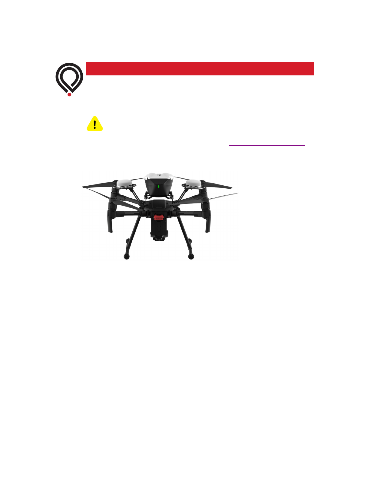
The ParaZero SafeAir M200 is a safety system designed to deploy almost instantaneously, by
using a special pyrotechnic mechanism, which must be handled with caution.
Figure 1 – SafeAir M200 System
The system incorporates two safety elements –
•
A Safety Pin (see Figure 2)
The safety pin electrically prevents the activation of the system. The system is packed
with the safety pin connected to the system. Do not remove the safety pin until
specifically instructed to do so in this guide.
The safety pin is removed just before flight, as described in Chapter 4, Operating
Guidelines on page 14.
SafeAir™ M200 Installation Guide
4
www.parazero.com
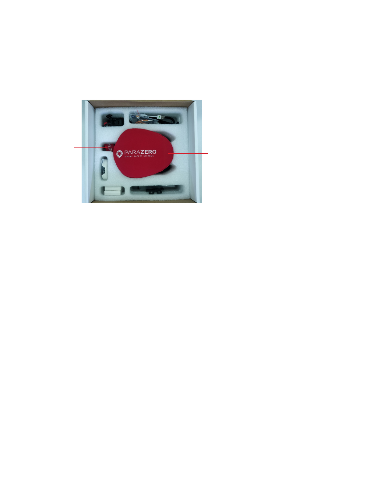
Safety Cover
Safety Pin
•
A Safety Cover (see Figure 2)
The safety cover physically prevents the deployment of the parachute, in case of an
unintended deployment. It is designed for safety during transportation, storage and for
applying at the end of each flight day. It is also highly recommended to put the cover
back on after each flight for added safety. The cover is also designed for protection
against external damage. The system is provided with the cover stretched over the
parachute canister.
Do not remove the safety cover until you complete the installation, and you are ready to
fly.
Figure 2 – SafeAir M200 Safety Cover and Safety Pin
SafeAir™ M200 Installation Guide
5
www.parazero.com
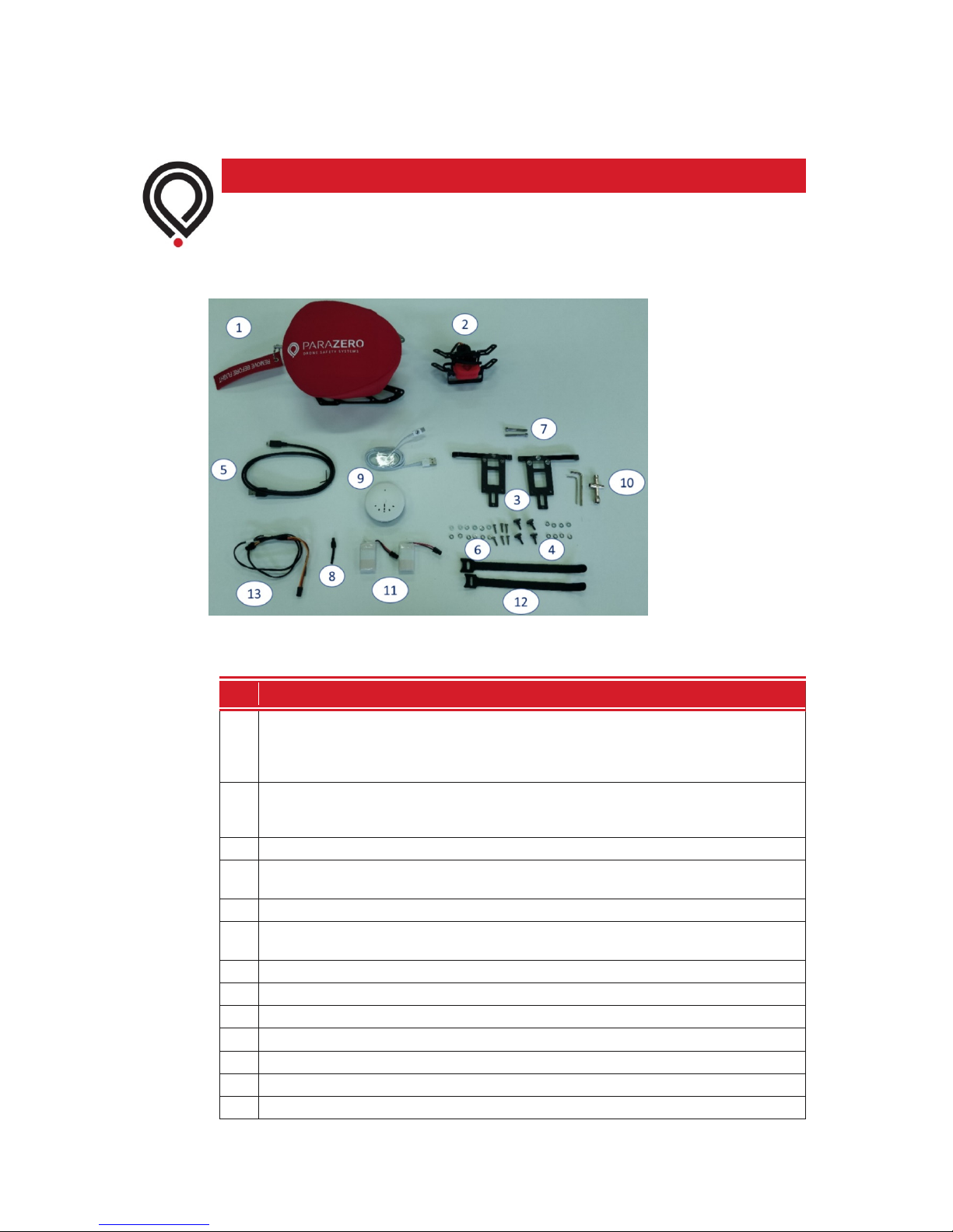
The SafeAir M200 package includes the parts shown in Figure 3.
2
Figure 3 – SafeAir M200 Package Contents
Table 1 – SafeAir M200 Package Contents
# Description
The main parachute system, which contains the SMARTAIR smart computer and its
electronics plus all other electronics, is preinstalled on the mounting plate and
1
ready for use. The system is covered with the safety cover and secured by the
safety pin.
The TerminateAir M200 with one cable connected to it. The TerminateAir flight
2
termination system stops the power to the rotors should a critical malfunction
occur.
3
Two mounting legs.
Four thumb screws for fast connection of the system plus four washers and four
4
spring washers.
5
One mini-USB cable for data management and firmware updates.
Six mounting leg connection screws to the air-vehicle plus six washers and six spring
6
washers.
7
Two long screws to connect the TerminateAir to the air-vehicle.
8
Pyro-dummy*
9
The M200 battery charger with USB cable for battery charging.
10 A set of tools for the connection.
11
Three batteries.
12
Cable mounting straps.
13
RC cable for optional manual activation. Can be enabled upon demand.
* For tests and troubleshooting only.
SafeAir™ M200 Installation Guide
6
www.parazero.com
 Loading...