

Page 1
Operating Instructions
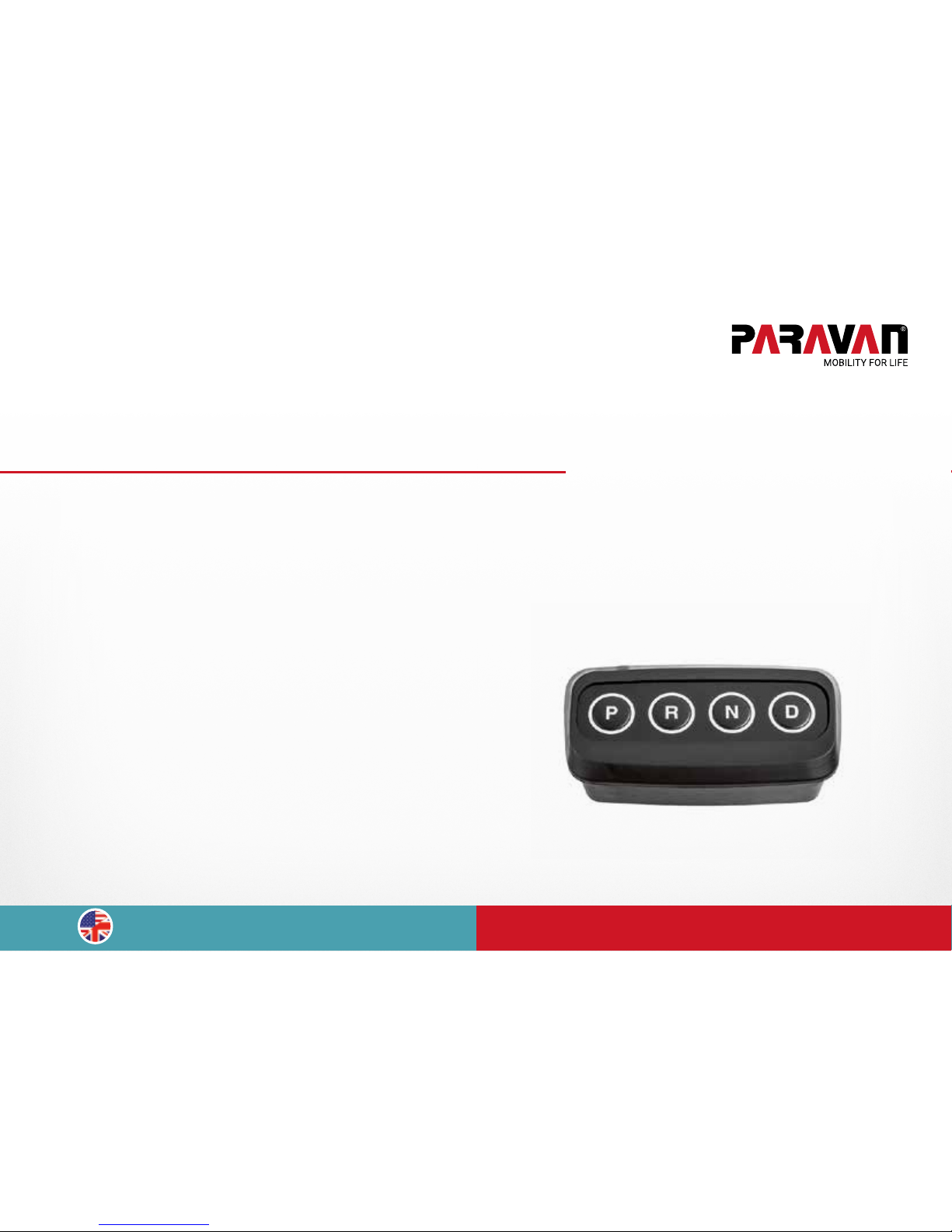
The Paravan Gear Control
www.paravan.com
EN/US V2.0
Translation of the original
operating instructions
Page 2

Publisher and copyright: PARAVAN GmbH, 72539 Pfronstetten-Aichelau, Germany
Issuing date: 1.1.2017
Document number: GC Benutzerhandbuch V2.0 EN-US
Page 3
3
Dear Customer
These operating instructions describe the functions of the PARAVAN
®
Gear Control. We ask that you ple-
ase read the following pages carefully so that you can make optimal use of the systems. Please keep this
maintenance manual accessible in your vehicle for later reference.
If you still have questions or suggestions regarding the secondary systems, please do not hesitate to
contact us.
Drive safely!
Your PARAVAN Team
Page 4

Table of contents
4
Table of contents
General facts
1. About these operating instructions ......................................................................6
1.1 General facts ............................................................................................................................ 6
1.1.1 Driving direction information .................................................................................................. 6
1.1.2 Technical documentation status ............................................................................................ 7
1.1.3 Copyright .................................................................................................................................. 8
2. Safety information ...............................................................................................9
2.1 Generally applicable safety information ................................................................................. 9
2.2 Preventing hazards, preventive measures ............................................................................. 10
2.3 Exclusion of liability ................................................................................................................. 11
Operate
2.4 Gear Control ............................................................................................................................ 12
2.4.1 Function .................................................................................................................................... 12
2.4.2 Operating elements ................................................................................................................. 14
2.4.3 Operation .................................................................................................................................. 16
2.4.4 Emergency operation, emergency switch .............................................................................. 19
Help
2.5 System diagnosis .................................................................................................................... 23
2.5.1 Indication of current errors ..................................................................................................... 23
3. Your link to the PARAVAN Customer Service .......................................................24
3.1 Hotline ...................................................................................................................................... 24
3.1.1 List of service partners ............................................................................................................ 25
Page 5
Index of gures
5
Index of gures
Fig. 1: Driving direction ....................................................................................................................... 8
Fig. 2: Gear Control ............................................................................................................................. 14
Fig. 3: Driving gear display ................................................................................................................. 15
Fig. 4: Sub-gear display ...................................................................................................................... 15
Fig. 5: Bedienfeld Gear Control .......................................................................................................... 16
Fig. 6: Integriertes Bedienfeld ............................................................................................................ 16
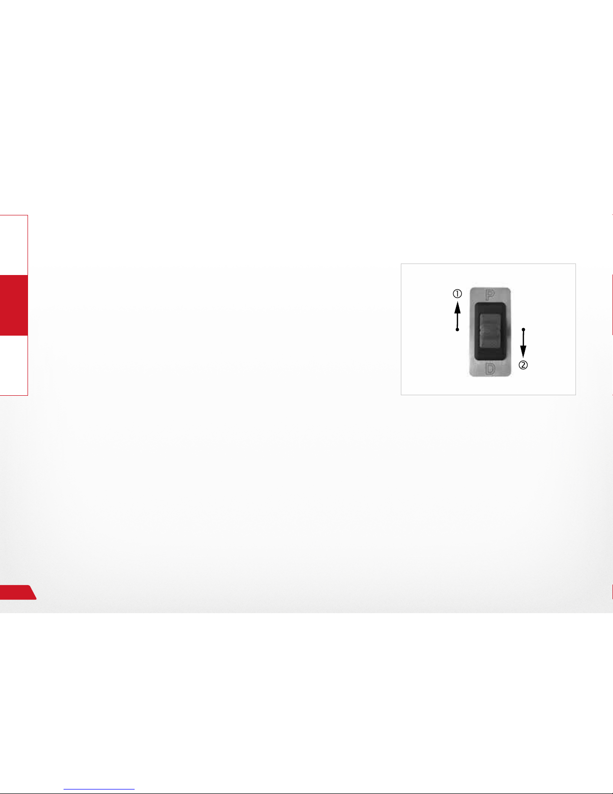
Fig. 7: Emergency switch .................................................................................................................... 17
Fig. 8: Fahrstufe R, N und D ................................................................................................................ 18
Fig. 9: Driving gear D ........................................................................................................................... 19
Fig. 10: Park position P ......................................................................................................................... 20
Fig. 11: Emergency switch .................................................................................................................... 22
Fig. 12: Selecting driving gear .............................................................................................................. 23
Fig. 13: Shift diagram ............................................................................................................................ 24
Page 6
General
Operate Help
About these operating instructions
6
1. About these operating instructions
1.1 General facts
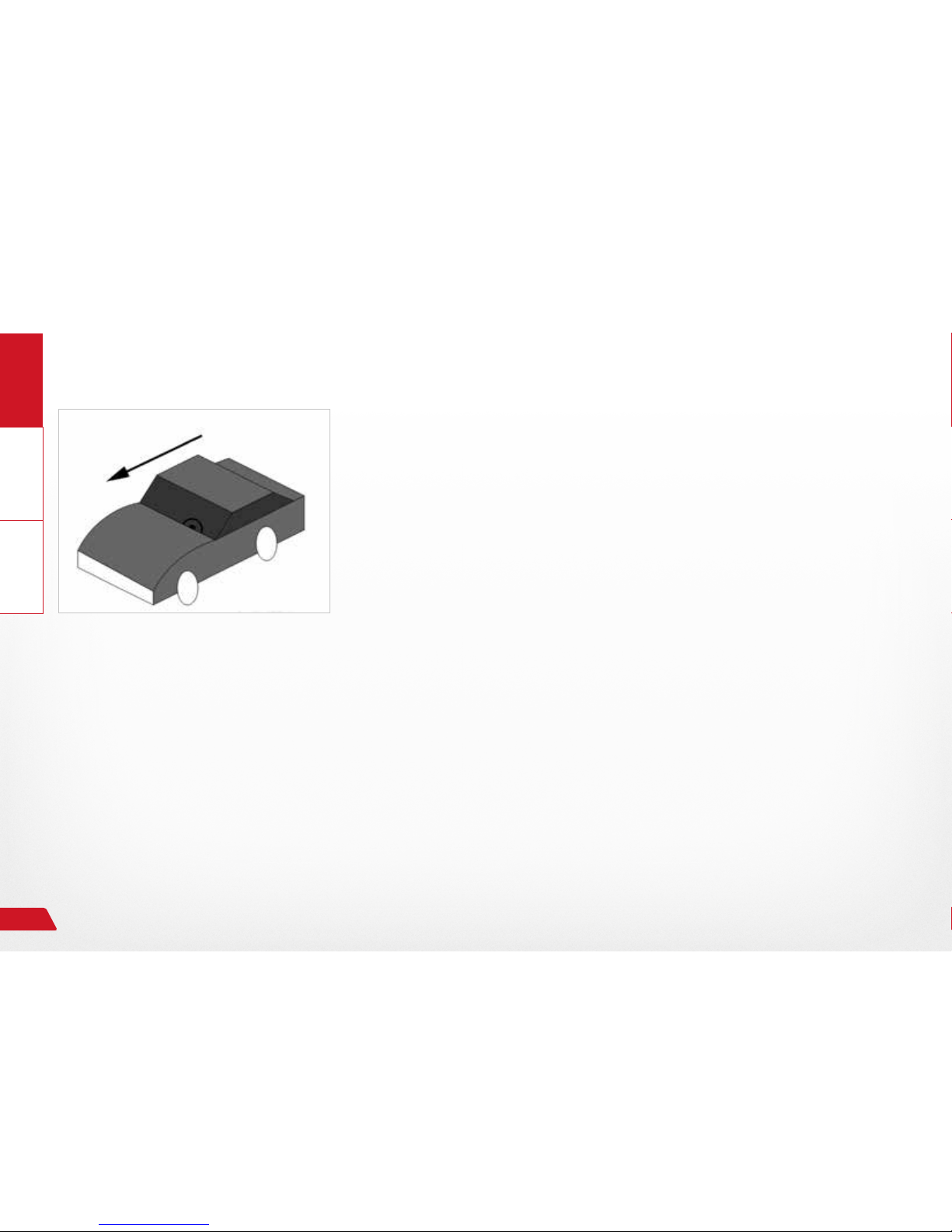
Fig. 1: Driving direction
These operating instructions contain information regarding the operation of the secondary systems. The most important product features are
listed and described in the following. All listed product features may be
combined with one another in various versions and functions.
These operating instructions are a product component of the
PARAVAN® Gateway System and must always be kept in the
vehicle to ensure that you have quick access to important information. All instructions concerning sides and directions are
always described from the perspective of the operator looking
in the driving direction!
1.1.1 Driving direction information
Page 7
General
OperateHelp
About these operating instructions
7
1.1.2 Technical documentation status
All information regarding technical data/specications, illustrations, and information in these operating instructions corresponds to the version produced following revision in November 2015.
The operating instructions for the PARAVAN® Gateway System were compiled in German and may
be translated into other languages. The German version is legally binding in the event of any discrepancies.
Page 8

General
Operate Help
Safety information
8
1.1.3 Copyright
This documentation, including all of its parts, is copyright-protected. Any rights derived from the copyright, in
particular those of translation, reproduction, presentation, extraction of illustrations and tables, radio broad-
cast, micro-lm or reproduction in any other form and storage on data processing equipment are reserved,
even for partial use thereof.
Duplication of this publication or parts thereof is permitted only within the limits of the legal provisions of
the German Copyright Law of September 9, 1965, in its current version. It is essentially subject to payment.
Infringements are subject to the legal penalties contained in the copyright law
› Copyright © PARAVAN GmbH 2017. All rights reserved!
Page 9
General
OperateHelp
Safety information
9
2. Safety information
2.1 Generally applicable safety information
For your protection and the protection of people in your surroundings and the environment, the following
safety information must be noted and followed without fail.
HAZARD!
Risk of death to anyone operating a vehicle with a Gear Con-
trol that is not in the original or as-delivered condition.
Risk of death due to loss of control of the vehicle due to impermissible conversions.
Material damage to control elements on the Gear Control
caused by unapproved or incorrectly installed orthopedic attachments.
› Do not implement any technical changes to the control ele-
ments of the system.
› Only use the Gear Control in its original or delivery state.
› Only use original or approved orthopedic attachments.
Page 10

General
Operate Help
Safety information
10
2.2 Preventing hazards, preventive measures
The vehicle and system can only be safely operated by adhering to and applying the safety information and
measures for preventing undesirable events (personal injury) or conditions (property damage).
It is essential that you familiarize yourself with the contents of this safety information before using
or operating the vehicle with the Gear Control.
This prevention requires the measures specied for the operator in the
› PARAVAN® Gear Control operating instructions
to be diligently and carefully implemented.
Page 11
General
OperateHelp
Safety information
11
2.3 Exclusion of liability
Only by heeding and applying the knowledge obtained through the
› PARAVAN® Gear Control operating instructions
can correct and malfunction-free operation of the PARAVAN
®
Gear Control be ensured.
PARAVAN GmbH accepts no liability or warranty for damage or operational malfunctions due to
failure to adhere to these operating instructions or due to changes made to the PARAVAN® Gear
Control.
Page 12
Operate Help
General
12
2.4 Gear Control
Electronic selector mechanism of the driving gears, gear
control, has the same function as the original selector lever of
the driving gears of an automatic transmission.
This is only possible for vehicles with the originally installed automatic
transmission.
› The system controls an electric drive with a positioning sensor for
shifting the driving gears on the automatic transmission.
Function of the system:
› Selection and shifting of the desired gear P, R, N, D (and subgears 1,
2, and 3).
› Activation of the indicator light (symbol) in the vehicle and on the
control element.
Function of the emergency switch (emergency operation):
› Bypasses the gear control system in an emergency or if there is a
malfunction in the system. Directly controls the servo motor of the
automatic transmission.
› Activation of the indicator light (symbol) in the vehicle.
Fig. 2: Gear Control
2.4.1 Function
Page 13

GeneralOperateHelp
13
Display of the driving gear in the control element
The selected or shifted driving gear is displayed on the instrument cluster of the vehicle and in the control element.
The manner of display for the instrument cluster in the vehicle is
described in the respective vehicle documents of the manufacturer.
The signaling and display of the driving gear/sub-gear in the control
element (pure control) is indicated by a
› colored lit ring around the respective driving gear
→ Continuously lit for driving gears P, R, N, and D.
→ Flashing light for sub-gears 1, 2, and 3 of driving gear D.
The ashing frequency changes as a function of the selected
sub-gear 1, 2, or 3.
Your service technician can adapt the color of the display and
of the ring to the color of the displays in the vehicle.
Fig. 3: Driving gear display
Fig. 4: Sub-gear display
Page 14
Operate Help
General
14
The primarily used control elements are described. Other
control elements are possible. Your service technician can
address any additional instructions that may be necessary.
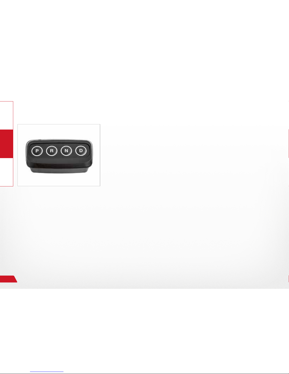
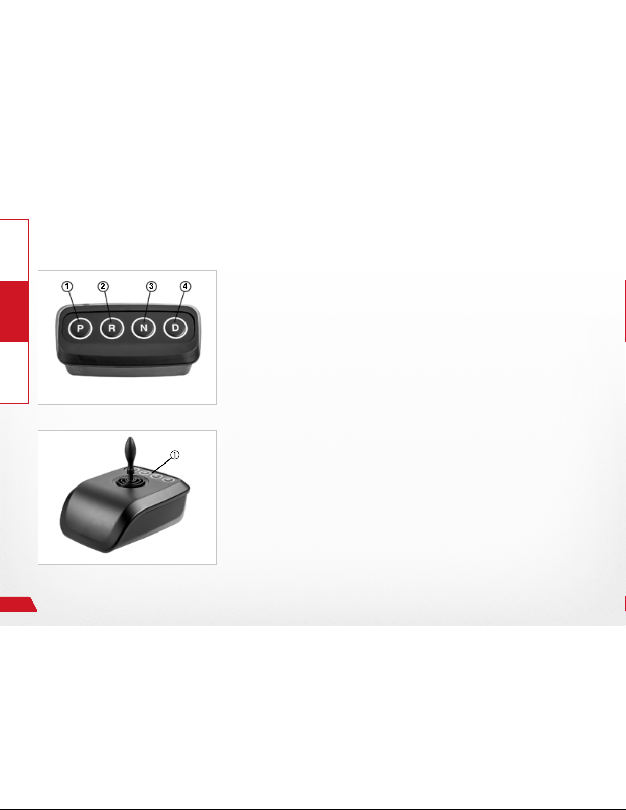
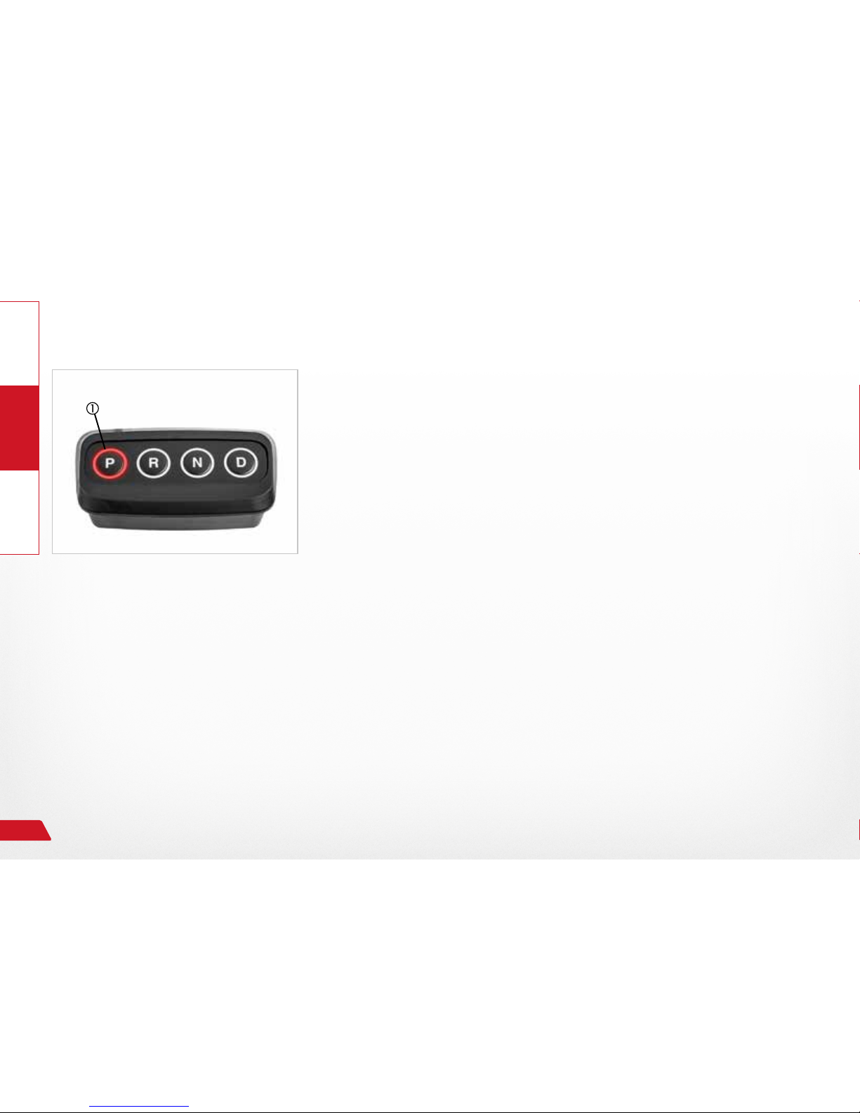
Autonomous control panel
4 pushbuttons, lit for feedback of the action.
› Park position „P“
→ Parking, engaging the parking block in automatic transmissions.
› Driving gear „R“
→ Reverse, shifting into reverse gear.
› Driving gear „N“
→ Neutral (idle), engine and transmission are decoupled.
› Driving gear „D“
→ Drive, forward driving with automatic gear selection.
→ Selection of the sub-gears 1, 2, or 3.
Integrated control panel e.g. in the joystick
The same function or operation as with an autonomous
control panel.
Fig. 5: Bedienfeld Gear Control
2.4.2 Operating elements
Fig. 6: Integriertes Bedienfeld
Page 15
GeneralOperateHelp
15
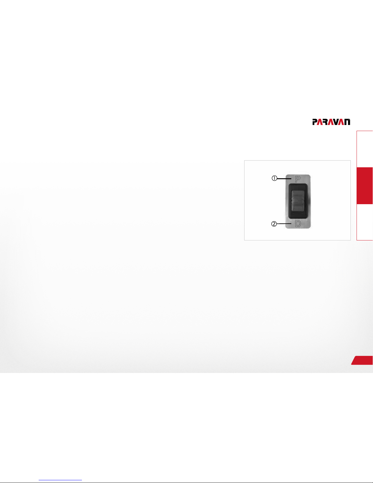
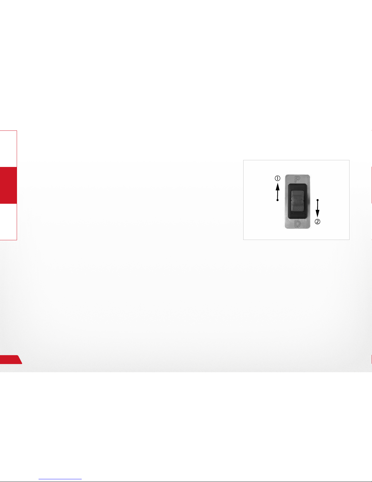
Emergency switch
The emergency switch of the gear control is part of the safety
mechanisms in the PARAVAN SPACE DRIVE® II driving system.
This is an autonomous toggle switch with a rocker switch for signaling.
› Park position „P“
→ Parking, engaging the parking lock in automatic transmissions.
Driving gears „R“ and „N“ are selected by renewed activation or
by pressing or of the rocker switch.
› Driving gear „D“
→ Drive, shifting into forward gear.
→ Selection of the sub-gears by pressing again.
The installation position of the emergency switch may deviate
depending on the vehicle. Get to know the installation position
of the emergency switch so that you can locate it immediately
in an emergency!
Fig. 7: Emergency switch
Page 16
Operate Help
General
16
2.4.3 Operation
Selecting driving gears „R“, „N“, and „D“
The vehicle is in park position „P“ .
› Press and hold brakes
› Press the pushbutton for the desired driving gear (R , N , or D )
.
→ The selected driving gear will be engaged.
→ The engaged driving gear will be displayed on the instrument clus-
ter of the vehicle and on the control element .
› Release brake.
→ Vehicle will execute the selected action.
The switch between the driving gears (P, R, N, and D) can only
occur with the vehicle‘s driving brake engaged.
Fig. 8: Fahrstufe R, N und D
Page 17
GeneralOperateHelp
17
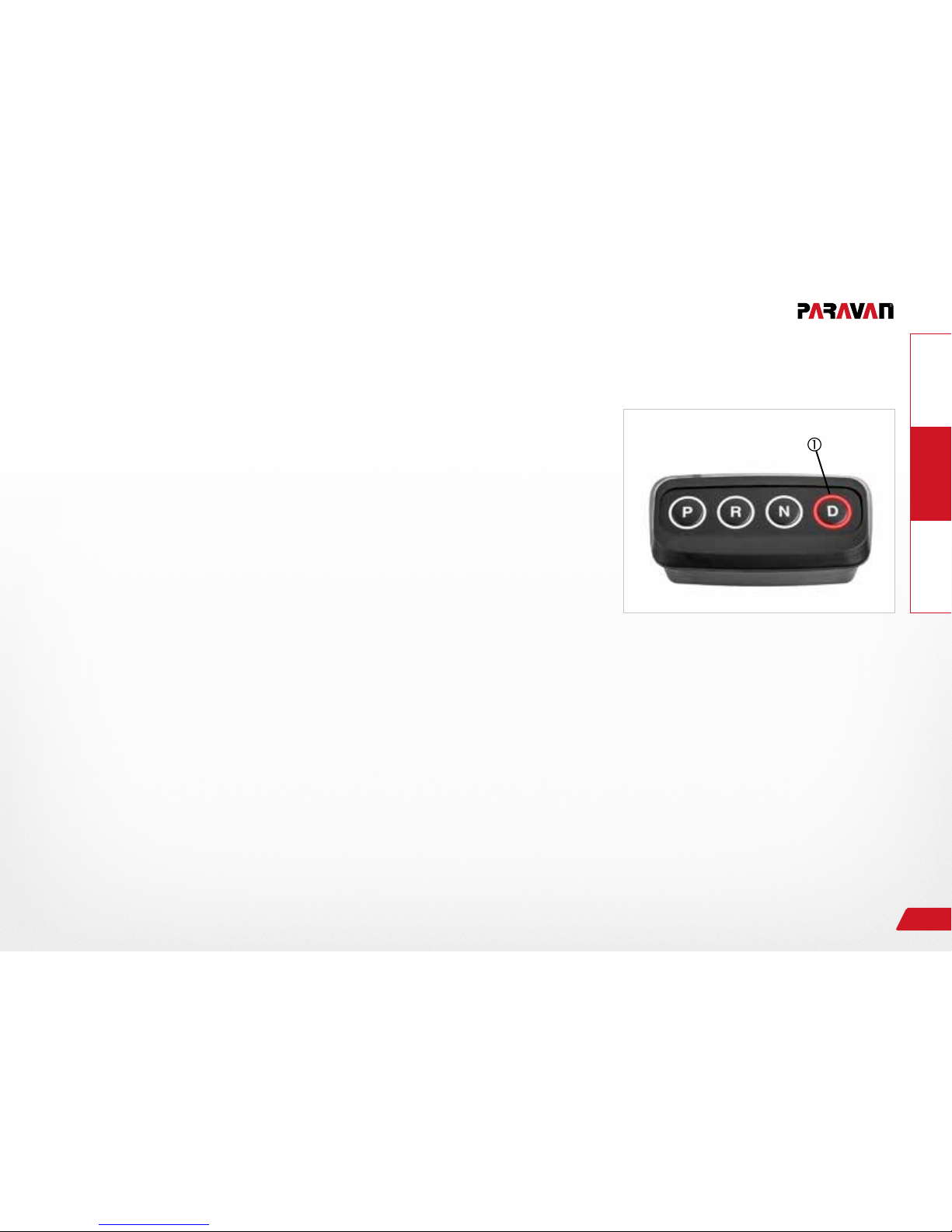
Selecting the „D“ sub-gears (manual mode)
In a normal drive in driving gear „D“, it is sometimes necessary based on the driving situation, e.g. overtaking maneuver,
driving up and down mountains, to select a different driving
gear or sub-gear of „D“.
› Press the „D“ pushbutton.
→ Sub-gear „1“ will be engaged.
› Press „D“ pushbutton again.
→ Sub-gear „2“ will be engaged.
› Press „D“ pushbutton again.
→ Sub-gear „3“ will be engaged.
› Press „D“ pushbutton again.
→ Driving gear „D“ will be engaged.
The driver can shift directly into driving gear „D“ from any sub-gear
through a longer pressing of the „D“ pushbutton.
The engaged driving gear will be displayed on the instrument
cluster of the vehicle and on the control element .
Fig. 9: Driving gear D
Page 18
Operate Help
General
18
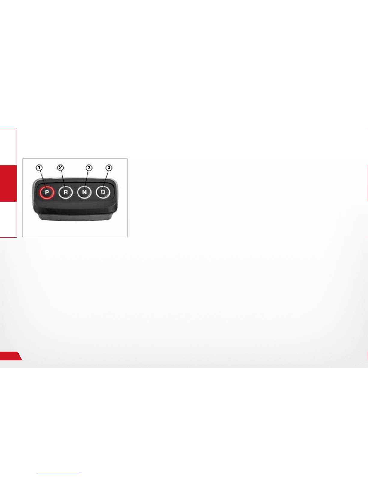
Selecting driving gear „P“, parking
› Bring the vehicle to a stop.
› Press and hold brakes
› Press the park position „P“ pushbutton.
→ The parking lock will be engaged on the automatic transmission.
→ The engaged driving gear will be displayed on the instrument clus-
ter of the vehicle and on the control element .
› Set parking brake.
Always support the automatic transmission in the park
position with the parking brake!
› Release brake.
→ Park position is then complete.
Fig. 10: Park position P
Page 19
GeneralOperateHelp
19
2.4.4 Emergency operation, emergency switch
Only use emergency switch during system failures or emergency situations!
WARNING
Risk of destroying vehicle and system components when ope-
rating a driving system in emergency mode caused by overloading the mechanical system.
Risk of material damage to the vehicle or the vehicle units in
emergency mode due to failure of the driving system, e.g. nal
switch-off of the automatic transmission.
› Shift into driving gears slowly one after another using the
emergency switch.
› Follow the driving gear display on the instrument cluster.
› Do not shift beyond driving gear "D" or select one of sub-
gears 1, 2, or 3 of "D"!
› Avoid frequent changes in gears.
› Establish proper operating condition of the vehicle and dri-
ving system.
› Find a service station and eliminate the malfunction.
Page 20
Operate Help
General
20
Selecting driving gears "D" and "P" via the emergency switch
Selecting driving gear "D":
› Bring the vehicle to a stop.
› Press and hold brakes
› Activate rocker switch (toggle switch) in the "D" direction.
→ Driving gear "D" will be engaged.
→ The engaged driving gear will be displayed on the instrument clus-
ter of the vehicle.
Selecting driving gear "P", parking:
› Bring the vehicle to a stop.
› Press and hold brakes
› Activate rocker switch (toggle switch) in the "P" direction.
The parking lock will be engaged on the automatic transmission.
→ The engaged driving gear will be displayed on the instrument cluster of the vehicle.
› Set parking brake.
Fig. 11: Emergency switch
Page 21
GeneralOperateHelp
21
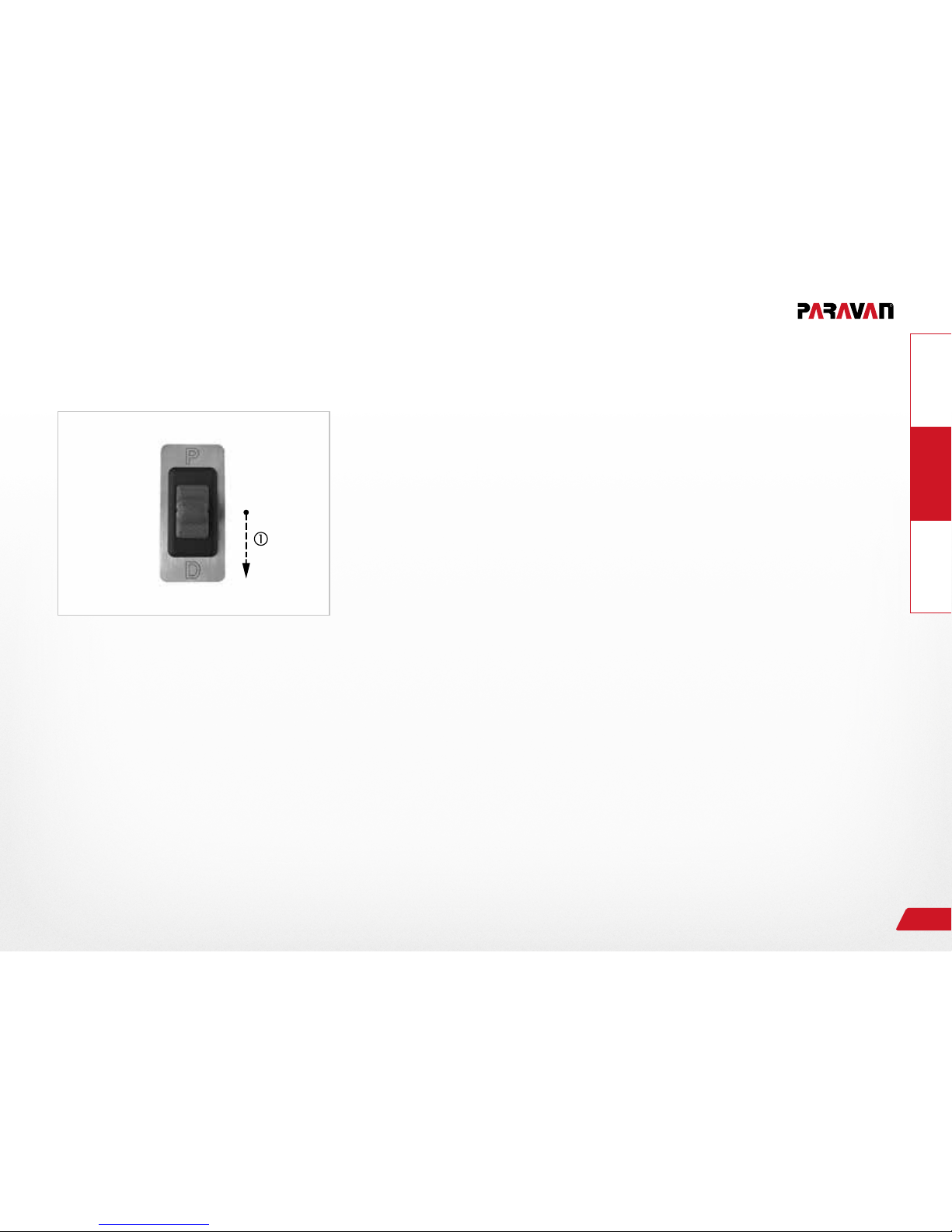
Fig. 12: Selecting driving gear
Selecting driving gears "R" and "N" via the emergency switch
The switch between the driving gears (P, R, N, and D) can only
occur with the vehicle's driving brake engaged.
› Bring the vehicle to a stop.
› Press and hold brakes
› Press and hold rocker switch (toggle switch) in the "D" direction in
till the desired driving gear is displayed on the vehicle's instrument
cluster.
→ The selected driving gear will be engaged.
→ The engaged driving gear will be displayed on the instrument clus-
ter of the vehicle.
› Release brake.
→ Vehicle will execute the selected action.
Page 22
Operate Help
General
22
Fig. 13: Shift diagram
Shifting diagram of gear control with emergency switch
The servo motor for the automatic transmission shifts through
the driving gears from the "P" position in the direction of "D"
due to activation of the toggle switch.
This means the driving gears are selected and shifted in sequence
through the
› pressing and holding of the rocker switch in the "D" direction
→ R, N, D (manual STOP! back with )
Selecting again causes a further shift into sub-gears 1, 2, and
3 of driving gear "D". The sub-gears cannot be selected during
emergency operation.
› pressing and holding of the rocker switch in the "P" direction
→ D, N, R, and P (manual STOP! forward with )
Page 23

General
OperateHelp
23
2.5 System diagnosis
2.5.1 Indication of current errors
All fault messages can be read with the Diagnostic Tester. Each PARAVAN service partner is
capable of performing a vehicle and systems diagnosis.
The fault log provided includes the following information for the service technician:
› Error code
→ Error code of the error that occurred.
Page 24
General
Operate Help
Your link to the PARAVAN Customer Service
24
3. Your link to the PARAVAN Customer Service
3.1 Hotline
PARAVAN Customer Service will gladly answer any questions related to secondary systems or
obtain spare parts for your PARAVAN system.
If you have a problem with your PARAVAN system or if you need help or further information, you can reach
our PARAVAN Customer Service Division during our business hours
› Monday to Friday from 8:00 AM to 12:00 PM and 1:00 AM to 5:00 PM
directly at the following phone numbers:
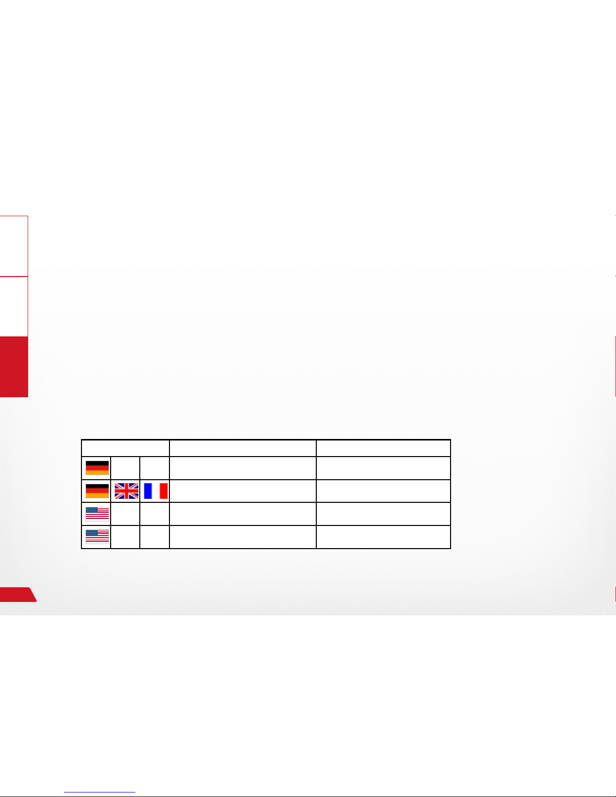
Language Contact Phone number
Customer Service +49 (0) 7388-9995 77
Mr. Alexander Freiss +49 (0) 7388-9995 945
Customer Service (USA) 011-49-160 431 62 48
Freecall (USA) +1 844 887 0723
Page 25

General
OperateHelp
Your link to the PARAVAN Customer Service
25
3.1.1 List of service partners
Maintenance work may only be carried out by certied dealers or certied PARAVAN® Gateway
technicians. Maintenance work may only be performed by trained technicians; never carry out
maintenance work yourself!
For additional quick help in your vicinity:
› Europe
› USA
Page 26

Notes
- - - - - - - - - - - - - - - - - - - - - - - - - - - - - - - - - - - - - - - - - - - - - - - - - - - - - - - - - - - - - - - -
- - - - - - - - - - - - - - - - - - - - - - - - - - - - - - - - - - - - - - - - - - - - - - - - - - - - - - - - - - - - - - - -
- - - - - - - - - - - - - - - - - - - - - - - - - - - - - - - - - - - - - - - - - - - - - - - - - - - - - - - - - - - - - - - -
- - - - - - - - - - - - - - - - - - - - - - - - - - - - - - - - - - - - - - - - - - - - - - - - - - - - - - - - - - - - - - - -
- - - - - - - - - - - - - - - - - - - - - - - - - - - - - - - - - - - - - - - - - - - - - - - - - - - - - - - - - - - - - - - -
- - - - - - - - - - - - - - - - - - - - - - - - - - - - - - - - - - - - - - - - - - - - - - - - - - - - - - - - - - - - - - - -
- - - - - - - - - - - - - - - - - - - - - - - - - - - - - - - - - - - - - - - - - - - - - - - - - - - - - - - - - - - - - - - -
- - - - - - - - - - - - - - - - - - - - - - - - - - - - - - - - - - - - - - - - - - - - - - - - - - - - - - - - - - - - - - - -
- - - - - - - - - - - - - - - - - - - - - - - - - - - - - - - - - - - - - - - - - - - - - - - - - - - - - - - - - - - - - - - -
- - - - - - - - - - - - - - - - - - - - - - - - - - - - - - - - - - - - - - - - - - - - - - - - - - - - - - - - - - - - - - - -
Page 27
- - - - - - - - - - - - - - - - - - - - - - - - - - - - - - - - - - - - - - - - - - - - - - - - - - - - - - - - - - - - - - - -
- - - - - - - - - - - - - - - - - - - - - - - - - - - - - - - - - - - - - - - - - - - - - - - - - - - - - - - - - - - - - - - -
- - - - - - - - - - - - - - - - - - - - - - - - - - - - - - - - - - - - - - - - - - - - - - - - - - - - - - - - - - - - - - - -
- - - - - - - - - - - - - - - - - - - - - - - - - - - - - - - - - - - - - - - - - - - - - - - - - - - - - - - - - - - - - - - -
- - - - - - - - - - - - - - - - - - - - - - - - - - - - - - - - - - - - - - - - - - - - - - - - - - - - - - - - - - - - - - - -
- - - - - - - - - - - - - - - - - - - - - - - - - - - - - - - - - - - - - - - - - - - - - - - - - - - - - - - - - - - - - - - -
- - - - - - - - - - - - - - - - - - - - - - - - - - - - - - - - - - - - - - - - - - - - - - - - - - - - - - - - - - - - - - - -
- - - - - - - - - - - - - - - - - - - - - - - - - - - - - - - - - - - - - - - - - - - - - - - - - - - - - - - - - - - - - - - -
- - - - - - - - - - - - - - - - - - - - - - - - - - - - - - - - - - - - - - - - - - - - - - - - - - - - - - - - - - - - - - - -
- - - - - - - - - - - - - - - - - - - - - - - - - - - - - - - - - - - - - - - - - - - - - - - - - - - - - - - - - - - - - - - -
Page 28

Notes
- - - - - - - - - - - - - - - - - - - - - - - - - - - - - - - - - - - - - - - - - - - - - - - - - - - - - - - - - - - - - - - -
- - - - - - - - - - - - - - - - - - - - - - - - - - - - - - - - - - - - - - - - - - - - - - - - - - - - - - - - - - - - - - - -
- - - - - - - - - - - - - - - - - - - - - - - - - - - - - - - - - - - - - - - - - - - - - - - - - - - - - - - - - - - - - - - -
- - - - - - - - - - - - - - - - - - - - - - - - - - - - - - - - - - - - - - - - - - - - - - - - - - - - - - - - - - - - - - - -
- - - - - - - - - - - - - - - - - - - - - - - - - - - - - - - - - - - - - - - - - - - - - - - - - - - - - - - - - - - - - - - -
- - - - - - - - - - - - - - - - - - - - - - - - - - - - - - - - - - - - - - - - - - - - - - - - - - - - - - - - - - - - - - - -
- - - - - - - - - - - - - - - - - - - - - - - - - - - - - - - - - - - - - - - - - - - - - - - - - - - - - - - - - - - - - - - -
- - - - - - - - - - - - - - - - - - - - - - - - - - - - - - - - - - - - - - - - - - - - - - - - - - - - - - - - - - - - - - - -
- - - - - - - - - - - - - - - - - - - - - - - - - - - - - - - - - - - - - - - - - - - - - - - - - - - - - - - - - - - - - - - -
- - - - - - - - - - - - - - - - - - - - - - - - - - - - - - - - - - - - - - - - - - - - - - - - - - - - - - - - - - - - - - - -
Page 29

- - - - - - - - - - - - - - - - - - - - - - - - - - - - - - - - - - - - - - - - - - - - - - - - - - - - - - - - - - - - - - - -
- - - - - - - - - - - - - - - - - - - - - - - - - - - - - - - - - - - - - - - - - - - - - - - - - - - - - - - - - - - - - - - -
- - - - - - - - - - - - - - - - - - - - - - - - - - - - - - - - - - - - - - - - - - - - - - - - - - - - - - - - - - - - - - - -
- - - - - - - - - - - - - - - - - - - - - - - - - - - - - - - - - - - - - - - - - - - - - - - - - - - - - - - - - - - - - - - -
- - - - - - - - - - - - - - - - - - - - - - - - - - - - - - - - - - - - - - - - - - - - - - - - - - - - - - - - - - - - - - - -
- - - - - - - - - - - - - - - - - - - - - - - - - - - - - - - - - - - - - - - - - - - - - - - - - - - - - - - - - - - - - - - -
- - - - - - - - - - - - - - - - - - - - - - - - - - - - - - - - - - - - - - - - - - - - - - - - - - - - - - - - - - - - - - - -
- - - - - - - - - - - - - - - - - - - - - - - - - - - - - - - - - - - - - - - - - - - - - - - - - - - - - - - - - - - - - - - -
- - - - - - - - - - - - - - - - - - - - - - - - - - - - - - - - - - - - - - - - - - - - - - - - - - - - - - - - - - - - - - - -
- - - - - - - - - - - - - - - - - - - - - - - - - - - - - - - - - - - - - - - - - - - - - - - - - - - - - - - - - - - - - - - -
Page 30
www.paravan.com
EN/US V2.0
Translation of the original
operating instructions
PARAVAN GmbH
Paravanstraße 5-10
72539 Pfronstetten-Aichelau
Germany
Phone: +49 (0) 73 88 / 99 95-60
Freecall: +1 844 887 0723
(US only)
Email: [email protected]
Operating instructions
The Paravan Gear Control
 Loading...