

Page 1
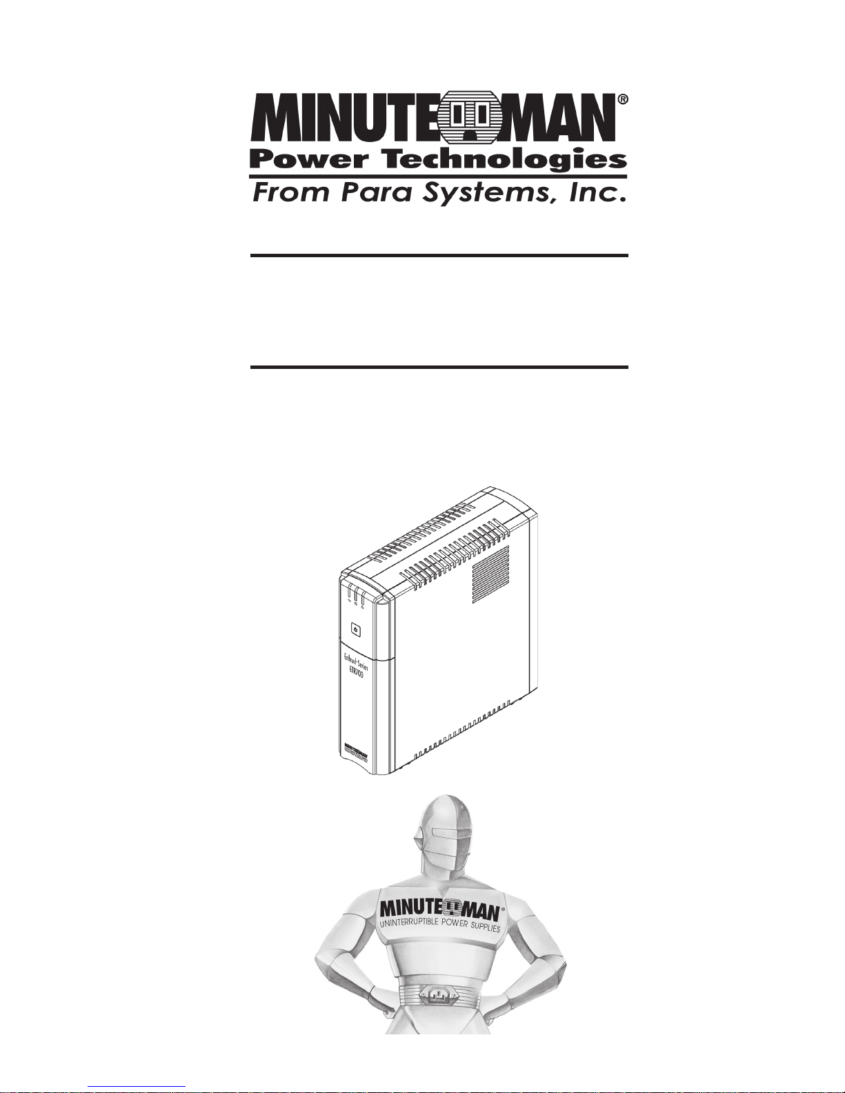
User's Manual
Entrust
Series UPS
Page 2

1
© Copyright 2007
1. Introduction 2
2. Controls and Indicators 6
3. Installation 7
4. Operation 10
5. Troubleshooting 12
6. Replacing the Battery 13
7. Obtaining Service 16
8. Specifications 17
9. Limited Product Warranty 19
A1 . Declaration of Conformity 20
English
Page 3
2
IMPORTANT SAFETY INSTRUCTIONS
SAVE THESE INSTRUCTIONS !
English
Thank you for purchasing this power protection product. It has been designed
and manufactured to provide many years of trouble free service.
Please read this manual before installing your Entrust Series UPS, models
ETR500, ETR700, ETR1000, ETR1500, ETR700p15, ETR1500p15 as it provides important information that should be followed during installation and maintenance of the UPS and batteries allowing you to correctly set up your system
for the maximum safety and performance. Included is information on customer
support and factory service if it is required. If you experience a problem with the
UPS please refer to the Troubleshooting guide in this manual to correct the
problem or collect enough information so that the Technical Support Department can rapidly assist you.
This symbol indicates "A TTENTION"
This symbol indicates "Risk of Electrical Shock"
This symbol indicates "Alternating Current Supply"
This symbol indicates "Alternating Current Supply Phase"
Page 4
3
WARNING: Risk of Electrical Shock. Hazardous live parts inside
these power supplies are energized from the battery even when the
AC input is disconnected.
CAUTION! T o de-energize the output s of the UPS:
1. If the UPS is on press and release the On/Off Button.
2. Disconnect the UPS from the AC wall outlet.
3. T o de-energize the UPS completely, disconnect the battery.
CAUTION! To reduce the risk of electrical shock in conditions
where the load equipment grounding cannot be verified, disconnect
the UPS from the AC wall outlet before inst alling a computer interface
cable. Reconnect the power cord only after all signaling connections
are made.
CAUTION! Connect the UPS to a two pole, three wire grounding
AC wall outlet. The receptacle must be connected to the appropriate
branch protection (circuit breaker or fuse). Connection to any other
type of receptacle may result in a shock hazard and violate local
electrical codes. Do not use extension cords, adapter plugs, or surge
strips.
English
CAUTION! T o reduce the risk of electrical shock with the installa-
tion of this UPS equipment and the connected equipment, the user
must ensure that the combined sum of the AC leakage current does
not exceed 3.5mA.
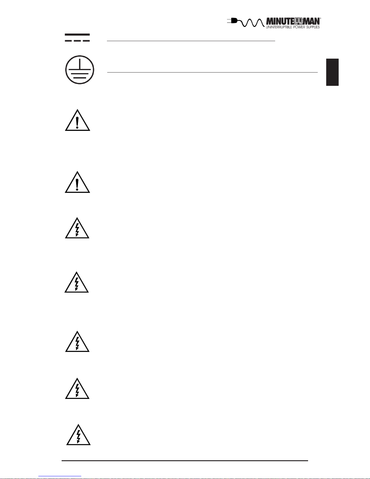
This symbol indicates "Direct Current Supply"
This symbol indicates "Equipment Grounding Conductor"
W ARNING: This Uninterruptible Power Supply contains potentially
hazardous voltages. Do not attempt to disassemble the UPS beyond
the battery replacement procedure. This UPS contains no user serviceable parts. Repairs and Battery replacement must be performed
by QUALIFIED SERVICE PERSONNEL ONL Y.
CAUTION! To reduce the risk of fire, connect only to a circuit
provided with 20 amperes maximum branch circuit over-current protection in accordance with the National Electric Code, ANSI/NFPA
70.
Page 5

4
English
After removing your UPS from its carton, it should be inspected for damage that
may have occurred in shipping. Immediately notify the carrier and place of
purchase if any damage is found. Warranty claims for damage caused by the
carrier will not be honored. The packing materials that your UPS was shipped
in are carefully designed to minimize any shipping damage. In the unlikely
case that the UPS needs to be returned to the manufacturer, please use the
original packing material. Since the manufacturer is not responsible for shipping damage incurred when the system is returned, the original packing material is inexpensive insurance. PLEASE SA VE THE P ACKING MA TERIALS!
Receiving Inspection
NOTICE: This equipment has been tested and found to comply with the limits
for a Class B computing device in accordance with the specifications in Subpart J of Part 15 of FCC Rules and the Class B limits for radio noise emissions
from digital apparatus set out in the Radio Interference of the Canadian Department of Communications. These limits are designed to provide reasonable
protection against such interference in a residential installation. This equipment generates and uses radio frequency and if not installed and used properly ,
that is, in strict accordance with the manufacturer's instructions, this equipment may cause interference to radio and television reception. If this equipment does cause interference to radio or television reception, which can be
determined by turning the equipment off and on, the user is encouraged to try to
correct the interference by one or more of the following measures:
Re-orient the receiving antenna.
Relocate the computer with respect to the receiver.
Move the computer away from the receiver .
Plug the computer into a different outlet so that the computer and receiver
are on different branch circuits.
Shielded communications interface cables must be used with this product.
WARNING: Changes or modifications to this unit not expressly ap-
proved by the party responsible for compliance could void the user's
authority to operate the equipment.
NOTE: These UPSs are shipped with the batteries disconnected. The batteries must be connected before putting these UPSs into service. Refer to Section 3 "Installation" for connecting the batteries.
Page 6

5
English
Life Support Policy
As a general policy , we do not recommend the use of any of our products in life
support applications where failure or malfunction of the product can be reasonably expected to cause failure of the life support device or to significantly affect
its safety or effectiveness. We do not recommend the use of any of our products in direct patient care. We will not knowingly sell our products for use in
such applications unless it receives in writing assurances satisfactory to us
that (a) the risks of injury or damage have been minimized, (b) the customer
assumes all such risks, and (c) our liability is adequately protected under the
circumstances.
Examples of devices considered to be life support devices are neonatal oxygen
analyzers, nerve stimulators (whether used for anesthesia, pain relief, or other
purposes), auto transfusion devices, blood pumps, defibrillators, arrhythmia
detectors and alarms, pacemakers, hemodialysis systems, peritoneal dialysis
systems, neonatal ventilator incubators, ventilators for both adults and infants,
anesthesia ventilators, and infusion pumps as well as any other devices designated as “critical” by the United States FDA.
Hospital grade wiring devices and leakage current may be ordered as options
on many of our UPS systems. We do not claim that units with this modification
are certified or listed as Hospital Grade by us or any other organization. Therefore, these units do not meet the requirements for use in direct patient care.
Page 7

6
English
1. On/Off Button.
2. AC Mode (Green) LED.
3. On Battery (Y ellow) LED.
4. Bad Battery/Overload/Fault (Red) LED.
5. Input power cord.
6. Surge Only output power receptacles.
7. The USB communications port is for UPS monitoring and control.
8. The RJ1 1/45 are used for phone/fax/modem and network protection.
9. Battery Backup and Surge output power receptacles.
10. Input circuit breaker .
Output Power Receptacles
ETR500
NEMA 5-15P W/6 ft cord
Model #
ETR700
4-NEMA 5-15R Surge Only
4-NEMA 5-15R Battery Backup & Surge
Input Power Plug
ETR1000
ETR1500
ETR700p15
ETR1500p15
NEMA 5-15P W/15 ft cord
Page 8
7
English
INSTALLATION PLACEMENT
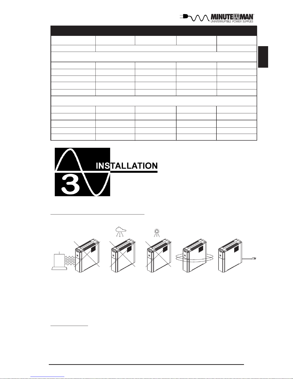
This UPS series is intended to be install in a temperature controlled environment
that is free of conductive contaminants. Avoid locations near heating devices, water
or excessive humidity, or where the UPS is exposed to direct sunlight. Select a
location which will provide good air circulation for the UPS at all times. Route power
cords so they cannot be walked on or damaged.
INST ALLATION
Be sure to read the installation placement and all the cautions before installing the
UPS. Place the UPS in the final desired location and complete the rest of the
installation procedure. These UPSs are shipped with the internal batteries disconnected. The batteries must be connected before putting these UPSs into service.
See the Connecting The Batteries procedure to connect the batteries.
Low Battery
Green LED
Short/Fault Mode
Overload
AC Mode
Over-Bat/Bat Fault
Off
Overload
Normal
Self low Battery
Buck
Boost
Normal
Self-Test
UPS Status
Status LED and Alarm Table
Battery Mode
Yellow LED Red LED Alarm
Off
Off
Off
Off
OffOff
Off
Off
Off
Off
Off
Off
Off
Off
Off
Off
Off Off
Off
On
On
On Continuous
On
On
On
1-Beep/5-sec
1-Blink/1.5sec
2-Blinks/sec
2-Blinks/sec
2-Blinks/sec
2-Blinks/sec
2-Blinks/sec
2-Blinks/sec
1-Beep/5-sec
3-Beeps/30-sec
2-Beeps/sec
2-Beeps/5-sec
2-Beeps/sec
3-Beeps/5-sec
All LEDs cycle (each LED Blinks 1/1.5seconds)
Page 9
8
English
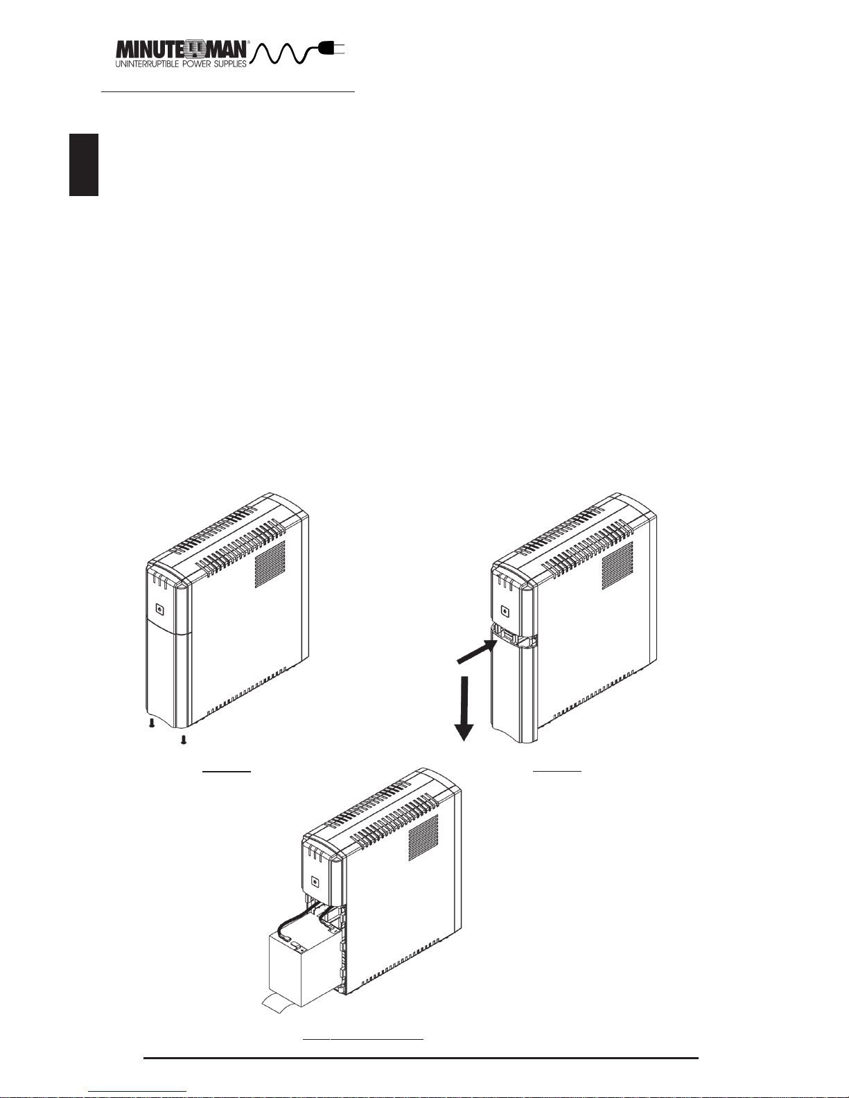
CONNECTING THE BA TTERIES
(QUALIFIED SERVICE PERSONNEL ONLY)
Please read all of the WARNINGS and CAUTIONS before attempting to connect the
batteries.
1. Remove the UPS from the shipping box and set on a table or a bench top.
2. Remove the retaining screws from the bottom of the front panel of the UPS.
(FIG. 1)
3. Gently push the top of the battery compartment cover inward and then slide the
battery compartment cover off the UPS. (FIG. 2)
4. For the ETR500/700: Grasp the battery pull tab and gently pull the battery out far
enough to connect the battery positive (Red) wire. (FIG. 3)
NOTE: The ETR1000/1500 have Red Anderson connectors to connect the battery.
5. Verify proper polarity. For the ETR500/700: Connect the battery positive (Red)
wire to the battery positive (Red) terminal. For the ETR1000/1500: Connect the
two Red Anderson connectors together. (FIG. 3)
NOTE: Some sparking might occur, this is normal.
6. Re-install the battery compartment cover onto the UPS.
WARNING: DO NOT pinch the battery wires with battery comp artment cover.
7. Re-install the battery compartment cover retaining screws.
8. Continue with the rest of the Installation.
FIG. 3: ETR500
FIG. 1
FIG. 2
Page 10

9
English
CHARGING THE BATTERY
The UPS will charge the internal batteries whenever the UPS is connected to
an AC source and there is an acceptable AC voltage present (90 - 150VAC). It
is recommended that the UPS's batteries be charged for a minimum of 4 hours
before use. The UPS may be used immediately, however, the “On Battery”
runtime maybe less than normally expected. NOTE: If the UPS is going to be
out of service or stored for a prolonged period of time, the batteries must be
recharged for at least twenty-four hours every ninety days.
USB COMMUNICATIONS PORT CONNECTION (OPTIONAL)
The Power Monitoring Software can be used with the UPS. Use the interface
cable that comes with the UPS. Connect one end of the USB cable to the USB
communications port on the rear panel of the UPS. Connect the other end of
the USB cable to the device that will be monitoring/controlling the UPS. NOTE:
Connecting to the communications port is optional. The UPS works properly
without this connection.
CONNECTING THE UPS TO AN AC SOURCE
CAUTION - To reduce the risk of fire, connect only to a circuit provided with 20
amperes maximum branch circuit over-current protection in accordance with
the National Electric Code, ANSI/NFPA 70. Plug the UPS into a two pole, three
wire, grounded receptacle only. Do not use extension cords, adapter plugs, or
surge strips.
CONNECTING YOUR EQUIPMENT
Plug the mission critical equipment into the Battery Backup & Surge output
receptacles on the rear panel of the UPS. Plug the non-critical equipment into
the Surge Only output receptacles on the rear panel of the UPS. Do not use
extension cords, adapter plugs or surge strips on the output of the UPS. Ensure that you do not exceed the maximum output rating of the UPS (refer to the
information label or the electrical specifications in this manual).
CAUTION! DO NOT connect a laser printer to the output receptacles on the UPS.
FIG. 3: ETR700 FIG. 3: ETR1000/1500
Page 11

10
English
SYSTEM OVERVIEW
This Line-Interactive UPS protects computers, internetworking, and telecommunications equipment from blackouts, brownouts, overvoltages, and surges.
The A VR function continuously corrects the voltages, in-between the brownout
and overvoltage transfer points (90 - 150V AC), to a safe usable level. When the
UPS is operating in the A VR mode the audible alarm will remain silent and the
AC Mode indicator will blink. During normal AC operation, the UPS will quietly
and confidently protect your system from power anomalies.
The UPS will charge the batteries with the UPS in the on or off position when
the UPS is plugged into the wall outlet and there is an acceptable AC volt age
present (90 - 150V AC). When a blackout, brownout, or an overvoltage condition
occurs; the UPS will transfer to the battery mode, the On Battery indicator will
illuminate and the audible alarm will sound once every five seconds indicating
that the commercial power is lost or unacceptable. When the commercial
power returns or is at an acceptable level, the UPS will automatically transfer
back to the AC normal mode and start recharging the batteries. During an
extended outage when there is approximately two minutes of backup time remaining the audible alarm will sound twice every five seconds. This Low Battery Warning is letting the user know that they should save all open files and
turn off their computer . When the batteries reach the predetermined level the
UPS will automatically shutdown protecting the batteries from over discharging. Once the commercial power returns the UPS will automatically restart,
providing safe usable power to the connected equipment and start recharging
the batteries.
PHONE/F AX/MODEM/NETWORK PROTECTION CONNECTION (OPTIONAL)
Connect a 10/100 Base-T network, single line phone, fax or modem line to the
RJ-1 1/45 modular connectors on the rear p anel of the UPS. This connection
will require another length of telephone cable (provided) or network cable. The
cable coming from the telephone service or network system is connected to the
port marked “IN”. The equipment to be protected is connected to the port
marked "OUT". NOTE: Connecting to the phone/fax/modem/network modular
connectors is optional. The UPS works properly without this connection.
Page 12

11
English
USB COMMUNICA TIONS PORT
The USB communications protocol is HID. The HID USB driver comes standard in the Windows OS. Simply plug the USB cable into the UPS and the
computer then follow the prompts on the screen.
WEAK/BAD BA TTERY
The UPS automatically tests the battery’s condition and will illuminate the Bad
Battery/Overload/Fault LED and sound the alarm. This alarm will be repeated
until the batteries pass a self test. If the battery is weak, bad or disconnected,
the Bad Battery/Overload/Fault LED will illuminate and the alarm will beep three
times every thirty seconds until the battery is reconnected or replaced. It is
recommended that the UPS be allowed to charge overnight before performing a
battery test to confirm a Weak/Bad Battery condition.
OVERLOAD
When the amount of load attached to the UPS exceeds its power rating, the
Bad Battery/Overload/Fault LED will illuminate and the UPS will sound 1 beep
every half second (AC and Battery modes). This alarm will remain on until the
excess load is removed or the UPS’s self protection circuit shuts the UPS
down.
POWER MONITORING SOFTW ARE
The UPS comes with power monitoring software. See the software CD for the
installation of the power monitoring software.
ALARMS
ON BA TTERY
When the UPS is operating on the batteries, the On Battery LED will illuminate
and the audible alarm will sound once every five seconds. The alarm will stop
once the UPS returns to the AC normal mode.
LOW BA TTERY WARNING
The UPS will sound two beeps every five seconds when the battery reserve runs
low . This condition will continue until AC returns or the UPS shut s down from
battery exhaustion.
UPS FAULT
When the UPS detects a hardware fault, the Bad Battery/Overload/Fault LED
will illuminate and the UPS will sound a constant alarm. The fault condition, in
some instances, may be reset by turning the UPS off and then on.
TURNING THE UNIT ON/OFF
On / Off Button
Press and release the On/Off Button to turn the UPS on. The alarm will sound
one beep and the LEDs will cycle while the UPS performs a five second internal
self-test. Once the UPS has passed its internal self-test the UPS will provide
an output and the load will be powered. Press and release the On/Off Button
to turn the UPS off. The UPS will continue to charge the batteries whenever it
is plugged into a wall outlet and there is an acceptable AC voltage present.
Page 13

12
English
Possible Cause
Symptom
What To Do
Press and release the On/Off
button to start UPS
On/Off/ button not pressed
UPS will not turn on
Reset circuit breaker by
pressing the plunger back in.
If the AC circuit breaker trips
after UPS starts up, reduce
the load on the UPS
UPS operates in
battery mode only,
even though there
is normal AC
present
Input AC circuit breaker is
tripped
UPS has detected an
internal fault
Call for service
Fault LED is
illuminated
The AC Mode LED
is illuminated, but
there is no output
Disconnect the computer
cable from the UPS and press
the On button. If UPS works
normally, the software has
control of the UPS
The UPS is being
controlled via its
communications port
The batteries may be
weak or at the end of useful service life
Charge the batteries for 8hours and retest. If the runtime
is still less than expected, the
batteries may need to be
replaced, even though the
Weak/Bad Battery LED is not
illuminated
UPS does not
provide expected
runtime
Bad Battery LED is
illuminated
Overload LED is
illuminated
Loose connections at the
batteries, Weak batteries,
Bad batteries
The load has exceeded the
UPS's capacity
Check battery connections,
charge the batteries for 8hours, replace the batteries
Check the specifications (see
section 8). Remove part of
the load
The AC Mode LED is
blinking once every
second and the audible
alarm is silent
The AC Mode LED is
blinking twice every
second and the audible
alarm is silent
The UPS is operating in
the Boost Mode
The UPS is operating in
the Buck Mode
The UPS is performing its
intended function
The UPS is performing its
intended function
Page 14

13
English
REPLACING THE BATTERY
W ARNING!
This UPS contains potentially hazardous voltages. Do not attempt to disassemble the UPS beyond the battery replacement
procedure. This UPS contains no user serviceable parts. Repairs and battery replacement must be performed by QUALIFIED
SERVICE PERSONNEL ONL Y.
Do not open or mutilate batteries. Released electrolyte is harmful
to the skin and eyes and may be toxic.
CAUTION:
(QUALIFIED SERVICE PERSONNEL ONL Y)
CAUTION:
Do not dispose of batteries in a fire. The batteries may explode.
The batteries in this UPS are recyclable. Dispose of the batteries properly . The batteries contain lead and pose a hazard to the
environment and human health if not disposed of properly . Refer
to local codes for proper disposal requirements or return the
battery to the supplier .
Although the battery system voltage is only 12VDC and 24VDC
the battery system can still present a risk of electrical shock.
These batteries produce sufficient current to burn wire or tools
very rapidly , producing molten metal. Observe these precautions
when replacing the batteries:
1. Remove watches, rings, or other metal objects.
2. Use hand tools with insulated handles.
3. Wear protective eye gear (goggles), rubber gloves and boots.
4. Do not lay tools or other metal parts on top of batteries.
5. Disconnect the charging source prior to connecting or disco nnecting the battery terminals.
6. Determine if the battery is inadvertently grounded. If the bat tery is, remove the source of the grounding. Contact with any
part of a grounded battery can result in an electrical shock.
The likelihood of such shock will be reduced, if such grounds
are removed during installation and maintenance.
CAUTION:
Please read all of the WARNINGS and CAUTIONS before attempting to service
the batteries.
Page 15

14
English
BA TTER Y REPLACEMENT PROCEDURE
PLEASE READ THE CAUTIONS AND WARNINGS BEFORE ATTEMPTING
TO REPLACE THE BATTERIES
Hot-swappable batteries mean that the batteries can be replaced without powering
down the whole UPS system.
NOTE: If there is a power interruption while replacing the hot-swappable batteries,
with the UPS on, the load will not be backed up. To hot-swap the batteries start with
step number 6.
1. Turn off the equipment that is plugged into the output receptacles of the UPS.
2. Press and release the On/Off Button to turn the UPS off.
3. Unplug the UPS's power cord from the AC wall outlet.
4. Unplug the equipment from the output receptacles of the UPS.
5. Unplug the computer interface cable from the the UPS.
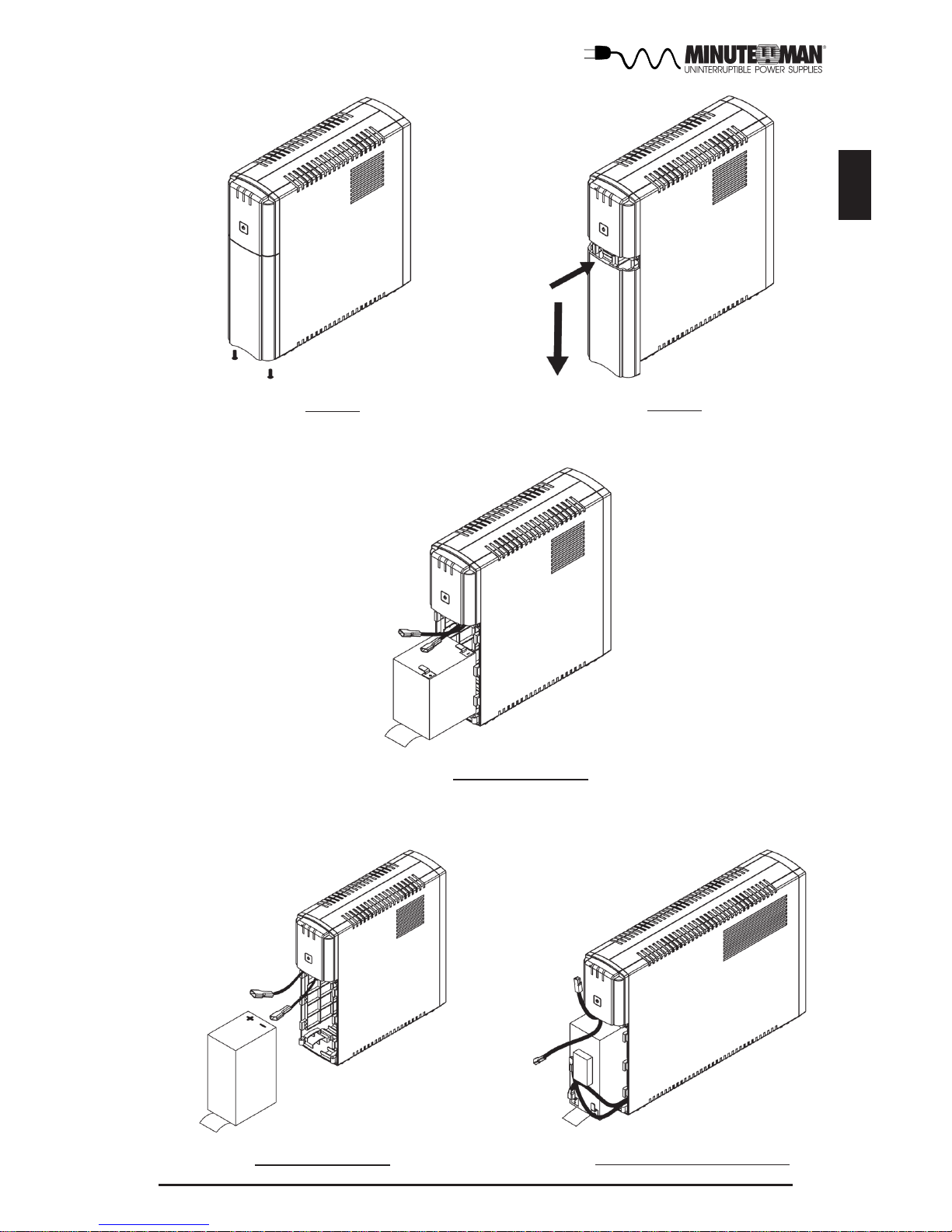
6. Remove the retaining screws from the bottom of the front panel of the UPS.
(FIG. 1)
7. Gently push the top of the battery compartment cover inward and then slide the
battery compartment cover off the UPS. (FIG. 2)
8. For the ETR500/700: Grasp the battery pull tab and gently pull the battery out far
enough to disconnect the battery positive (Red) wire. (FIG. 3)
NOTE: The ETR1000/1500 have Red Anderson connectors to connect the battery.
9. Disconnect the battery negative (Black) wire. (FIG. 3)
NOTE: DO NOT short the battery wires together .
10. Remove the battery and set aside.
NOTE: Orient the new battery in the same direction as the original battery.
11. Place the new battery close enough to connect the battery wires.
12. Connect the battery negative (Black) wire to the battery negative terminal.
13. For the ETR500/700: Connect the battery positive (Red) wire to the battery posi tive terminal. For the ETR1000/1500: Connect the Red Anderson connectors
together
NOTE: Some sparking might occur, this is normal.
14. Install the new battery into the UPS.
15. Re-install the battery compartment cover onto the UPS.
W ARNING: DO NOT pinch the battery wires with battery comp artment cover.
16. Re-install the battery compartment cover retaining screws.
17. Properly dispose of the old batteries at an appropriate recycling facility or return
them to the supplier in the packing material for the new batteries.
18. The UPS is now ready for normal operation.
Battery Qty/Rating
ETR1500
ETR1500p15
2-12V9Ah
Model #
Replace batteries with the same number and type as originally installed in the UPS. These batteries have pressure operated vents.
These UPSs contain sealed non-spillable maintenance-free lead acid
batteries.
CAUTION:
CSB Part #
First Power Part #
HR1234W
FP1290
ETR500
1-12V5Ah
HR1221W
FP1245
ETR700
ETR700p15
1-12V7Ah
GP1272
FP1270
ETR1000
2-12V7Ah
GP1272
FP1270
Page 16
15
English
FIG. 1
FIG. 2
FIG. 3: ETR500
FIG. 3: ETR700
FIG. 3: ETR1000/1500
Page 17

16
English
IF THE UPS REQUIRES SERVICE
1. Use the TROUBLESHOOTING section to eliminate obvious causes.
2. V erify there are no circuit breakers tripped. A tripped circuit breaker is the
most common problem.
3. Call your dealer for assistance. If you cannot reach your dealer , or if they
cannot resolve the problem call or fax the Technical Support department at
the following numbers; V oice phone (972) 446-7363, FAX line (972) 446-901 1
or contact Minuteman UPS at [email protected].
Please have the following information available BEFORE calling the Techni-
cal Support Department.
A. Your name and address.
B. Where and when the unit was purchased.
C. All of the model information about your UPS.
D. Any information on the failure, including LEDs that may be illuminated.
E. A description of the protected equipment, including model numbers if
possible.
F. A technician will ask you for the above information and, if possible, help
solve your problem over the phone. In the event that the unit requires
factory service, the technician will issue you a Return Material Authoriza tion Number (RMA #).
G . If the UPS is under warranty, the repairs will be done at no charge. If not,
there will be a charge for repair .
4. Pack the UPS in its original packaging. If the original packaging is no longer
available, ask the Technical Support T echnician about obtaining a new set.
It is important to pack the UPS properly in order to avoid damage in transit.
Never use S tyrofoam beads for a packing material.
A. Include a letter with your name, address, day time phone number , RMA
number , a copy of your original sales receipt, and a brief description of the
problem.
5. Mark the RMA # on the outside of all packages. The factory cannot accept
any package without the RMA # marked on the outside.
6. Return the UPS by insured, prepaid carrier to:
Para Systems Inc.
MINUTEMAN UPS
1455 LeMay Drive
Carrollton, TX 75007
A TTN: RMA # _______
Page 18
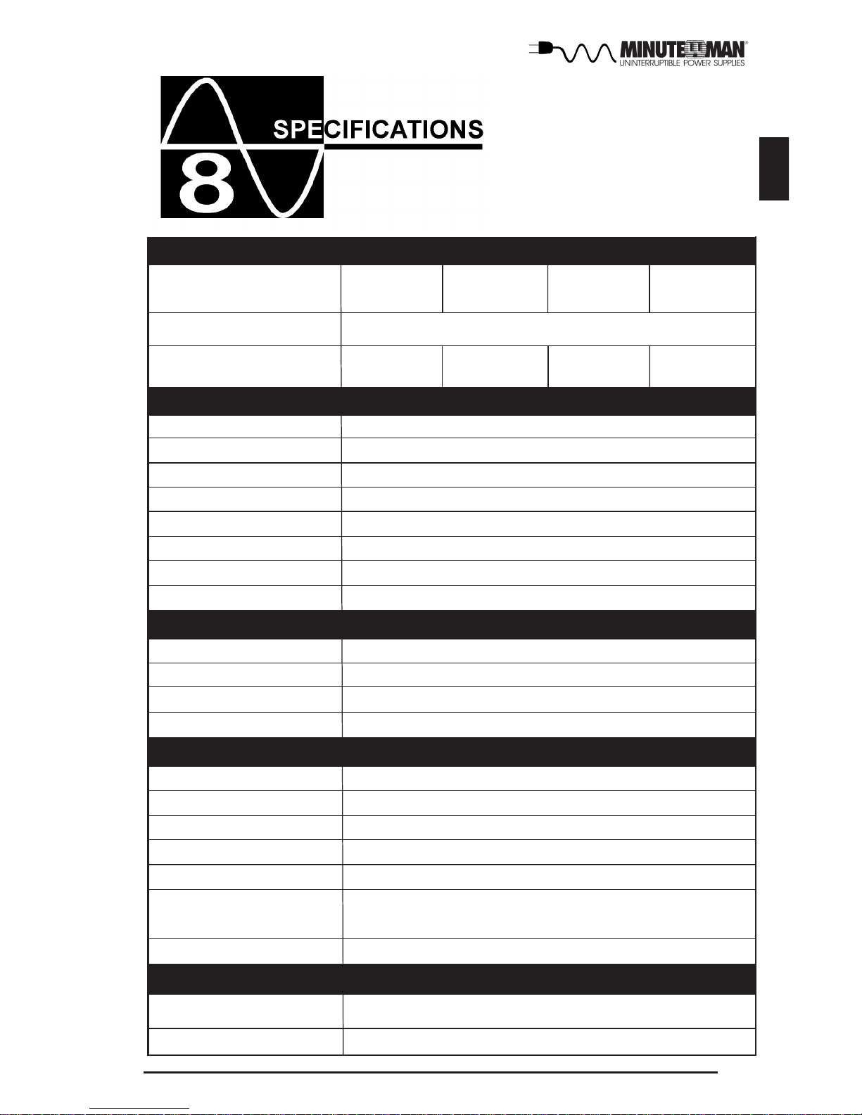
17
English
120VAC
500VA
300W
1000VA
600W
700VA
420W
Protection
Waveform Type
Over-Current, Short-Circuit Protected and Latching Shutdown
Simulated Sine Wave (Step Wave)
Frequency
50/60Hz, +/-0.5Hz (unless synchronized to utility)
Nominal Volt age
Maximum Power Capacity
6 ms T ypical
>90% (Full Load)
Resettable Circuit Breaker
50 or 60 Hz, +/-5Hz, autosensing
0 - 160VAC
90 - 150VAC
105 - 130VAC
Transfer Time
Efficiency (Line Mode)
Input Protection
Frequency Limits
Voltage Range
Acceptable Input voltage
ETR1000
ETR700
ETR700p15
ETR500
Model Number
SYSTEM SPECIFICA TIONS
Voltage Range
Topology
Line-Interactive, Simulated Sine Wave
OUTPUT NON-BA TTERY OPERA TION
INPUT
Number of Phase Single (1∅ 2W +G)
Nominal Voltage 120VAC
Low Voltage Transfer Point
90V resets to Utility Power at 94V or higher
High Voltage Transfer Point
150V resets to Utility Power at 146V or lower
Voltage Regulation 120VAC: -12.5% - +8.4%
Frequency Range 60Hz: 55 - 65Hz or 50Hz: 45 - 55Hz
OUTPUT BA TTERY OPERA TION
Voltage Regulation Nominal +/-6% (until Low Battery Warning)
Overload Capacity
110% for 10-seconds
120% Shutdown Immediately
ETR1500
ETR1500p15
1500VA
900W
REGULA TORY COMPLIANCE
Safety and Approvals
EMC Verification
UL1778, cUL (CSA 22.2 no. 107.1)
FCC Class B, CE certified
Page 19
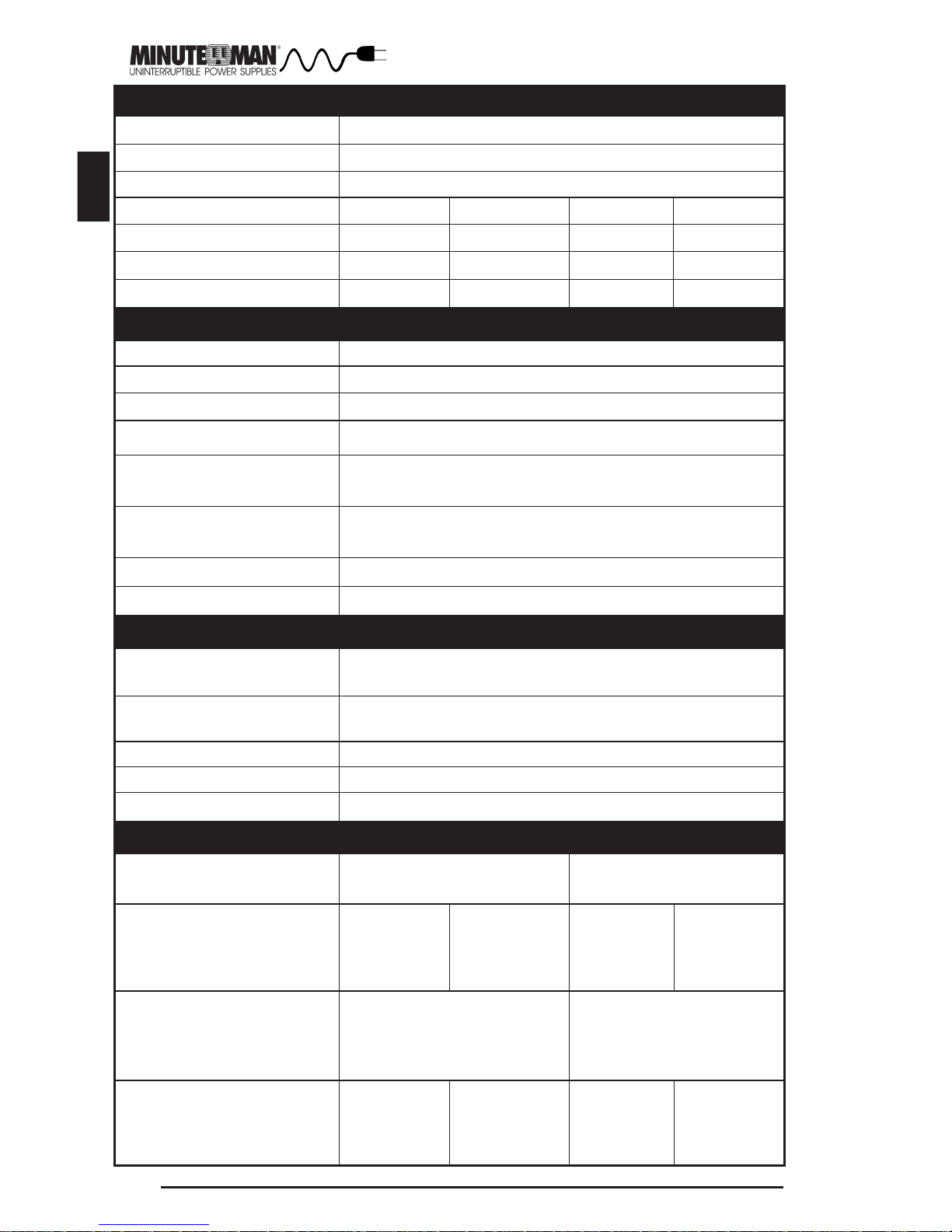
18
English
BA TTERY SYSTEM
Typical Recharge T ime
Typical Battery Life
Battery: Quantity/Rating
3-5 years, depending on discharge cycles and ambient temp
1-12V5Ah
2-12V7Ah
8-hours from total discharge
2-12V9Ah
Battery Type
Sealed, Non-Spillable, Maintenance Free, V alue Regulated Lead Acid
System Voltage
12VDC
24VDC 24VDC
Runtime: Full Load (minutes)
Runtime: Half Load (minutes)
9
2
SURGE PROTECTION AND FIL TERING
Audible Noise at 1 m (3 ft.)
10/100 Base-T surge protection let-through
(as a percentage of an applied +/-6 kV 1.2/50
us, 500 a 8/20 uS test)
T elephone line surge protection let-through
(as a percentage of an applied +/-6 kV 1.2/50
us, 500a 8/20 uS test)
Noise Filter
Surge voltage let-through (as a percentage
of an applied ANSI C62.41 Cat. A +/-6 kV)
Surge Response Time
Surge Current Capability
Surge Energy Rating 320 J
0 ns (instantaneous) normal mode; <5 ns common mode
< 5%
normal and common mode EMI/RFI suppression
<45 dBA
< 1%
< 5%
6500 Amps total
PHYSICAL
Weight - Net
(ETR700p15, ETR1500p15)
Size - Net
L X W X H
Size - Shipping
L X W X H
(ETR700p15, ETR1500p15)
Weight - Shipping
(ETR700p15, ETR1500p15)
13.23 lbs
6.0 Kgs
10.91 x 3.43 x 10.80"
277.2 x 87 x 274.4 mm
16.14 x 7.09 x 15.94"
410 x 180 x 405 mm
(16.04 x 8.19 x 15.94"
410 x 208 x 405 mm)
20.0 lbs
9.0 Kgs
(21.0 lbs
9.32 Kgs)
12VDC
1-12V7Ah
16.4 x 3.43 x 10.80"
412.5 x 87 x 274.4 mm
21.26 x 7.09 x 15.94"
540 x 180 x 405 mm
(21.26 x 8.19 x 15.94"
540 x 208 x 405 mm)
29.33 lbs
13.3 Kgs
(30.12 lbs
13.66 Kgs)
34.0 lbs
15.4 Kgs
(35.0 lbs
15.66 Kgs)
ENVIRONMENT AL
Operating/Storage Humidity
95% Non-Condensing
Storage Elevation
0 to 15,000m (0 to +50,000 ft)
Storage Temperature -15 to +45°C (+5 to +1 13°F)
Operating Temperature 0 to 40 degrees C (+32 to +104 degrees F) at
Operating Elevation 0 to 1,500m (0 to +5,000 ft)
Operating Temperature 0 to 35 degrees C (+32 to +95 degrees F) at
Operating Elevation 1501 to 3,000m (0 to +10,000 ft)
28.89 lbs
13.1 Kgs
15.44 lbs
7.0 Kgs
(16.14 lbs
7.32 Kgs)
18.0 lbs
8.0 Kgs
34.0 lbs
15.2 Kgs
11
3
14
4
10
3
Page 20

19
English
Para Systems, Inc. (Para Systems) warrants this equipment, when properly applied
and operated within specified conditions, against faulty materials (excluding the
batteries) or workmanship for a period of three years from the date of purchase.
Para Systems Inc. (Para Systems) warrants the batteries for a period of two years
from the date of purchase. For equipment sites within the United St ates and Canada,
this warranty covers repair or replacement of defective equipment at the discretion of
Para Systems. Repair will be from the nearest authorized service center. Replacement parts and warranty labor will be borne by Para Systems. For equipment located outside of the United States and Canada, Para Systems only covers faulty
parts. Para Systems products repaired or replaced pursuant to this warranty shall
be warranted for the unexpired portion of the warranty applying to the original product. This warranty applies only to the original purchaser who must have properly
registered the product within 10 days of purchase.
The warranty shall be void if (a) the equipment is damaged by the customer, is
improperly used, is subjected to an adverse operating environment, or is operated
outside the limits of its electrical specifications; (b) the equipment is repaired or
modified by anyone other than Para Systems or Para Systems approved personnel;
or (c) has been used in a manner contrary to the product’s User's Manual or other
written instructions.
Any technical advice furnished before or after delivery in regard to use or application
of Para Systems’s equipment is furnished without charge and on the basis that it
represents Para Systems’s best judgment under the circumstances, but it is used
at the recipient’s sole risk.
EXCEPT AS PROVIDED HEREIN, PARA SYSTEMS MAKES NO W ARRANTIES, EXPRESSED OR IMPLIED, INCLUDING WARRANTIES OF MERCHANTABILITY AND
FITNESS FOR A PARTICULAR PURPOSE. Some states do not permit limitation of
implied warranties; therefore, the aforesaid limitation(s) may not apply to the purchaser.
EXCEPT AS PROVIDED ABOVE, IN NO EVENT WILL PARA SYSTEMS BE LIABLE
FOR DIRECT , INDIRECT, SPECIAL, INCIDENTAL, OR CONSEQUENTIAL DAMAGES
ARISING OUT OF THE USE OF THIS PRODUCT , EVEN IF ADVISED OF THE POSSIBILITY OF SUCH DAMAGE. Specifically, Para Systems is not liable for any costs,
such as lost profits or revenue, loss of equipment, loss of use of equipment, loss of
software, loss of data, cost of substitutes, claims by third parties, or otherwise. The
sole and exclusive remedy for breach of any warranty, expressed or implied, concerning Para Systems’s products and the only obligation of Para Systems hereunder, shall be the repair or replacement of defective equipment, components, or
parts; or, at Para Systems’s option, refund of the purchase price or substitution with
an equivalent replacement product. This warranty gives you specific legal rights and
you may also have other rights which vary from state to state.
Page 21

20
English
A1. DECLARATION OF CONFORMITY
Application of Council Directive(s): 89/336/EEC, 73/23/EEC
S tandard(s) to which Conformity is declared:
Manufacturer’s Name: Para Systems, Inc. (MINUTEMAN UPS)
Manufacturer’s Address: 1455 LeMay Drive
Carrollton, Texas 75007 USA
T ype of Equipment: Uninterruptible Power Supplies (UPS)
Model No: ETR500, ETR700, ETR1000, ETR1500, ETR700p15,
ETR1500p15
I hereby declare that the equipment specified above conforms to the above
Directive(s).
Place: Carrollton, Texas, USA
Date: February 1, 2007
Robert Calhoun
(Name)
Manager Engineering
(Position)
Y ear of Manufacture: Beginning February 1, 2007
EN55022, EN55024
EN61000-6-1, EN61000-6-3
EN61000-4-5
Page 22

21
English
Notes:
Page 23

22
English
Notes:
Page 24

Page 25
Para Systems, Inc.
1455 Lemay Dr .
Carrollton, TX 75007
Phone: 1-972-446-7363
Fax: 1-972-446-9011
Internet: minutemanups.com
UPS Sizing: sizemyups.com
PN - 34000295 R1
 Loading...