

Parasound HCA-500 Owner's Manual

O W N E R ‘ S M A N U A L
Parasound HCA-500 High Current Amplifier
Congratulations on your purchase of this precision audio component and thank you for your selection of
Parasound. Your HCA-500 has been designed with the latest technology to become the heart of the finest
music systems. Its high power output is matched by an ample current capacity to drive virtually any speakers
you might select. A robust power transformer and potent power supply assure power in reserve. An ultra-fast
discrete A/AB output stage assures flawless reproduction. You have made an excellent choice.
Please take a few moments now to read these instructions thoroughly so you may fully understand the
sophisticated capabilities of your new power amplifier.
Save your carton and the styrofoam inserts for future safe transport in case you move or the unit ever
requires shipping for repair. Note, the actual printed carton is not itself strong enough for safe shipping, so it
is best if you place it into an additional outer "overcarton" before shiprnent.
Before you proceed, find the serial number which is located on the rear panel of the unit and note it here for
future reference or in case the unit is ever stolen___________________ .
Unpacking
- 1 -
WARNING: To prevent fire or shock hazard, do not expose this unit to rain or moisture.
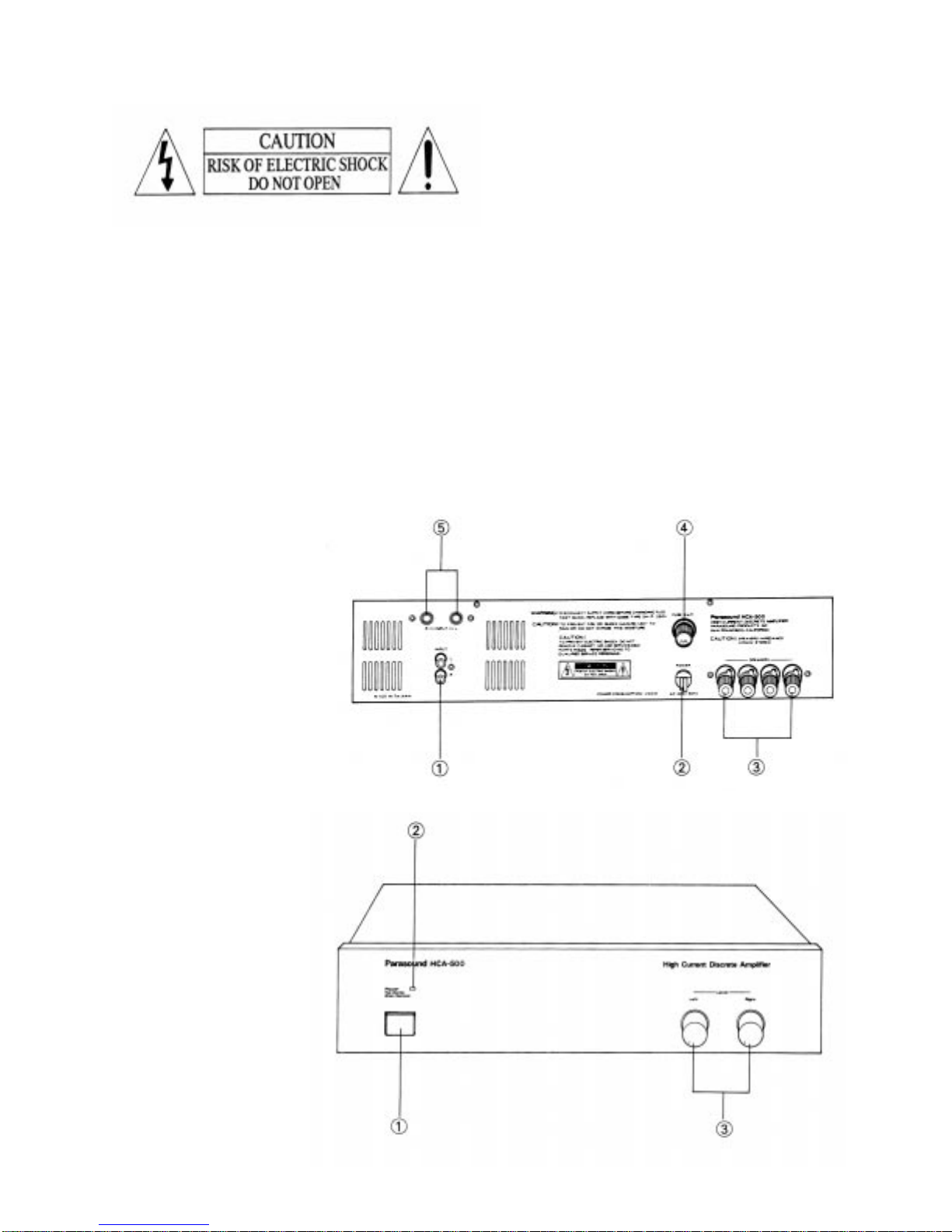
Rear Panel
1. Input Jacks (RCA type)
2. AC Power Cord
3. Speaker T erminals
4. Main Fuse
5. Input Jacks (1/4” phone jacks)
Caution: To reduce the risk of electric
shock, do not remove the top cover.
There are no user-serviceable parts
inside. Refer servicing to qualified
service personnel.
Front Panel
1. Power Switch
2. Standby-Operation LED
3. Level Controls
- 2 -
Placement of your HCA-500
Keep your Parasound HCA-500 out of direct sunlight and away from windows which could ever be left
open to let in rain. It should be placed away from heat sources such as hot air ducts or radiators; do not place
the unit directly on a pile carpet that could interfere with air flow into its bottom vent openings. If you place
the HCA-500 on the floor near your speakers, elevate it up from the pile of the carpet. If you stack your
components, it is better to place the HCA-500 above or alongside your other components; when driven hard,
the unit itself may create a little heat and disturb components stacked on top of it. If it is inside a cabinet,
allow ample ventilation. Very sensitive low level sources might pick up some hum radiated from its power
transformer .
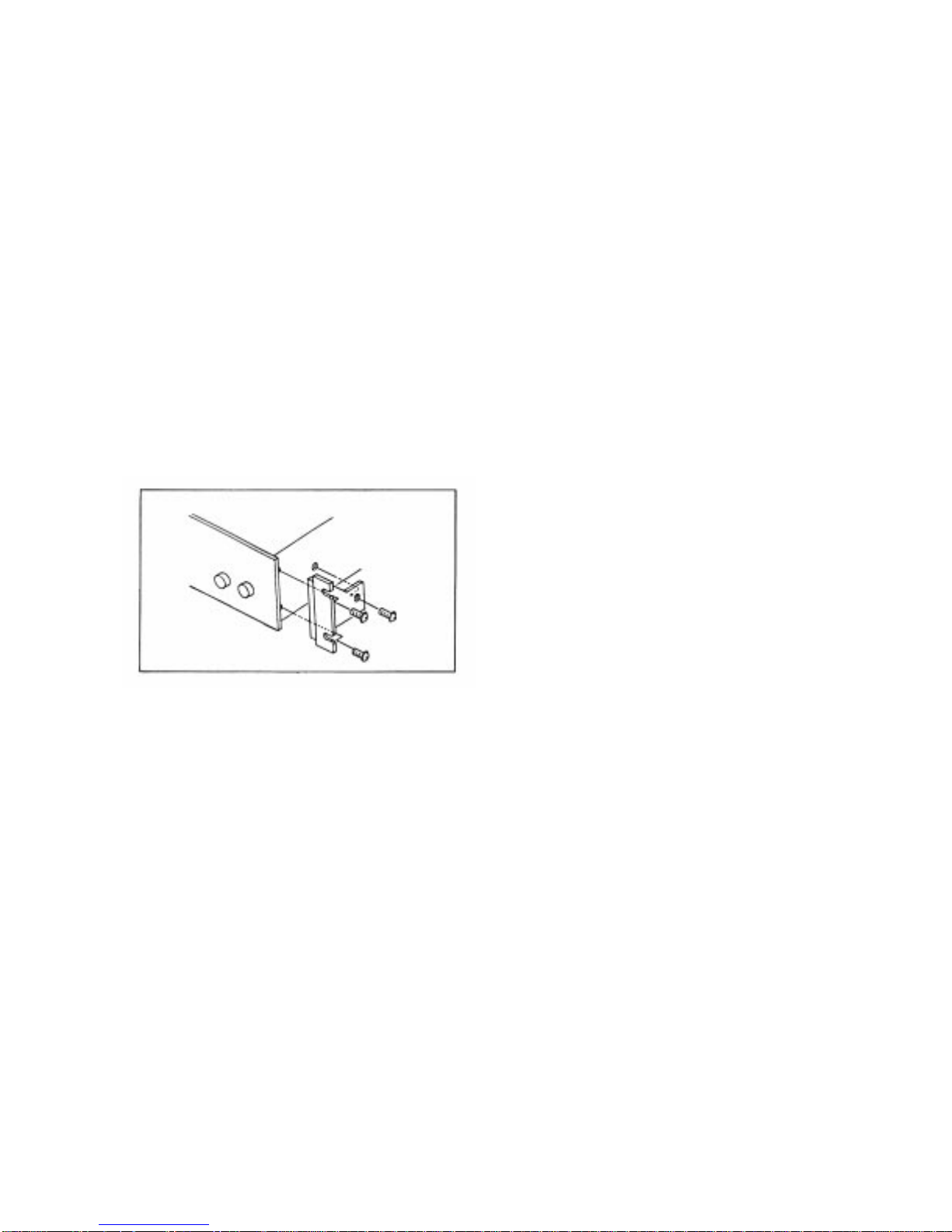
Rack Mounting the HCA-500
The HCA-500 can be mounted to a 19" rack by attaching the optional RMK-800 Rack Mount Kit as shown
below . Please note, the panel size of the HCA-500 is 3 3/4" high, which is 1/4" taller than a standard EIA 2space rack. You may find you need to drill new mounting holes in your rack to accommodate it properly.
To attach the RMK-800, first remove the
three bolts at each side of the cover - closest
to the front panel. Use the 6 longer bolts
supplied in the rack mount kit to attach both
panel extension/chassis supports.
Tighten these firmly, as they bear the full
weight of the amplifier.
(Sorry-RMK-800s are no longer available)
Making Connections
Before making any signal or speaker connections, make sure your power amplifier is turned off. When
making connections, make sure there is no strain or tension on input leads or speaker wires that could cause
them to pull loose later on.
lnput connections
In most stereo systems, you will use the gold-plated RCA jacks for the R and L channels. Make sure these
are consistent with the R and L outputs from your preamplifier.
For professional applications you can use the alternate 1/4" (6.3mm) phone jack inputs. These are also
"unbalanced" inputs, the same as the RCA jacks.
Speaker connections
You may use either bare wire or banana plugs with the HCA-500 "5-way" terminals. If you use bare wire
without spade lugs or plugs, make sure you strip only enough wire to fit into the hole that runs across the
metal shaft of the terminal. Before inserting the wir e, twist all its strands tightly to prevent strays that could
cause a short circuit between + and - terminals!
- 3 -
 Loading...