

Parasound HALO JC, HALO JC I Owner's Manual

JC 1 Amplifier
Owner’s Guide

1
THANK YOU!
Congratulations and Thank You for Choosing Parasound
Your new Parasound Halo Series JC 1 mono block power amplier represents the latest
advancements in amplier technology. The JC 1 was designed by CTC builders and it uses higher
quality parts and achieves higher performance than any amplier we’ve made since Parasound
was founded in 1981. We’re proud to offer you this exceptional audio component, knowing that it
will bring you many years of enjoyment and dependability.
Here at Parasound, we design our products to perform at a higher level of exibility and sonic
performance than you may have expected. We encourage you to read this entire manual to learn
all the features and capabilities of your new JC 1 Amplier.
If you’re eager to get up and running right away, simply follow the basic step-by-step instructions
to connect and operate the JC 1. If you want to learn more about the technical and design aspects
of your JC 1, refer to the Technically Speaking and Design Overview sections in the back of the
manual. If you run into difculties, the Troubleshooting Chart should help you quickly remedy the
problem.
We appreciate you taking the time to read these instructions and thank you for selecting
Parasound for your listening pleasure.
The Parasound Staff
Unpacking Your JC 1
Unpack your JC 1 from the shipping carton, remove the enclosed AC power cord, the small
“L” shaped metal rack mounts, and the gray control wire with a sub-mini 2.5 mm plug on each
end. (This is the trigger connection wire). While you are unpacking your new amplier, inspect
it thoroughly for possible shipping damage. If you see any, contact your Parasound dealer right
away. Be sure to save and store both the inner and outer cartons and the packing inserts for
possible future transport. To save
room for storage, you can cut the seams on the bottom of the cartons and atten them.
Keeping Records for Future Reference
Record the serial number located on the bottom of your JC 1 in the space below. Also note
your Parasound Dealer’s name and phone number. We recommend that you keep your purchase
receipt with this manual and store them both in a safe place. You may need to refer to this
information sometime in the future.
Parasound JC 1 Amplier Serial #: ____________________________________
Parasound Dealer: ___________________________________________________
Phone Number______________________________________________________
Date of Purchase: ___________________________________________________
YOU SHOULD KNOW
There is no Parasound warranty for this unit if it was not purchased from an Authorized Parasound
Dealer. Investigate any claims of warranty coverage made by unauthorized dealers very carefully
as you will need to depend entirely upon the dealer, and NOT upon Parasound. Unauthorized
dealers may lack the capability to arrange repairs of Parasound equipment. Authorized Parasound
Dealers are listed at www.parasound.com or you can call 415-397-7100 between 8:30 am and 4:30
pm Pacic time.
A missing or tampered serial number could indicate that this unit was stolen or sold by an
unauthorized dealer. You should return it to your dealer immediately for replacement or a full refund.

PLACEMENT GUIDELINES FOR YOUR JC 1
_________________________________________________________________________________
CONNECTING A STEREO PREAMPLIFIER OR A SURROUND
CONTROLLER TO THE BALANCED INPUT ON YOUR JC 1
_________________________________________________________________________________
CONNECTING A STEREO PREAMPLIFIER OR A SURROUND
CONTROLLER TO THE UNBALANCED INPUT ON YOUR JC 1
_________________________________________________________________________________
CONNECTING A SPEAKER TO YOUR JC 1
_________________________________________________________________________________
MANUAL AND AUTOMATIC TURN ON-OFF OPTIONS
_________________________________________________________________________________
CONNECTING AN EXTERNAL DC SOURCE FOR AUTOMATIC TURN ON-OFF
_________________________________________________________________________________
CONNECTING THE JC 1 TO TRIGGER ANOTHER COMPONENT
_________________________________________________________________________________
UNDERSTANDING THE INDICATORS ON THE JC 1
_________________________________________________________________________________
CONNECTING THE AC POWER CORD
_________________________________________________________________________________
MAINTAINING YOUR JC 1
_________________________________________________________________________________
TROUBLESHOOTING GUIDE
_________________________________________________________________________________
SERVICING YOUR JC 1
_________________________________________________________________________________
TECHNICALLY SPEAKING
_________________________________________________________________________________
PARASOUND JC 1 DESIGN OVERVIEW
_________________________________________________________________________________
PARASOUND JC 1 SPECIFICATIONS
_________________________________________________________________________________
1
TABLE OF CONTENTS
JC 1 Amplifier
13
12
17
15
11
10
9
8
7
5
4
2
1
3
6
PLACEMENT GUIDELINES FOR YOUR JC 1
1
Power ampliers are usually heavier and generate more heat than other components. To avoid
damage to the JC 1 or other equipment and to reduce risk of re, you must follow these guidelines:
• Place the JC 1 on a separate shelf that will adequately support its weight.
• Keep it away from heat sources such as air ducts or radiators.
• Avoid placing it on carpeting or another material that might obstruct airow into the openings
in the chassis bottom.
• Leave at least 3” of space around both sides and 6” of space above the top. The bottom
clearance can be a little less.
• Do not block the front of the JC 1 behind closed cabinet doors during use.
• Do not stack the JC 1 with other components inside a cabinet unless you use a fan to circulate
and exhaust the warm air that builds up between them.
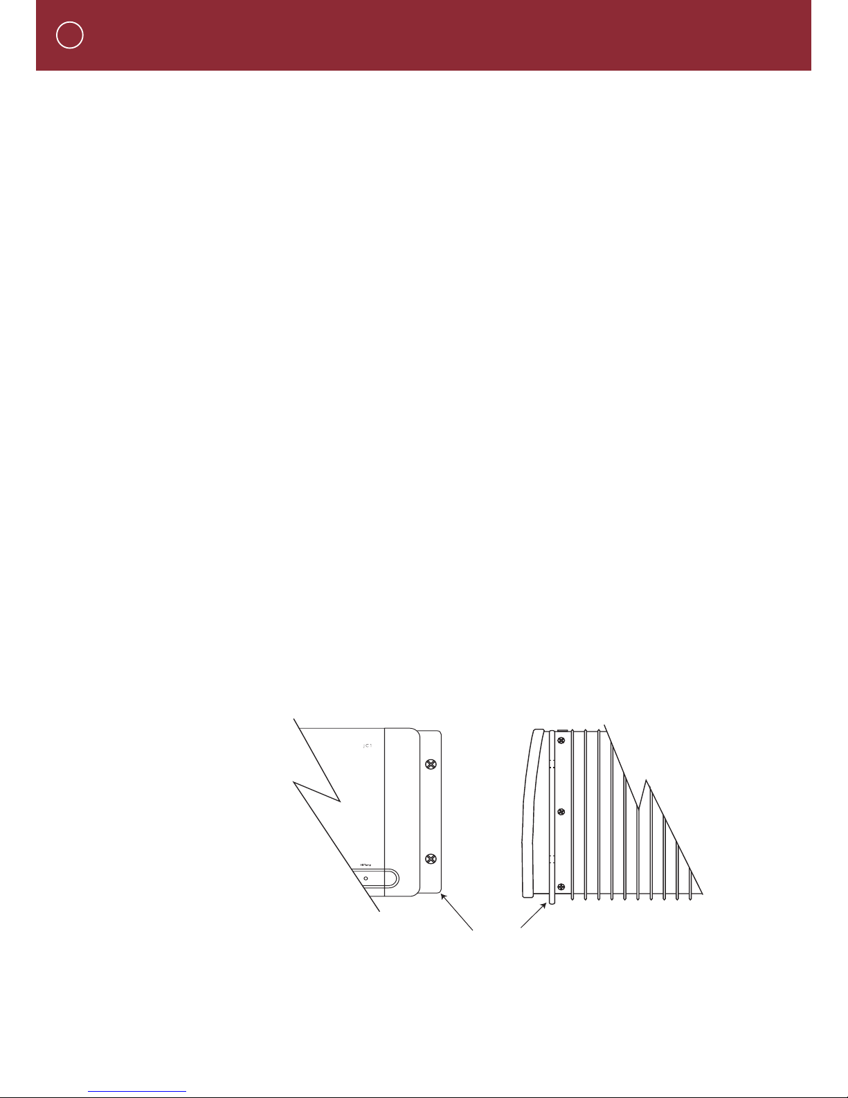
Rack Mounting Your Parasound JC 1
To mount the JC 1 into a 19” wide equipment rack, you must rst attach its Rack Mount Adapters
(provided). With its four feet removed, the JC 1 chassis and front panel height occupies four rack
spaces (7” or 176 mm). When mounting equipment below the JC 1, you will also need to allow
about 1/8” below the unit for the bottom chassis screws.
To attach the rack mount adaptors
• Remove the three shiny screws from each side of the JC 1. These are arranged vertically,
behind its front panel and in front of its rst heatsink n.
• The angled part of the brackets that attaches to the rack should be just behind the front
panel.
• Line up the holes on each rack mount adaptor with the holes on the unit and reinsert the
three screws.
• Make sure the screws holding the rack mounts are tight because they will support the entire
weight of the JC 1 when it’s installed into the equipment rack.
A single standard rack space allows 1-3/4” vertical inches in a 19-inch wide equipment rack.
This measurement standard was developed by the EIA (Electronic Industries Association) so
manufacturers of electronic components and equipment racks could build products in standardized
heights that would t in a uniform space. Please call your Parasound dealer or Parasound Technical
Services if you need additional advice about rack mounting the JC 1.
Rack Adapter Mounted on JC 1
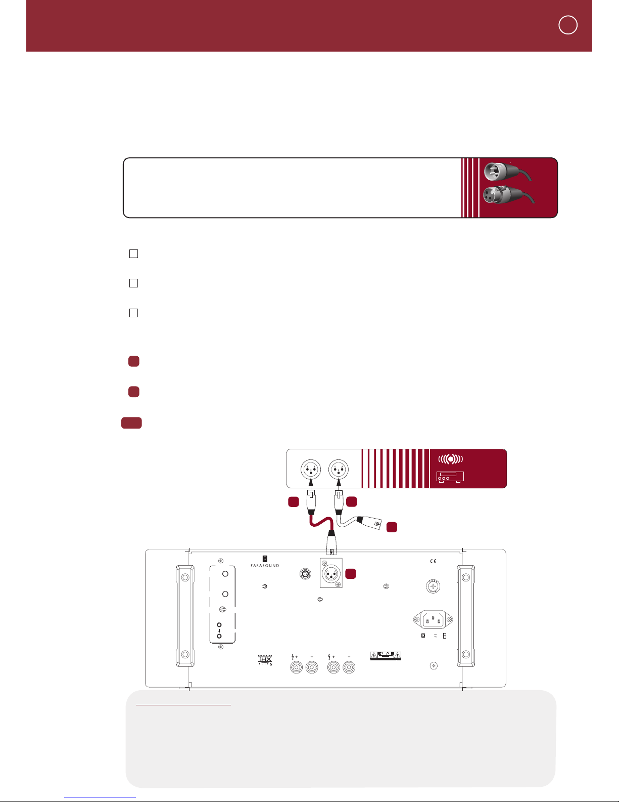
Balanced Input Jack
Balanced connections will give you the best sound in most instances. If your preamplier or
surround controller has balanced XLR output jacks, we recommend that you use them. Refer to
the Balanced and Unbalanced Lines in the Technically Speaking section for additional information
about why we recommend using balanced lines.
What You’ll Need:
• One balanced interconnect cable with XLR connectors
• A preamplier or surround controller with balanced outputs
Before Connecting
Leave the JC 1’s AC cord disconnected until you have made all other connections to prevent
any surprise burst of sound.
Make sure that all your cables are long enough so they are not strained or stretched once
they are connected.
Make sure the Select switch on the JC 1 is in its Balanced Input (right) position.
To Connect
Plug the male end of the balanced interconnect cable into the Balanced Input jack on the JC 1.
Plug the female end of this cable into the desired channel balanced output jack on your
preamplier or surround controller.
Repeat steps 1 and 2 above to connect additional JC 1s to other controller channels.
CONNECTING A STEREO PREAMPLIFIER OR A SURROUND
CONTROLLER TO THE BALANCED INPUTS ON YOUR JC 1
2
3&4
2
XLR Connectors
Male
Female
4
3
Right
Left
COMPONENTS
SUR ROUN D
SOU ND
CON TROL LER
PRE AMP
OUTPUTS
or
None
4
8
12
20 50
100
200
Auto Turn On
Delay
Seconds
Sensitivity
Input mV
Select
<
<
Select
<
<
Audio
Signal
<
Manual
12V Input
12 Volt
Trigger
Trigger
Output
JC1 Am pl ifi er
Parasound Products. Inc.
San Franscisco, CA US A
Ground
Normal
Lift
Fuse
T15A/250V-115V Area
T8A/250V-230V Area
Power Consumption: 1200W
AC 115V 60Hz
AC 230V 50Hz
CAUTION
To Prevent Electric Shock, Do Not
Remove Cover. No User-Serviceable
Parts Inside, Refer Servicing To
Qualified Service Personnel.
Bias Level
Reduced
Normal
Unbalanced Input
Balanced Input
Speaker
1
2
WARNING
To Prevent Fire Or Shock Hazard,
Do Not Expose This Unit To Rain
Or Moisture.
Manufactured under
license from Lucasfilm
Ltd. Lucasfilm and THX
are registered Trademarks
of Lucasfilm Ltd.
1
2
1
YOU SHOULD KNOW
Balanced XLR Jacks and Their Pin Conguration
The balanced input on the JC 1 uses an XLR jack that conforms to the industry standard
of: Pin 1: Ground, Pin 2: Positive (+), Pin 3: Negative (--). The balanced outputs on some
components use terminals with 3 screws instead of XLR jacks. These are compatible with the
JC 1 as long as you match the bare wires to the corresponding pins on the XLR plug: + to
pin 2, - to pin 3, and Ground to pin 1.

CONNECTING A PREAMPLIFIER OR A SURROUND
CONTROLLER TO THE UNBALANCED INPUT ON YOUR JC 1
3
1
2
RCA Plugs
Right
Left
3&4
Right
Left
COMPONENTS
SU RR OUND
SO UN D
CO NT ROLLER
PR EA MP
OUTPUTS
or
None
4
8
12
20 50
100
200
Auto Turn On
Delay
Seconds
Sensitivity
Input mV
Select
<
<
Select
<
<
Audio
Signal
<
Manual
12V Input
12 Volt
Trigger
Trigger
Output
JC 1 A mpl ifi er
Parasound Produc ts. Inc.
San Franscisco, CA US A
Ground
Normal
Lift
Fuse
T15A/250V-115V Area
T8A/250V-230V Area
Power Consumption: 1200W
AC 115V 60H z
AC 230V 50H z
CAUTION
To Prevent Electric Shock, Do Not
Remove Cover. No User-Serviceable
Parts Inside, Refer Servicing To
Qualified Service Personnel.
Bias Level
Reduced
Normal
Unbalanced Input
Balanced Input
Speaker
1
2
WARNING
To Prevent Fire Or Shock Hazard,
Do Not Expose This Unit To Rain
Or Moisture.
Manufactured under
license from Lucasfilm
Ltd. Lucasfilm and THX
are registered Trademarks
of Lucasfilm Ltd.
1
2 4
3
Unbalanced Input
Use this input if your preamplier or surround controller doesn’t have balanced output
connectors or if you simply prefer to use unbalanced connections.
What You’ll Need:
• One shielded interconnect cable with RCA plugs
• A source component with RCA output jacks
Before Connecting
Leave the AC cord on the JC 1 disconnected until you have made all other
connections to prevent any surprise burst of sound.
Make sure that all your cables are long enough so they are not strained or
stretched once they are connected.
Make sure the Select switch on the JC 1 is in its Unbalanced Input (left) position.
To Connect
Plug one end of the cable into the Unbalanced Input jack on the JC 1.
Plug the female end of this cable into the desired channel output jack on your
preamplier or surround controller.
Repeat steps 1 and 2 above to connect additional ampliers.
YOU SHOULD KNOW
Correct Speaker Polarity is Important
Polarity refers to the + and - connections. Speaker wires are coded with printing or a ridge on the
insulation on one of the leads so you know which lead was connected to the + and - terminals at the
other end. This coding will help you keep the + and - polarity consistent for all channels. Refer to Speaker
Polarity in the Technically Speaking section for additional information.
CONNECTING SPEAKERS TO YOUR JC 1
4
1
2
3&4
2
1
Speaker
None
4
8
12
20 50
100
200
Auto Turn On
Delay
Seconds
Sensitivity
Input mV
Select
<
<
Select
<
<
Audio
Signal
<
Manual
12V Input
12 Volt
Trigger
Trigger
Output
JC 1 A mpl ifi er
Parasound Produc ts. Inc.
San Franscisco, CA U SA
Ground
Normal
Lift
Fuse
T15A/250V-115V Area
T8A/250V-230V Area
Power Consumption: 1200W
AC 115V 6 0Hz
AC 230V 5 0Hz
CAUTION
To Prevent Electric Shock, Do Not
Remove Cover. No User-Serviceable
Parts Inside, Refer Servicing To
Qualified Service Personnel.
Bias Level
Reduced
Normal
Unbalanced Input
Balanced Input
Speaker
2
WARNING
To Prevent Fire Or Shock Hazard,
Do Not Expose This Unit To Rain
Or Moisture.
Manufactured under
license from Lucasfilm
Ltd. Lucasfilm and THX
are registered Trademarks
of Lucasfilm Ltd.
Stripped
AWG wire
Dual
Banana Plug
Common Speaker Connectors
Single
Banana Plug
Spade Lug
Red ususally
designates right
The GND notch
signifies ground
or speaker left
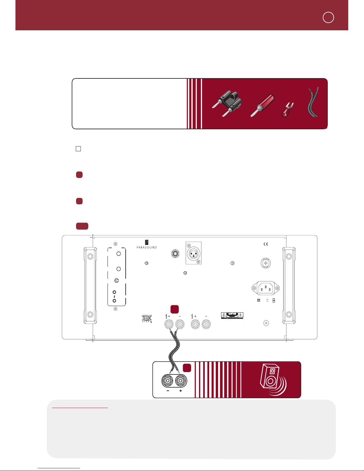
Speaker Terminals
The two ve-way binding post speaker terminals on the JC 1 are connected in parallel and accept most
speaker wire terminations including single or dual banana plugs or 1/4” spade lugs. The openings in
the terminals are too small to accommodate bare ends of the gauge speaker wire you should use.
What You’ll Need:
• Speaker wire (AWG 16 or thicker)
with banana plugs or spade lugs.
Stripped bare ends won't t terminals.
• Α Loudspeaker
Before Connecting
Remove power to all the components in your audio system.
To Connect
Connect the wire with the ridge or other marking to either red + (positive) speaker terminal
on the JC 1. Connect the wire without the ridge or other marking to the corresponding black
-- (negative) speaker terminal on the JC 1.
Insert the other end of the wire with the ridge or other marking into the red + (positive)
terminal on the speaker. Insert the wire without the ridge or other marking into the black -(negative) terminal on the speaker.
Repeat steps 1 and 2 with the other JC 1 speaker terminal to bi-wire your speaker.
 Loading...