

O W N E R ' S M A N U A L
D/AC-2000 Ultra Digital to Analog Converter
Congratulations on the purchase of this precision audio component and thank you for your selection of
Parasound. Your new D/AC-2000 features a state-of-the-art 20 bit D20400A dual digital to analog
converter and custom AES 21 digital interface receiver designed and manufactured by UltraAnalog, Inc. The
D/AC-2000 also incorporates the High Definition Compatible Digital PMD-100 HDCD process decoder
developed by Pacific Microsonics. This decoder performs precise decoding of HDCD encoded recordings
and also functions as a superb digital filter that will enhance the sonic quality of non-HDCD encoded
recordings.
Please take a few moments to read these instructions so you may fully understand how to maximize the
performance capabilities of your new digital to analog converter.
HDHD
o
P
Power
D/AC-2000 Ultra Digital/Analog ConverterD/AC-2000 Ultra Digital/Analog Converter
rity
la
o
Polarity
w
2
32kHz
3
z
H
k
.1
4
44.1kHz
4
z
H
k
8
48kHz
4
z
H
k
D
C
D
HDCD
H
y
c
n
e
u
q
re
F
g
lin
p
m
a
S
Sampling Frequency
r
e
P
Invert
In
e
v
rt
h
p
m
-E
e
D
De-Emphasis
is
s
a
l
a
k
A
s
o
Toslink
T
AES/EBU
lin
p
O
T
S
ST Optical
tic
l
ia
x
a
o
Coaxial
C
U
B
/E
S
E
Unpacking and Placement
Open the carton of your D/AC-2000 carefully and inspect the unit for possible shipping damage. Report any
damage to your dealer immediately. You will find the detachable AC line cord packed separately inside the
carton.
Save your plastic bag, inserts, and carton. You may need these later for transporting the D/AC-2000 or for
shipment in the event it ever requires factory service. Record the serial number (on rear panel) here for future
reference: ____________________
Place your D/AC-2000 as close as possible to your digital source. Keep it out of direct sunlight, and away
from heat sources such as a hot air vent or radiator. If you are stacking your components, avoid placing your
D/AC-2000 on top of heat producing components, such as power amplifiers or tube-type preamplifiers.
Keep it as far away from your tuner or receiver as possible to avoid RF interference.
-1-
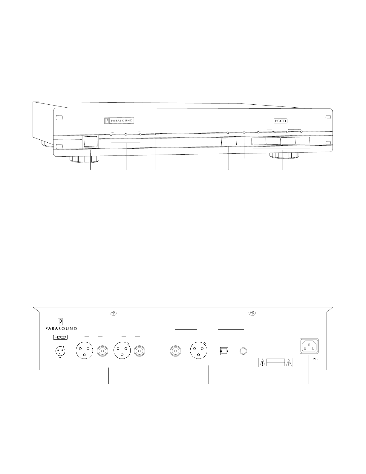
D/AC-2000 Front and Rear Panel Drawings
pling Frequency
am
er
Pow
Power Switch Sampling
S
z
44.1kH
32kHz
Frequency
Indicators
Figure #1 D/AC-2000 Front Panel Controls
D/AC-2000 Ultra Digital/Analog Converter
olarity
P
Invert
48kHz
CD
D
H
De-emphasis
HDCD
Indicator
Polarity
Invert
Switch
phasis
m
De-E
Indicator
ST O
ptical
Digital Input
Toslink
Digital Selection
ES/EB
A
Switches
U
Coaxial
12
3
PARASOUND D/AC-2000
Ultra Digital to Analog Converter
Parasound Products, Inc.
San Francisco, CA. U.S.A
Made in U.S.A.
CAUTION:
TO PREVENT ELECTRIC SHOCK,
DO NOT REMOVE COVER.
NO USER SERVICEABLE PARTS INSIDE.
REFER SERVICING TO QUALIFIED
SERVICE PERSONNEL.
CAUTION
RISK OF ELECTRIC SHOCK
DO NOT OPEN
AC 120V 60 Hz
Power Consumption: 20W
Left
Analog Outputs
Right
AES/EBU ST OpticalCoaxial
Digital Inputs
Toslink
+Ground
Bal UnbalBal Unbal
Analog Output Connectors Digital Input Connectors AC Cord Connector
Figure #2 D/AC-2000 Rear Panel Connections
-2-

Connecting Your D/AC-2000
When you make connections, be careful to avoid tension on digital and audio interconnects that might
cause damage to the connectors or cause them to pull loose. Do not bend either coaxial or optical digital
cables at an angle, this could permanently damage them. Be sure to turn off the power of your preamplifier
and power amplifier while making connections. As an additional safeguard, turn your preamplifier’s
volume control to minimum.
Digital Inputs
Your D/AC-2000 has four digital inputs: Coaxial, AES/EBU, ST Optical, and TOSlink. It is possible to
connect four separate digital sources to your D/AC-2000 and select among them from the front panel.
However, radiation from unused digital inputs may “contaminate” the sound of the selected input source.
If you have more than one digital source connected, make sure you turn off the power of the unused
source until you are ready to listen to it.
Coaxial: RCA Connector - 75
Ω Ω
Ω Unbalanced
Ω Ω
75 Ω coaxial output connections are provided on many high quality CD players. You should use only
good quality cables which have been designed for digital data transmission such as the Stereophile
recommended Parasound DataBridge. Cables designed for audio frequencies are not suitable for digital
signals and will not give you satisfactory results.
AES/EBU: XLR Connector - 110
Ω Ω
Ω Balanced
Ω Ω
AES/EBU (Audio Engineering Society/European Broadcast Union) 110 Ω balanced connections have
become the standard digital connection for professional digital audio equipment and are becoming
increasingly popular with high-end consumer equipment. AES/EBU connections are thought to be
superior to coaxial, TOSlink, and even ST connections because of their inherent noise rejection capability.
When you use the AES/EBU connection, be sure to use one designed for digital transmission such as the
recommended Parasound Balanced DataBridge. Cables designed for audio frequencies are not suitable
and will not give you satisfactory results.
Optical: ST Fiber Optic
The ST module employs the AT&T data transmission standard. ST fiber optic connections are considered
by some to be superior to either TOSlink or coaxial connection for data transmission. Use care when
connecting the ST connector to the D/AC-2000. ST connectors are more fragile than other connectors.
Pay special attention to the guide pins when making an ST connection; never try to force the connector.
Optical: TOSlink Fiber Optic
TOSlink fiber optic connections are also popular and are found on most high-quality video laser disc
players as well as older CD players and CD transports. Your dealer can assist you in selecting an
appropriate optical cable with TOSlink connectors.
-3-
 Loading...