

Page 1

A
B
Power
M o d e l 2 1 2 5 T w o C h a n n e l A m p l i f i e r
Protect Hi Temp
L
R
Two Channel Power Amplifi er
Page 2

IMPORTANT SAFETY INSTRUCTIONS
The lightning flash with the arrowhead symbol within an equilateral triangle is intended to alert
the user to the presence of “dangerous voltage” inside the product that may constitute a risk
of electric shock.
The exclamation point within an equilateral triangle is intended to alert the user to the presence
of important operating and maintenance instructions in the literature accompanying the product.
TO REDUCE THE RISK OF ELECTRIC SHOCK, DO NOT REMOVE COVER. NO USER-SERVICEABLE
— Read all the safety and operating instructions before operating this product.
— Retain safety and operating instructions for future reference.
3.
— Adhere to all warnings on the product and in the operating instructions.
4.
— Follow all operating and use instructions.
Cleaning
— Unplug this product from the wall outlet before cleaning. Use a damp cloth for cleaning.
6.
Attachments
— Do not use attachments that are not recommended by the product manufacturer;
they may be hazardous.
7.
Water and Moisture
— Do not use this product near water.
8.
Accessories
— Do not place this product on an unstable cart or stand. The product may fall, causing
9.
Ventilation
— Slots and openings in the cabinet are provided for ventilation to ensure reliable opera-
tion of the product and to protect it from overheating. These openings must not be blocked or
covered. This product should not be placed in a built-in installation such as a bookcase or rack unless
— Operate this product only from the type of power source indicated on the label.
company. This product is equipped with a three-prong grounding plug. This plug will only fit into a
grounding power outlet. If you are unable to insert the plug into the outlet, contact your electrician
to replace your obsolete outlet. Do not defeat the safety purpose of the grounding plug.
— Power supply cords should be routed so that they are not likely to be
walked on or pinched by items placed upon or against them.
— Unplug the unit from the wall outlet for added protection during a lightning storm
and when it is left unattended and unused for long periods of time. This will prevent damage to the
Overloading
— Do not overload wall outlets or extension cords. This can result in a fire or electric shock.
— Never push objects of any kind into this product through any openings;
they may touch dangerous voltage points or short out parts that could result in fire or electric shock.
Servicing
— Do not attempt to repair or service this product yourself. Opening or removing covers may
expose you to dangerous voltage and other hazards. Refer all servicing to qualified service personnel.
— Unplug this product from the wall outlet and refer servicing to quali-
fied service personnel under the following conditions:
a)
If the power-supply cord or plug is damaged.
b)
If liquid has been spilled into the product.
c)
If the product has been exposed to rain or water.
d)
e)
If the product has
f)
If the product exhibits a distinct change in performance.
— When replacement parts are required, be sure the service technician has used
tric shock, and other hazards.
Safety Check
— Upon completion of any service or repairs to this product, ask the service technician
to perform safety checks to determine that the product is in proper operating condition.
20.
Wall or Ceiling Mounting
— Mount the product to a wall or ceiling only as recommended.
— The product should be situated away from heat sources such as radiators, heat registers,
stoves, and other products (including amplifiers) that produce heat.
Page 3

TABLE OF CONTENTS
. . . . . . . . . . . . . . . . . . . . . . . . . . . . . . . . . . . . . . . . . .
2
. . . . . . . . . . . . . . . . . . . . . . . . . . . . . . . . . . . . . . . . . . .
. . . . . . . . . . . . . . . . . . . . . . . . . . . . . . . . . . .
. . . . . . . . . . . . . . . . . . . . . . . . . . . . . . . . . . . . . . . .
Level Knobs
. . . . . . . . . . . . . . . . . . . . . . . . . . . . . . . . . . . . . . . . . . . . . . . . .
High Pass Filter Switch
. . . . . . . . . . . . . . . . . . . . . . . . . . . . . . . . . . . . . . . . . .
Speaker Connections
. . . . . . . . . . . . . . . . . . . . . . . . . . . . . . . . . . . . . . . . . . .
Bridging Switch: Stereo - Mono
Mono Input
Speaker Connections
Load Impedance Switch
Auto Turn On
Sensitivity Adjust Knob
. . . . . . . . . . . . . . . . . . . . . . . . . . . . . . . . . . . . . . . . . .
Ground Switch
. . . . . . . . . . . . . . . . . . . . . . . . . . . . . . . . . . . . . . . . . . . . . . .
. . . . . . . . . . . . . . . . . . . . . . . . . . . . . . . . . . . . . . . . .
. . . . . . . . . . . . . . . . . . . . . . . . . . . . . . . . . . . . . . .
10
Are You Having Difficulty?
. . . . . . . . . . . . . . . . . . . . . . . . . . . . . . . . . . . . . . . . .
13
1
Page 4
2
The Parasound Model 2125 is the latest generation of popular and proven audio power amplifi-
a new standard for audio performance, user-friendliness and utility in custom installations.
The versatility of the Model 2125 allows many connection and configuration options, so please
Detachable AC power cord
Trigger wire with a 2.5 mm sub-mini plug at both ends
Trigger wire adapter for a 3.5mm mini jack
of shipping damage. Save the carton and packing inserts in case you move or in the event you
OWNERSHIP REFERENCE INFORMATION
/
/
Address:
)
INTRODUCTION
Page 5
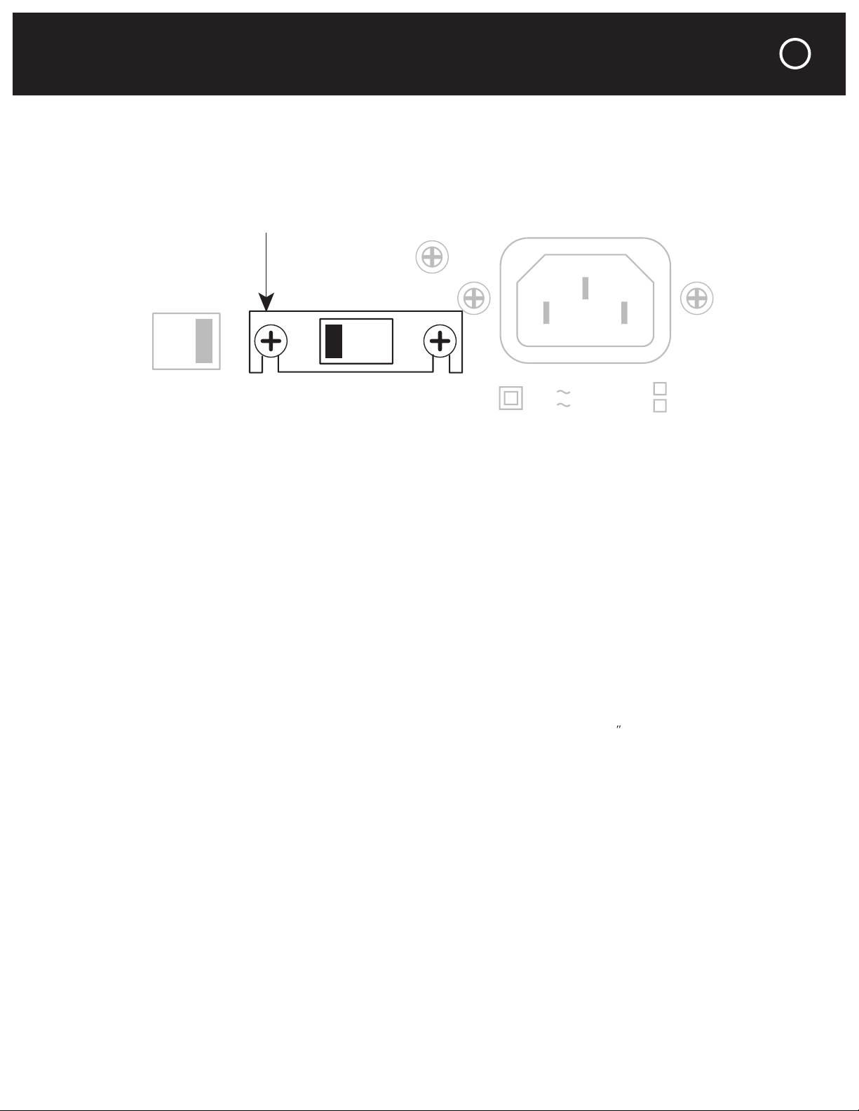
AC VOLTAGE, INSTALLATION AND RACK MOUNTING
This switch is found on the chassis rear panel. The 115V position of this switch is correct for
and before you install it. The unit may be seriously damaged if this switch is set incorrectly.
You should never install the Model 2125 in an unventilated equipment cabinet or compartment
adequately in a cabinet or enclosure whose front and back sides are open; pockets of intense
to avoid crowding or stacking the Model 2125 tightly between other components. A ventilation
fan is also recommended where other equipment must be mounted close to the Model 2125.
ventilation holes in its chassis bottom.
The Model 2125 front panel occupies only two rack spaces in a standard 19
equipment rack.
separately). We recommend that you use the 8 insulated shoulder washers with the four
so they “sandwich” the front panel before the mounting bolts are screwed into the rack rail.
This will eliminate metal-to-metal contact between the Model 2125 chassis, the equipment
THX and Ultra2 are trademarks of THX Ltd.
which may be registered in some jurisdictions.
All right reserved.
4-8
Ohms
2-3
Ohms
230V
50Hz
115V
60Hz
AC 115V/60Hz
AC 230V/50Hz
Power Consumption: 550W
AC
Voltage
Load
Impedance
Protective Cover
3
Page 6

4
to the Model 2125’s L and R audio Input jacks. Use only the R channel jack for mono operation.
The jacks replicate the audio input signals to facilitate connections of other power amplifiers
to the same preamplifier or system controller. Loop connection of multiple power amplifiers
You may loop the trigger connections of multiple Parasound power amplifiers without
overloading the surround controller or preamplifier trigger outputs.
You can adjust the listening level for each channel by turning its Level knob clockwise to
the speaker terminals. THX recommends this setting whenever the 2125 is installed with other
THX-certified components.
You may wish to experiment with different gain settings on your preamp or a non-THX
surround controller and on the Model 2125 to find a combination of gain settings where your
system’s background noise is lowest. Sound professionals call these adjustments “gain staging.”
Only the R channel Level knob is used for bridged mono operation.
CAUTION
To Prevent Electric Shock, D o Not
Remove Cover. No User-Serviceable
Parts I nside. Refer S ervicin g To
Qualified Service Personnel.
WARNING
To Prevent Fire Or Shock Hazard,
Do Not Expose This Unit To Rain
Or Moisture.
2125 Two Channel Amplifier
Parasoun d Products , Inc.
San Fran cisco,
CA U S A
THX and Ultra2 are trademarks of THX Ltd.
which may be registered in some jurisdictions.
All right reserved.
Speaker Pair A
L
R
Mono
Manual Audio Sens
Max Min
12V Trigger Ground
Lift
Norm
Mono
Stereo
4-8
Ohms
2-3
Ohms
230V
50Hz
115V
60Hz
20Hz 40HzFlat
Audio
Auto Turn On
Loop Level
Bridging
Input
12V
In Loop
R
Mono
THX
THX
AC 115V/60Hz
AC 230V/50Hz
Power Consumption: 550W
AC
Voltage
Load
Impedance
L
High Pass Filter
Speaker Pair B
L
R
Mono
CAUTION
To Prevent Electric Shock, Do Not
Remove Cover. No User-Serviceable
Parts Inside. Refer Servicing To
Qualified Service Personnel.
Speaker Pair A
L
R
Mono
Mono
Stereo
20Hz 40HzFlat
Loop Level
Bridging
Input
R
Mono
THX
THX
L
High Pass Filter
REAR PANEL CONNECTIONS AND CONTROLS
Page 7

The High Pass filter can improve the sound in virtually any installation. It’s called a “high pass”
filter because it permits signals higher than 20 Hz and 40 Hz to pass, while preventing signals
The Flat switch position disconnects the filter and the 2125’s frequency response is flat.
The 20 Hz switch position filters out frequencies below 20 Hz. Your speakers have greater
dynamic range and far less distortion when they don’t receive frequencies which are lower than
they can reproduce. Likewise, the 2125 operates more efficiently when it’s not called upon to
amplify frequencies which the speakers can’t reproduce. Because the 20 Hz filter has a steep
The 40 Hz switch position filters bass below 40 Hz at 18 dB per octave. This is ideal when the
Autoformer-type passive volume controls are highly reactive loads that are known to cause
amplifier malfunction. The 20 Hz or 40 Hz filter settings enable the 275 to drive them with ease.
There are separate speaker terminals for two pairs of speakers, labeled Speaker Pair A and
with a
⁄
spade lug, or with a single banana plug; dual banana plugs which are
3
⁄
(19mm) apart
⁄
(12mm) for each exposed bare
wire to insert through the small hole in the side of the binding post. Before inserting a bare
wire, twist the strands tightly between your fingers to prevent strays that might touch the chas-
sis or another terminal and cause a short circuit. If you have soldering experience you may want
to “tin” the stripped bare wire with solder for a cleaner termination and to prevent the wire
from oxidizing.
REAR PANEL CONNECTIONS AND CONTROLS continued
CAUTION
To Prevent Electric Shock, Do Not
Remove Cover. No User-Serviceable
Parts Inside. Refer Servicing To
Qualified Service Personnel.
WARNING
To Prevent Fire Or Shock Hazard,
Do Not Expose This Unit To Rain
Or Moisture.
Speaker Pair A
L
R
Mono
Mono
Stereo
20Hz 40HzFlat
Bridging
High Pass Filter
Speaker Pair B
L
R
Mono
CAUTION
To Prevent Electric Shock, Do Not
Remove Cover. No User-Serviceable
Par ts I nside. Refer S ervi cing To
Qualified Service Personnel.
WARNING
To Prevent Fire Or Shock Hazard,
Do Not Expose This Unit To Rain
Or Moisture.
THX and Ultra2 are trademarks of THX Ltd.
which may be registered in some jurisdictions.
All right reserved.
Speaker Pair A
L
R
Mono
4-8
Ohms
2-3
Ohms
230V
50Hz
115V
60Hz
AC 115V/60Hz
AC 230V/50Hz
Power Consumption: 550W
AC
Voltage
Load
Impedance
Speaker Pair B
L
R
Mono
5
Page 8

As you connect the speaker wires, you can see that the insulation on one of the two wires in
terminal of the speaker for that channel.
The Model 2125 power should always be turned off before moving this switch.
We recommend an 8 ohm minimum speaker load for bridged mono opera-
tion. For mono the Model 2125 “bridges” the R channel to amplify only the
tive half of the audio signal. In effect, each channel “sees” only half of the
only a 4 ohm load and a 4 ohm speaker in mono is only a 2 ohm load. This
3. Set the Bridging switch to its Mono position.
4. Connect the positive lead of the speaker wire to the red R + channel speaker pair A terminal.
6. Do not connect anything to either the L - or R - speaker terminals.
8. Reconnect the AC cord.
The Model 2125 creates more heat when it drives a bridged mono speaker or multiple
speaker pairs. Lower impedance speakers will make it run even hotter. Heat greatly reduces
the life of the amplifier and nearby components. Please heed the instructions for setting the
6
CAUTION
To Prevent Electric Shock, Do Not
Remove Cover. No User-Serviceable
Parts Inside. Refer Servicing To
Qualified Service Personnel.
WARNING
To Prevent Fire Or Shock Hazard,
Do Not Expose This Unit To Rain
Or Moisture.
Speaker Pair A
L
R
Mono
Mono
Stereo
20Hz 40HzFlat
Bridging
High Pass Filter
Speaker Pair B
L
R
Mono
THX and Ultra2 are trademarks of THX Ltd.
which may be registered in some jurisdictions.
All right reserved.
4-8
Ohms
2-3
Ohms
230V
50Hz
115V
60Hz
AC 115V/60Hz
AC 230V/50Hz
Power Consumption: 550W
AC
Voltage
Load
Impedance
REAR PANEL CONNECTIONS AND CONTROLS continued
Page 9

REAR PANEL CONNECTIONS AND CONTROLS continued
ohm speakers driven simultaneously are a 2 ohm load.
3. Driving a single 4 ohm speaker bridged to mono. This is a 2 ohm load.
4. Driving two 8 ohm speakers bridged to mono. This is a 2 ohm load.
Automatic Turn On and Off
Auto Turn On Switch
When a suitable voltage is applied to its 12V In (input) jack.
When an audio signal is present at the L and R audio Input jacks.
When either automatic turn on method is selected the Model 2125 front panel Power but-
ton is disabled so that on/off is determined solely by the triggering preamp or system controller.
When the Auto Turn On switch is set to its 12V position, the Model 2125 is turned on and off
with an external +9V to +12V voltage from your preamp or controller. When the external volt-
age ceases the Model 2125 will turn off immediately. The 12V switch position disables the
front panel Power button.
When the Auto Turn On switch is in its MAN (manual) position, the auto turn on function is disabled
and the Model 2125 must be turned on and off manually with the Power button on its front panel.
Audio Position
When the Auto Turn On switch is set to its Audio position, the Model 2125 will be turned on
whenever an audio signal is present at its Left and Right Input jacks. After the audio signals
cease the Model 2125 remains on for about ten minutes. This prevents unintended turn-off
during pauses in your music or movies. The Audio position of the Auto Turn On switch also
disables the front panel Power button.
You will achieve more consistent auto turn on operation by using the 12V DC trigger if the
channel levels are even lower than the minimum level required by the Audio sensing circuit.
The Model 2125 12V input uses a 2.5mm sub-mini jack. To trigger the Model 2125, insert the
for trigger output, so we have also included a included a 2.5mm jack - 3.5mm plug adapter for
your convenience.
7
Page 10

8
the white stripe on it corresponds to the plug’s tip and the unmarked lead corresponds to the
sleeve of the plug.
sleeve - (negative).
The Trigger Out jack lets you loop or “daisy-chain” the incoming trigger voltage to an additional
The Model 2125 trigger circuit draws a negligible 15 mA from the controller. The total load
on your controller’s trigger output(s) is the sum of the trigger current drawn by each of the com-
Audio Trigger Sens (Sensitivity) Knob
The Auto Turn On Audio Sensitivity knob adjusts the incoming audio level or the “threshold”
toward +.
Turn the knob clockwise toward - to decrease its sensitivity. This will prevent spurious noise
and switching transients in your system from false-triggering the Model 2125.
surge that “false triggers” its Audio auto turn on, even if there’s no audio signal at its input
jacks, and it will remain on for 10-15 minutes after you switch it off. This is normal.
connected to the Model 2125, try setting the Ground Lift Switch to its Lift position. The Ground
to eliminate audible hum that results from ground loops. Ground loops are multiple ground
combined with the ground connections of the audio cables or even the ground wires of the
various AC cords.
AC Power Connections and AC Grounding
2125 Two Channel Amplifier
Parasound Products, Inc.
San Francisco,
CA U S A
Manual Audio Sens
Max Min
12V Trigger
Ground
Lift
Norm
Mono
Stereo
20Hz 40HzFlat
Audio
Auto Turn On
Loop Level
Bridging
Input
12V
In Loop
R
Mono
THX
THX
L
High Pass Filter
CAUTION
To Prevent Electric Shock, Do Not
Remove Cover. No User-Serviceable
Parts Inside. Refer Servicing To
Qualified Service Personnel.
Speaker Pair A
L
R
Mono
Ground
Lift
Norm
Mono
Stereo
20Hz 40HzFlat
Loop Level
Bridging
Input
R
Mono
THX
THX
L
High Pass Filter
REAR PANEL CONNECTIONS AND CONTROLS continued
Page 11

The Power button is inoperative when the Auto Turn On switch is set to Audio or 12V.
A and B Speaker Select Buttons
These buttons turn on the speaker pairs connected to the corresponding Speaker Pair A and B
terminals. They will also select two single mono speakers.
The front panel buttons and switches activate relays which perform the actual speaker
switching. The contacts in the relays will last longer if you don’t press the A and B buttons to
turn speaker pairs on and off while the 2125 is playing at high volume.
The Protect indicator will illuminate red if the Model 2125 experiences an external fault condi-
tion and the unit will stop playing. This prevents possible damage to the unit from continued
operation. Examples of external fault conditions are short circuited speaker wires, excessive
circuit, let the unit cool down, check the load impedance and the setting of the Load Impedance
switch, lower the volume level. To reset the protection circuit you need to turn the unit off.
Turning it off:
Auto Turn On switch (on the rear panel) in the Man position:
Auto Turn On switch in the 12V position: turn off the 12V trigger source; the 2125 will turn
Auto Turn On switch in the Audio position: turn off the preamplifier, surround controller or
system controller that drives your 2125. You can also unplug the 2125’s AC power cord.
turns itself off. If you don’t want to wait and you have access to its AC cord, simply unplug it.
corrected. If you unplugged its AC power cord to turn it off, plug it in again.
the unit is been over-driven at too high a listening level or is attempting to drive a speaker load
tion. These conditions must be corrected before turning it on again to resume operation.
The L indicator will not light if a fault is only in the left channel; the R indicator will not light if
a fault is only in the right channel. Neither L or R indicators will illuminate if there is a general
fault or if the temperature is too high.
FRONT PANEL BUTTONS AND DISPLAY
A
B
Protect Hi Temp
L
R
9
Page 12

Your Parasound Model 2125 power amplifier requires no periodic maintenance other than the
To avoid the risk of electric shock, do not remove its top cover. The exterior can be cleaned
with a soft cloth pre-moistened only with a few drops of water or glass cleaner.
Check that AC is live.
Is the unit on? Check the setting of the Auto Turn On switch.
Doesn’t turn on with the Auto Turn On - Audio. Try the 12V trigger instead.
Check that input cables and speaker wires are secure at both ends.
Make sure the control preamp/receiver is switched to the correct input.
If using Auto turn on, increase the sensitivity of the audio trigger.
Is the Hi-Temp or Protect (or both) illuminated? Check for excessive temperature, short circuit-
Move the Ground switch to Lift.
Move audio cables and AC cords away from each other.
Try different routes for the audio cables and AC cords.
Make sure insulating shoulder washers are used if unit is rack mounted.
Try reversing the direction of each other component’s AC plug, one by one.
Overheating
Remove any external sources of heat.
Increase ventilation around the Model 2125.
Reset the Load Impedance switch to 2-3 Ohms.
10
PROBLEMS AND REMEDIES
Page 13

you to call Parasound’s Technical Service Department, toll-free at
- Friday, 8am - 4pm Pacific time. We can suggest other diagnostic tests you can easily per-
form. If we determine that your Model 2125 should be returned to Parasound or an Authorized
of a warranty center near you or shipping instructions and a Return Authorization number for its
arrange adequate insurance to cover its value. You must include a copy of your purchase
only performed by Parasound or Parasound Authorized warranty centers when your purchase
3. Unit has inadequate packing, unit likely to have been damaged in transit.
4. Unit was shipped collect for shipping charges. We do not accept collect shipments.
6. Unit was sent to an address other than the address instructed by our Technical Department.
The shipping address is not the same as Parasound’s office address.
Warranty Repair
and limitations. This section provides instructions for obtaining repairs, both for units covered
3. Unit’s serial number was removed, modified, or defaced.
4. Unit shows evidence of abuse and/or misuse.
6. A prior repair was attempted by an unauthorized repair station.
IF YOU REQUIRE ASSISTANCE
11
Page 14

20 Hz – 20 kHz, Both Channels Driven
125 watts x 2, 8
200 watts x 2, 4
200 watts x 2, 2
20 Hz – 20 kHz, Bridged Mono
400 watts, 8
400 watts, 4
35 amps peak per channel
93 dB at 2.828 V output, IHF A-weighted
84 dB at 2.828 V output, unweighted
33 k
85 dB, 1 kHz
67 dB, 20 kHz
Auto Turn On – DC
9 – 12V, 15 mA
Auto Turn On – Audio
AC Power Requirement
3 watts standby; 550 watts full output
Wide
Deep with connectors
4
⁄
High with feet, 3
⁄
panel only
437 x 406 x 107mm, 88.2mm panel only
12
THX and Ultra2 are trademarks of THX Ltd. which may be registered in some jurisdictions. All rights reserved.
Specifications are subject to change or improvement without notice.
PARASOUND MODEL 2125 SPECIFICATIONS
Page 15

CONNECTION AND SETUP NOTES
13
Page 16

We
you
to
visit
www.parasound.com
for
the
your
and
to
find
about
why
a
quality
and
value
favorite
rev 0.91
©2005 Parasound Products, Inc
.
oducts, Inc.
950 Battery Street, San Francisco, CA 9
411
www.parasound.com
 Loading...