

Page 1

Page 2

IMPORTANT SAFETY INSTRUCTIONS
The lightning flash with the arrowhead symbol within an equilateral triangle is intended to alert the user
to the presence of “dangerous voltage” inside the product that may constitute a risk of electric shock.
The exclamation point within an equilateral triangle is intended to alert the user to the presence
of important operating and maintenance instructions in the literature accompanying the product.
TO REDUCE THE RISK OF ELECTRIC SHOCK, DO NOT REMOVE COVER. NO USER-SERVICEABLE
PARTS INSIDE. REFER SERVICING TO QUALIFIED SERVICE PERSONNEL
1. Read Instructions — Read all the safety and operating instructions before operating this product.
2. Retain Instructions — Retain safety and operating instructions for future reference.
3. Heed Warnings — Adhere to all warnings on the product and in the operating instructions.
4. Follow Instructions — Follow all operating and use instructions.
Cleaning — Unplug this product from the wall outlet before cleaning. Use a damp cloth for cleaning.
5.
Clean the outside of the product only.
6. Attachments — Do not use attachments that are not recommended by the product manufacturer;
they may be hazardous.
7. Water and Moisture — Do not use this product near water.
Accessories — Do not place this product on an unstable cart or stand. The product may fall, causing
8.
bodily injury and damage to the product. A product and cart combination should be moved with care.
Quick stops, excessive force, and uneven surfaces may cause the product and cart to overturn.
9. Ventilation — Slots and openings in the cabinet are provided for ventilation to ensure reliable operation of
the product and to protect it from overheating. These openings must not be blocked or covered. This product
should not be placed in a built-in installation such as a bookcase or rack unless proper ventilation is provided.
10. Power Sources — Operate this product only from the type of power source indicated on the label.
If you are not sure of the type of power supply to your home, consult your dealer or local power
company. This product is equipped with a three-prong grounding plug. This plug will only fit into a
grounding power outlet. If you are unable to insert the plug into the outlet, contact your electrician
to replace your obsolete outlet. Do not defeat the safety purpose of the grounding plug.
11. Power Cord Protection — Power supply cords should be routed so that they are not likely to be
walked on or pinched by items placed upon or against them.
12. Lightning — Unplug the unit from the wall outlet for added protection during a lightning storm
and when it is left unattended and unused for long periods of time. This will prevent damage to the
product due to lightning and power line surges.
13. Overloading — Do not overload wall outlets or extension cords. This can result in a fire or electric shock.
14. Inserting Objects into Unit — Never push objects of any kind into this product through any openings;
they may touch dangerous voltage points or short out parts that could result in fire or electric shock.
15. Servicing — Do not attempt to repair or service this product yourself. Opening or removing covers may
expose you to dangerous voltage and other hazards. Refer all servicing to qualified service personnel.
16. Damage Requiring Service — Unplug this product from the wall outlet and refer servicing to qualified
service personnel under the following conditions: a) If the power-supply cord or plug is damaged.
b) If liquid has been spilled into the product. c) If the product has been exposed to rain or water. d)
If the product does not operate normally by following the operating instructions.
been dropped or damaged in any way.
17. Replacement Parts — When replacement parts are required, be sure the service technician has used
replacement parts specified by the manufacturer. Unauthorized substitutions may result in fire, electric
shock, and other hazards.
18. Safety Check — Upon completion of any service or repairs to this product, ask the service technician
to perform safety checks to determine that the product is in proper operating condition.
19. Wall or Ceiling Mounting — Mount the product to a wall or ceiling only as recommended.
Heat — The product should be situated away from heat sources such as radiators, heat registers,
20.
stoves, and other products (including amplifiers) that produce heat.
www.parasound.com
f) If the product exhibits a distinct change in performance.
e) If the product has
Page 3

INTRODUCTION
OWNERSHIP REFERENCE INFORMATION
Parasound Model 2100 Preamplifier Serial #:
Parasound Dealer:
/ /
Dealer Phone Number:
Date of Purchase:
( ) -
Thank You for Choosing Parasound
Your new Parasound® NewClassic Model 2100 stereo preamplifier is the pinnacle of analog audio
technology and value engineering for a two channel music system. Additionally, the Model 2100
is an upgrade to any surround sound system for uncompromised stereo reproduction. We’ve
endowed the Model 2100 with unique connections and control features which enable it to blend
seamlessly into an existing surround sound system.
We are proud to offer you this exceptionally versatile audio component, knowing that it will bring
you many years of enjoyment and dependability.
We thank you for selecting Parasound and we appreciate you taking the time to read these
instructions. For updates and corrections to this manual, we invite you to check our web site,
www.parasound.com
Enjoy.
The Parasound Staff
Keeping Records for Future Reference
Record the serial number located on the back panel or bottom side of your Model 2100 in the
space below. Also note your Parasound Dealer’s name and telephone number. Your purchase
receipt/bill of sale is required to determine if your Model 2100 is eligible for Parasound warranty
service. We recommend that you make an extra copy of your original purchase receipt/bill of
sale and store it inside the Model 2100’s carton.
3
You Should Know
There is no Parasound warranty for this unit if it was not purchased from an Authorized
Parasound Dealer. Investigate warranty coverage statements made by an unauthorized dealer
very carefully, as you will need to depend entirely upon your dealer, and NOT upon Parasound.
Unauthorized dealers lack the capability to make repairs or arrange for repairs of Parasound
equipment. A list of Authorized Parasound Dealers and detailed warranty information is available at
www.parasound.com or you can call 415-397-7100 between 8:30 am and 4:30 pm Pacific time.
A missing or altered serial number could indicate that this unit was re-sold by an unauthorized
dealer or is stolen merchandise. If this unit is missing its serial number or the serial number has
been altered, you should return it to your dealer immediately for a full refund.
Page 4

4
TABLE OF CONTENTS
Important Safety Instructions . . . . . . . . . . . . . . . . . . . . . . . . . . . . . . . . . . . . . . . . 2
Introduction . . . . . . . . . . . . . . . . . . . . . . . . . . . . . . . . . . . . . . . . . . . . . . . . . . . 3
Placement and Ventilation Guidelines
Line, Phono & MP3 Input Connections
Using the Bypass Input
Audio Output Connections
. . . . . . . . . . . . . . . . . . . . . . . . . . . . . . . . . . . . . . . . . . . . 8
. . . . . . . . . . . . . . . . . . . . . . . . . . . . . . . . . . . . . . . . . 10
Other Connections on your Model 2100
Operating your Model 2100
Remote Control Functions
Frequently Asked Questions
. . . . . . . . . . . . . . . . . . . . . . . . . . . . . . . . . . . . . . . . 13
. . . . . . . . . . . . . . . . . . . . . . . . . . . . . . . . . . . . . . . . . 14
. . . . . . . . . . . . . . . . . . . . . . . . . . . . . . . . . . . . . . . . 15
If You Require Assistance or Warranty Repair
RS-232 Protocol and Code Table
. . . . . . . . . . . . . . . . . . . . . . . . . . . . . . . . . . 5
. . . . . . . . . . . . . . . . . . . . . . . . . . . . . . . . . . 7
. . . . . . . . . . . . . . . . . . . . . . . . . . . . . . . . 11
. . . . . . . . . . . . . . . . . . . . . . . . . . . . 16
. . . . . . . . . . . . . . . . . . . . . . . . . . . . . . . . . . . . . 17
Specifications . . . . . . . . . . . . . . . . . . . . . . . . . . . . . . . . . . . . . . . . . . . . . . . . . 19
Page 5

UNPACKING YOUR MODEL 2100 AND PLACEMENT GUIDLINES
Unpacking Your Model 2100
Carefully remove your Model 2100 from its shipping carton and locate all the enclosed accessories:
•
Remote control and two AAA batteries
•
AC power cord
•
Stereo 3.5mm cable for MP3 input
•
Two trigger wires, one with 2.5 mm sub-mini plugs, one with a 2.5mm and a 3.5mm mini plug
While you are unpacking your Model 2100, inspect it thoroughly for possible shipping damage and
tell your Parasound dealer immediately if you find any. If possible, save and store both the inner
and outer cartons and–most especially–the foam packing inserts, to protect the Model 2100 if you
have to move it or ship it. You may wish to flatten the cardboard cartons to save room in storage
after cutting the taped seams on the bottom flaps. This would be a good time to make a copy of
your sales receipt to store with the Model 2100’s original packing.
Placement Guidelines
The Model 2100 will be easier to use and will last longer if you follow these simple guidelines:
•
Place the Model 2100 on a shelf that will adequately support its weight.
•
Unless you’ll control the Model 2100 through a remote infrared sensor/repeater system, put it
on a shelf where you can aim the remote control handset directly at the Model 2100. (If you use
a remote repeater sensor, be sure the remote’s signals can’t reach the Model 2100’s front panel
IR sensor, otherwise the remote control will not function properly).
If you’re installing the Model 2100 yourself, use input and output cables that are long enough to
leave at least two feet of slack; that will enable you to pull the Model 2100 out of a cabinet to
check or to change connections without inadvertently disconnecting cables. If you’re putting the
Model 2100 in a cabinet, it needs a space that’s at least 22 inches wide so you’ll be able to turn it
around for access to its rear panel connections.
5
Ventilation Requirements
To reduce the chance of your Model 2100 overheating please follow these guidelines:
•
Install your Model 2100 away from heat sources such as heating ducts, radiators, or
heat-producing components.
•
Always position the Model 2100 horizontally.
•
We recommend that you do not place the Model 2100 directly above a power amplifier.
•
Do not install the Model 2100 in an unventilated equipment cabinet or compartment. Pockets
of stagnant hot air can build up even in cabinets with open front and back sides. A ventilation
fan such as the Parasound Zbreeze is highly recommended to prevent “hot spots” in
confined spaces.
Page 6
6
UNPACKING YOUR MODEL 2100 AND PLACEMENT GUIDLINES
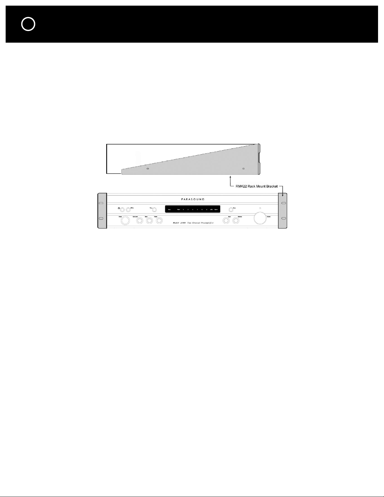
Rack Mounting Your Parasound Model 2100
With its four feet removed, the Model 2100’s front panel height occupies two rack spaces
(3-1/2” or 88.2 mm; a single standard rack space occupies 1-3/4” vertical space.) For mounting in
a standard 19” equipment rack, you must use the Parasound RMK22 rack mount kit (purchased
separately). The RMK22 includes four bolts and eight plastic washers with raised “shoulders.”
Slide one washer onto each mounting bolt with its raised shoulder pointing toward the panel hole.
Carefully insert the bolt through the hole and slide the other washer on the bolt with its raised
shoulder facing the rear side of the panel. The washers will sandwich the Model 2100 panel and
the four mounting bolts to prevent metal-to-metal contact between the Model 2100 chassis, the
equipment rack, and the other components mounted in the rack.
Note: Tighten each bolt just enough to keep the unit secure in the rack to avoid deforming the
shoulder washers. Eliminating metal-to-metal contact reduces the likelihood of creating a ground
loop that might introduce hum into your system.
Page 7
CONNECTING YOUR MODEL 2100
Making Connections
Always disconnect the AC cords to your Model 2100 and power amplifier(s) before making or
changing any input, output or trigger wire connections. Inserting or removing an input or output
cable while the Model 2100 or power amplifiers are turned on can result in a blast of sound
that can damage your loudspeakers. Make sure there is no strain or tension on any cables that
could cause them to pull loose. The Model 2100 has many different types of audio and control
connections, some of which you may not be familiar with. Please read this section thoroughly
before making any connections.
7
AUDIO INPUT CONNECTIONS
The Model 2100 is equipped with a total of 8 audio inputs:
•
6 pairs of line level input jacks; input 1 can be switched to MM or MC phono.
•
An MP3 input jack on the front panel for connecting a portable MP3 player.
•
Bypass Input jacks to connect a home theater surround sound receiver or controller.
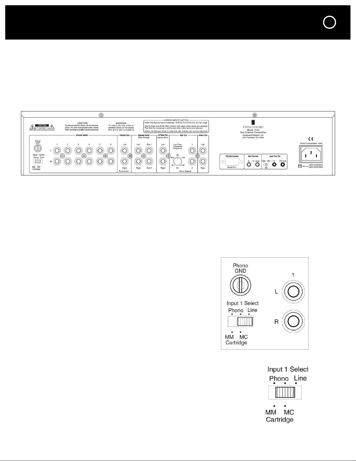
RCA line level Input Jacks
Source inputs 1–6 have the same input sensitivity and input
impedance and they are compatible with any typical analog
line level source. When using input 1 for a standard line level
device (CD, Tape, DVD, tuner, etc.) set the adjacent Input 1
Select switch to Line.
Phono Input (Input 1)
The Model 2100 is equipped with a high quality phono preamplifier. If you
wish to connect a turntable, set the Input 1 Select switch to MM (moving
magnet) or MC (moving coil), depending on your cartridge. Select MM if
you are not sure which type of phono cartridge you have because
MM cartridges are more common.
Note: If your turntable won’t reach adequate volume, or if it plays too loud,
you have selected the incorrect cartridge type. Don’t forget to connect the
ground wire from your turntable to the Phono Gnd (ground) terminal on
the Model 2100.
Page 8
8
CONNECTING YOUR MODEL 2100 continued
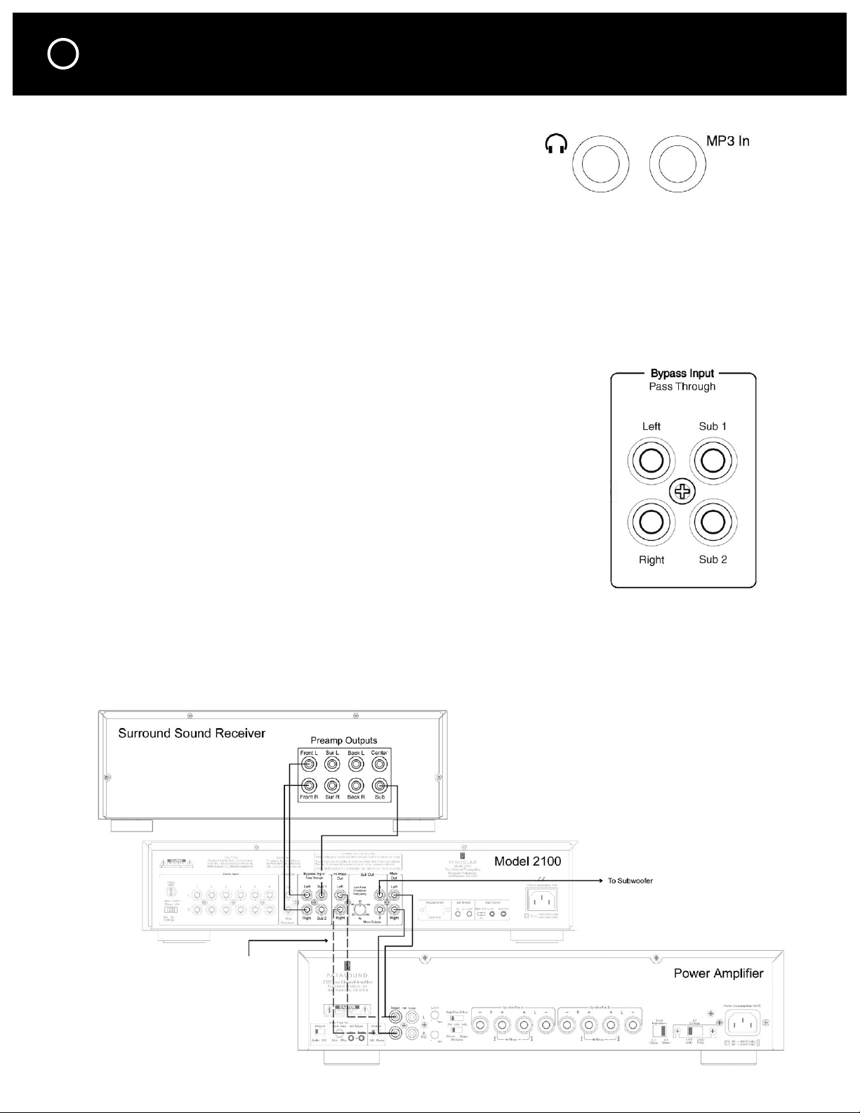
Front Panel MP3 Input
For your convenience there is an input for a portable MP3 player
on the front panel. Connect the included cable with the 3.5mm
stereo plugs between the MP3 player’s headphone jack and the
Model 2100’s MP3 input jack. The MP3 input boosts the input
signal by 12dB so that its volume level will be similar to your other source components.
For the best results, set your MP3 player’s volume to around 75% of maximum.
Note: If you connect a component other than an MP3 player to the MP3 Input jack, the volume
level will probably be too high.
Bypass Input (Pass Through)—stereo system only
If your Model 2100 is not being combined into a surround system, you can skip this section
and go directly to AUDIO OUTPUT CONNECTIONS.
Bypass Input (Pass Through)—in a surround sound system
The Bypass Input is used to incorporate the Model 2100 into a surround
system which includes a surround sound receiver. It controls your stereo
sources independent from your surround receiver to optimize the sound
quality. In order to use the Bypass Input your surround sound receiver
must have line level preamp output jacks.
When the Bypass Input is selected the incoming signals at the Bypass
Input Left & Right jacks are connected directly to the Main Out Left &
Right jacks and the Hi Pass Out jacks.
When the Bypass Input is selected the incoming signals at the Bypass Input
Sub 1 & Sub 2 jacks are connected directly to the Sub Out 1 & 2 jacks.
Connecting the Bypass Input
Connect your surround sound receiver’s Left, Right & Sub channel preamp output jacks to the
Model 2100’s Left, Right & Sub Bypass Input jacks. With a single subwoofer you can use either
the Sub 1 or Sub 2 Bypass Input jack.
Note: Two Bypass Sub Input jacks are included in case you have two subwoofers and your
surround receiver includes two Sub out jacks.
Note: For small speakers with a subwoofer,
connect the Hi Pass Out Jacks
instead of the Main Out jacks.
Page 9

CONNECTING YOUR MODEL 2100 continued
Selecting the Bypass Input
The Bypass Input can be selected by two different methods.
Manual: When the Model 2100 is turned on you can select the Bypass Input with the remote
control or front panel Input selector knob.
Auto: The Bypass Input is automatically selected whenever the Model 2100 is turned off. This
makes it easy to use your surround sound equipment even without turning the Model 2100 on.
Note: When the Bypass Input is selected the Model 2100 volume control, tone controls, internal
crossovers and mute circuits are disabled. Volume and other functions are entirely controlled by
your surround sound receiver.
Note: Important details about the Bypass Input
The Model 2100’s Bypass function is a direct connection from its Bypass Input jacks to its
Hi Pass, Main and Sub output jacks. None of the Model 2100’s internal crossovers are active:
The Hi Pass Out jacks are full range; the 80Hz crossover is inactive.
The Sub Out jacks are full range; the Low Pass crossover is inactive.
This is done intentionally so the bass management built into your surround sound receiver
functions normally when you are listening to surround sound. Please see the owner’s
manual for your surround sound system to setup the proper speaker levels, distance and bass
management. If you have already calibrated your surround sound system, there is no need to
recalibrate your system after adding the Model 2100. Don’t forget that the volume control on
the Model 2100 does not work when the Bypass Input is selected. Use the volume control on
your surround sound equipment.
9
NOTE: DO NOT CONNECT A SOURCE COMPONENT SUCH AS A CD, DVD,
TAPE DECK OR TUNER DIRECTLY TO THE MODEL 2100’s BYPASS INPUT.
SINCE THERE IS NO VOLUME CONTROL WITH THIS INPUT THE SOUND
LEVEL COULD BE EXTREMELY HIGH AND COULD DAMAGE YOUR SPEAKERS—
EVEN WHEN THE MODEL 2100 IS TURNED OFF.
How to improve stereo sound in a surround sound system
Your 2-channel analog sources will give you clearer sound if you disconnect them from your
surround sound receiver’s analog input jacks and reconnect them to any pair of the Model
2100’s Input 1-6 jacks. You can now select these analog sources and control their volume,
balance and tone with the Model 2100.
For better stereo reproduction with your DVD player, connect its L & R analog output jacks to
one pair of the Model 2100’s Input 1-6 jacks. You’ll now select the DVD player’s stereo analog
output and control its volume, balance and tone with the Model 2100.
This recommended analog connection between your DVD player and the Model 2100 is in
addition to any existing digital connection between your DVD player’s digital output and your
surround sound receiver’s digital input. Your surround sound receiver will continue to select
the DVD player when you want to hear surround sound, exactly the same as it did before you
brought the Model 2100 into your home theater.
Page 10

10
CONNECTING YOUR MODEL 2100 continued
AUDIO OUTPUT CONNECTIONS
There are 4 pairs of output jacks labeled Main Out, Sub Out, Hi Pass Out and
Record Out. All of the outputs are active simultaneously. Read through this
section to determine which you should use for your setup.
Main Output Jacks
The Main Output Jacks are the primary outputs that connect to the inputs on
your power amplifier(s). They are full range outputs with no filters or crossovers.
Use these jacks if your speakers are full range and you aren’t using a subwoofer.
Sub Out Jacks—no subwoofer in your system
If you don’t use a subwoofer in your system, you can skip this section.
Sub Out Jacks—when Inputs 1–6 or the MP3 Input are selected
•
A mono Sub output is created by the Model 2100.
•
Sub 1 & 2 Out jacks carry the same mono signal.
•
The crossover point of the Sub Out jacks is determined by the setting
of the Low Pass Crossover Frequency knob.
For an independent stereo system, adjust to taste. When the
Model 2100 is connected to a surround receiver, adjust the
crossover frequency so it matches the bass management setting
in your surround receiver’s setup menu.
Note: 80Hz is the best place to start if you are not sure how to set
the crossover frequency.
Note: If your subwoofer has a built-in non-defeatable crossover,
set it to its highest frequency to avoid double filtering.
Sub Out Jacks—when the Bypass Input is selected
•
Sub Out 1 & 2 jacks carry independent L & R signals from the Bypass L & R Input jacks.
•
There is no crossover.
Hi Pass Output Jacks—no subwoofer in your system
If your speakers are full range, you can skip this section.
Hi Pass Output Jacks—“small” speakers + sub
The Hi Pass Output jacks are for use when your speakers are small (woofer
drivers 6” or smaller) and you are using a subwoofer. The Hi Pass outputs do not
carry bass below 80Hz. The crossover point is fixed.
The Hi Pass Outputs are full range when the Bypass Input is selected. In this
case the high pass filter is not active so you will use the bass management in
your surround sound receiver’s setup menu.
Page 11
CONNECTING YOUR MODEL 2100 continued
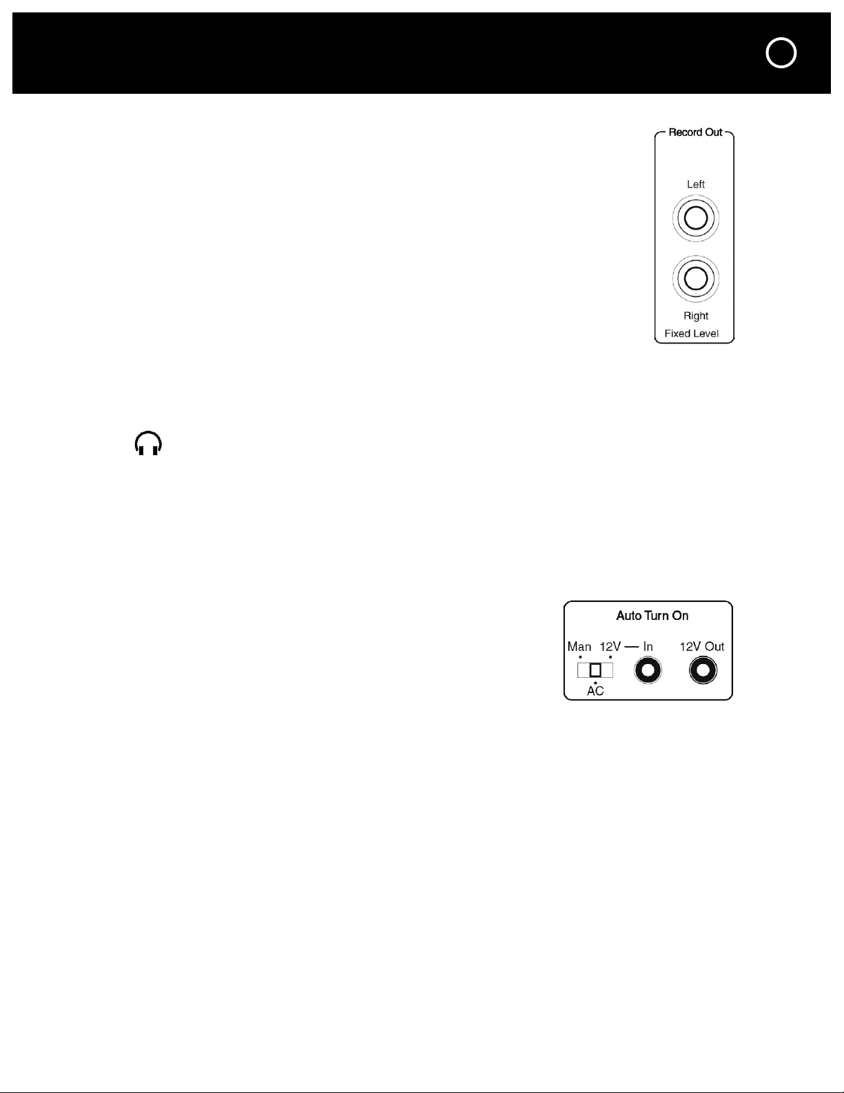
Record Out Jacks
The Record Out jacks connect to your analog audio recorder’s record/input jacks.
When you select an Input 1–6 or MP3, the signal from the corresponding source
component is available at the Record Out jacks whenever the Model 2100 is
turned on. It is a fixed level signal that is unaffected by volume, balance and tone
settings or audio mute.
When you select the Bypass Input, there is no signal available at the
Note:
Record Out jacks. The Model 2100 does not enable monitoring the quality of a
recording as you are making it.
Connecting a Signal Processor to Your Model 2100
You can connect a signal processor such as an electronic crossover or equalizer
between the Model 2100 and your power amplifier(s). The signal processor’s
input should be rated to accept the Model 2100’s maximum output voltage
without overloading. You can also adjust the gain controls of your power amplifier(s) and signal
processor for the lowest noise level.
OTHER CONNECTIONS
11
The headphone jack accepts a 1/8” (3.5 mm) mini plug. The Main audio out is muted when
the headphone plug inserts into this jack, but the output to the Fixed–Rec jacks remains live.
Note: Please lower the volume level on the Model 2100 before unplugging your headphones
to avoid an unexpected loud blast of sound that could damage your speakers.
TRIGGERING OTHER COMPONENTS ON/OFF
12V Trigger Out
There is one 12 volt trigger output and one input. The output can
be used to turn on power amplifiers and other equipment that are
equipped with automatic turn-on inputs. Connect the Model 2100’s
12V output jack to the triggered component’s trigger input jack
using the provided trigger wire with the 2.5 mm sub-mini plugs.
Note: Most Parasound Power Amplifiers are equipped with a 2.5
mm “sub-mini” 12V trigger input jack. The trigger voltage source is DC and the trigger plug tip is
+ (positive) and its sleeve – (negative). The trigger output has a maximum current capacity of 150
mA. Parasound power amplifier trigger inputs require a mere 15 mA.
AUTO TURN ON
12V Trigger In
The 12V trigger input can be used to turn the Model 2100 power on automatically. In this case the
Model 2100 would be turned on and off by another device such as a home automation system.
Note: When the Auto Turn On switch is set to 12V or AC the front panel Power button and
remote control On and Off buttons are disabled.
AC Power Trigger
The Model 2100 will turn on automatically when its AC power source is switched on. To use
AC auto turn on first set the Auto Turn On switch to its AC position.
Note: When the Auto Turn On switch is set to 12V or AC the front panel Power button and
remote control On and Off buttons are disabled.
Page 12

12
CONNECTING YOUR MODEL 2100 continued
External Remote Input
Your Model 2100 is compatible with most popular infrared repeater systems
for remote control operation from another room or when the Model 2100
is installed in a cabinet where its remote handset signals cannot reach its
front panel remote control sensor. The External Remote Input connector is
a standard 1/8” (3.5 mm) “mini” jack. The center conductor (plug tip) is for
+ and the outer conductor (plug sleeve) is for – . Your Authorized Parasound
dealer or custom installer can recommend a compatible IR repeater system.
RS-232 Serial Port
This 9-pin female DB9 connector is a full-duplex serial port. This permits the Model 2100 to
communicate in two directions with home automation and control systems such as Crestron,
AMX, Control4, Niles and Elan. When the Model 2100 is connected to such a device, it can be
controlled and its status monitored from keypads or touch-screen
panels throughout your house. The capabilities of such connections,
and the programming and interfacing needed will depend on the
automation system you select; consult your Parasound dealer or
custom installer for more information regarding interfacing an external
control system to your Model 2100.
The complete RS-232 protocol and code table can be found
on page 17 of this manual and at: www.parasound.com.
Note: The Model 2100 volume setting cannot be monitored
from the RS-232 port because it is an analog control.
AC Power
The IEC standard AC cord supplied with your Model 2100 is an
audiophile-grade component. Please connect it directly to an AC
wall outlet that is always “live.” If possible, plug your Model 2100
into the same AC outlet that your accompanying audio components
(particularly your source components and power amplifiers) are
plugged into. If different AC outlets are used the ground potential
may be higher or lower between the outlets, resulting in audible hum.
Before turning the Model 2100 on, recheck all your connections and turn down the volume
control to avoid any unpleasant “blasts” that could damage your speakers.
Page 13

OPERATING YOUR MODEL 2100
FRONT PANEL CONTROLS
Power Button
A soft red glow surrounds the Power button when the Model 2100 is turned off. Push the
Power button once to turn on and the red glow will extinguish. When the Model 2100 is turned
on, the Input indicator and the selected input will illuminate green. The Mute LED will light up
during a 4–5 second delay after turn on. After the circuits stabilize the muting will disengage.
Push the Power button again to turn it off.
Note: The front panel Power button and remote control On and Off buttons are disabled when
the rear panel Auto Turn On switch is set to 12V or AC.
Sub Level Knob
The Sub Level control knob adjusts the subwoofer level. The sub level can be adjusted
between –10 and +10 dB, relative to the L and R channels. When the control knob is in the
12 o’clock position the sub level is boosted by 0 dB.
Bass and Treble Knobs
The Bass and Treble knobs adjust tone. Very slight tone adjustments can restore warmth, richness,
clarity and airiness that might be missing on certain recordings or because of room acoustics.
Larger tone adjustments will obscure musical detail, and even risk overloading your speakers.
Tone adjustments are audible only when the Tone indicator in the front panel display is lit.
13
Tone Button
Press the Tone button once to engage the bass and treble tone control circuits. Press a second
time to turn them off.
Tone is on when the Tone indicator in the front panel display is lit. The Tone button lets you
hear the difference between sound without tone adjustments (“flat”) and sound with the tone
adjustments you made.
Note: You’ll hear the clearest sound when Tone is turned off and the audio signal path bypasses
the tone circuits.
Mute Button
Pressing the Mute button once will mute the signal at all of the Out jacks except the Record
Out. The red Mute light will flash on the front panel while mute is engaged. Press the Mute
button a second time to cancel mute.
Input Knob
Rotating the Input selector will cycle through all 8 inputs. The front panel display indicates
which input is selected.
Balance Knob
Adjusting left and right channel balance is helpful to compensate for speaker placement,
room acoustics or if your power amplifier’s gain isn’t identical for both channels.
Volume Knob
Your Model 2100 uses a high quality potentiometer to adjust the master volume level. Adjust
your power amplifier gain controls (if it has them) so that your Model 2100 master volume knob’s
indicator is between 11 o’clock and 1 o’clock for your most typical listening level. This is its
“sweet spot” where the control’s left/right channel tracking is closest and its distortion is lowest.
Note: The Model 2100 has a gain of 12 dB, which is suitable for most brands of power
amplifiers and is an ideal match for all Parasound power amplifiers.
Page 14

14
OPERATING YOUR MODEL 2100 continued
REMOTE CONTROL FUNCTIONS
The Model 2100 remote control has a maximum range of
approximately 20–25 feet (6–7.5 meters). Use only AAA
alkaline batteries in the handset and insert them according to
the + and – polarity markings in the battery compartment.
On and Off Buttons
These have the same function as the Power button on the front
panel. These separate buttons enable programming unambiguous
“hard” off and on commands into a system controller or to create
a macro sequence for a learning-type remote control.
Note: The On and Off buttons are disabled when the rear panel
Auto Turn On switch is set to 12V or AC.
Mute Button
Pressing the Mute button once mutes the signal at all of the
Out jacks except the Record Out. The red Mute light will flash
on the front panel while mute is engaged. Press the Mute button
a second time to cancel mute.
Volume and Buttons
These buttons control the rotation of the front panel motorized
Level control to increase and decrease listening volume levels.
Tone On and Off Buttons
Press the Tone On and Off buttons to engage or disengage the
bass and treble tone control circuits. The remote lets you hear
whether “flat” or adjusted tone sounds better at your favorite
listening position.
Note: The remote control cannot make the Bass and Treble
adjustments; these adjustments must be made with the
Model 2100’s front panel Bass and Treble knobs.
Source Input Buttons
Press the Input button of the source that you wish to hear.
“BURNING-IN” YOUR MODEL 2100
Like many other great high end preamplifiers, your Model 2100 should operate for at least
72 hours with music playing after it is first turned on before it will sound its best. Any
volume level is ok. This gives various internal components and wiring a chance to “form”
their optimum electron pathways so they can pass complex musical information with greater
definition, smoothness and transparency. Although your Model 2100 will sound spectacular
when you first turn it on, you will come to appreciate it even more as your listening hours
accumulate. You’ll discover additional musical details you may not have known were present.
Page 15

FREQUENTLY ASKED QUESTIONS
Before turning the Model 2100 on, recheck all your connections and turn down the volume
control to avoid any unpleasant “blasts” of sound that could damage your speakers.
Why is there no sound from the speakers?
•
Is the AC power live? You should see a faint red glow around the Power button
when the unit is turned off, but plugged into a live AC power source.
•
Check that input and output cables are secure at both ends.
•
Make sure your Model 2100 is switched to the correct input.
What could cause the remote to fail to operate?
•
Weak or dead batteries. Replace; information about battery recycling: www.Earth911.org.
•
Insure that the front panel IR receiver is not obscured or exposed to direct sunlight or to an
LCD or a plasma TV screen.
I can hear a background hum from the speakers
•
Move audio cables and AC cords away from each other (while power is off).
•
Try to route audio cables and AC cords perpendicular to each other (while power is off).
•
Make sure insulating shoulder washers are used if unit is rack mounted.
•
Reverse the direction of the other components’ AC plugs, one-by-one (while power is off).
•
Insure that the power amps and the Model 2100 are plugged into the same AC outlet.
•
The turntable ground wire must be attached to the GND terminal.
15
The Sound is distorted and weak
•
Make sure the gain of the power amp is not set too low.
•
Are you trying to use the Model 2100 with a turntable? Make sure you have set the phono
selector switch to the correct cartridge type.
•
Make sure the stereo power amp’s stereo/mono switch is set to stereo.
MAINTAINING YOUR MODEL 2100
Your Model 2100 requires no periodic maintenance and has no user-serviceable parts inside.
To avoid risk of electric shock do not remove the top cover. To keep it clean use only a soft cloth
moistened with a few drops of clear water or Windex. Never use any solvents or abrasives.
The remote control handset batteries should be removed whenever it will be unused for an
extended period. Remove the battery cover annually to inspect and remove leaking batteries.
Page 16

16
ARE YOU HAVING DIFFICULTY?
Warranty Repair
Call your Parasound dealer first. If the dealer can’t help you with your problem we encourage you
to call Parasound’s Technical Service Department, toll-free at 1-866-770-8324, Monday – Friday,
8am – 4pm Pacific time. We can suggest other diagnostic tests you can easily perform.
If we determine that your Model 2100 should be returned to Parasound or an Authorized
Parasound Warranty Center for inspection and possible servicing, we will provide the location
of a warranty center near you or shipping instructions for the unit’s return to Parasound.
Before You Return Any Unit to Parasound for Service
Before you send your unit to Parasound, you will need to obtain a specific Return Authorization
(RA) number and shipping instructions from Parasound’s Technical Department. The RA number
must be clearly marked on the outer carton. Use the original factory packing materials and arrange
adequate insurance to cover its value. You must include a copy of your purchase receipt, since
this document establishes the validity of this unit’s warranty. Warranty repairs are only performed
by Parasound or Parasound Authorized warranty centers when your purchase receipt is from a
Parasound Authorized Dealer or Parasound Authorized Reseller.
Units Will Be Refused by Parasound Under the Following Conditions
1. Unit was sent without the Parasound-assigned RA number marked on the carton.
2. Unit was sent in an unsuitable shipping carton and is likely to have been damaged in transit.
3. Unit has inadequate packing materials and is likely to have been damaged in transit.
4. Unit was shipped collect for shipping charges. We do not accept collect shipments.
5. Unit was shipped via the US Postal Service.
6. Unit was sent to an address other than the address instructed by our Technical Department.
Note: The Parasound Technical Department shipping address is not the same as Parasound’s
office address. The Parasound office does not accept packages.
Warranty Repair
Read your accompanying Parasound Limited Warranty carefully to understand the applicable rights
and limitations. This section provides instructions for obtaining repairs, both for units covered
under the Parasound Limited Warranty and for units or situations which are outside the Warranty.
Unit is not eligible for repair under the terms of the Parasound warranty if:
1. Unit was not purchased from a Parasound Authorized Dealer.
2. You do not have the original bill of sale or sales receipt from a Parasound Authorized Dealer.
3. You are not the original owner. The Parasound warranty is not transferable.
4. Unit’s serial number was removed, modified, or defaced.
5. Unit shows evidence of abuse and/or misuse.
6. Unit was modified in any way.
7. A prior repair was attempted by an unauthorized repair station.
Page 17

RS-232 PROTOCOL & CODE TABLE
Protocol Specs Pin Connections
Baud Rate: 9600 bps TxD: Pin 2
Data Bit: 8 bits RxD: Pin 3
Stop Bit: 1 bit Gnd: Pin 5
Parity: None
Flow Control: No
Basic RS-232 Control:
ASCII (not decimal) and hexadecimal examples are shown below. The commas in the Hex
example are merely for your ease of reading and are not required in transmission. All strings must
have a space between each number or letter (except two digit numbers). In the Hex examples the
space is already represented with code “20.” The end of each string must have a carriage return
after the last number with no space in-between, this is represented by “<CR>” in the ASCII
examples and “0D” in the Hex examples.
Command String ASCII String Hexadecimal
Power On W 1 1 2<CR> 57,20,31,20,31,20,32,0D
Power Off W 1 1 1<CR> 57,20,31,20,31,20,31,0D
Power Toggle W 1 1 3<CR> 57,20,31,20,31,20,33,0D
Volume Up W 1 9 1<CR> 57,20,31,20,39,20,31,0D
Volume Down W 1 9 2<CR> 57,20,31,20,39,20,32,0D
Mute On W 1 10 2<CR> 57,20,31,20,31,30,20,32,0D
Mute Off W 1 10 1<CR> 57,20,31,20,31,30,20,31,0D
Mute Toggle W 1 10 3<CR> 57,20,31,20,31,30,20,33,0D
Input 1 W 1 2 6<CR> 57,20,31,20,32,20,36,0D
Input 2 W 1 2 7<CR> 57,20,31,20,32,20,37,0D
Input 3 W 1 2 8<CR> 57,20,31,20,32,20,38,0D
Input 4 W 1 2 9<CR> 57,20,31,20,32,20,39,0D
Input 5 W 1 2 10<CR> 57,20,31,20,32,20,31,30,0D
Input 6 W 1 2 11<CR> 57,20,31,20,32,20,31,31,0D
Input MP3 W 1 2 12<CR> 57,20,31,20,32,20,31,32,0D
Input Bypass W 1 2 13<CR> 57,20,31,20,32,20,31,33,0D
Next Input W 1 2 4<CR> 57,20,31,20,32,20,34,0D
Previous Input W 1 2 5<CR> 57,20,31,20,32,20,35,0D
Tone On W 1 3 1<CR> 57,20,31,20, 33,20,31,0D
Tone Off W 1 3 2<CR> 57,20,31,20, 33,20,32,0D
Tone Toggle W 1 3 3<CR> 57,20,31,20, 33,20,33,0D
17
Please Note: ”<CR>” stands for Carriage Return and the Hex Code is “0D”.
A space in Hex is “20”, a space in ASCII is just a blank space (as shown above).
Page 18

18
MODEL 2100 RS-232 PROTOCOL continued
Feedback Information:
Unsolicited feedback is sent anytime that the MODEL 2100 is controlled by IR remote, Front Panel
or by RS232. Even if the MODEL 2100 is turned off it should send full feedback. Full unsolicited
feedback will be automatic and in this format:
*G1 S3 M1 T0<CR>
* = Start of transmission
<CR> = End of transmission
G0 = Power Off, G1 = Power On
S1 = Input 1, S2 = Input 2, S3 = Input 3, S4 = Input 4, S5 = Input 5, S6 = Input 6
S7 = Input MP3, S8 = Input Bypass
M0 = Mute Off, M1 = Mute On
T0 = Tone Off, T1 = Tone On
Volume Feedback *V0<CR> and *V1<CR>
Because the volume control is a motor driven type there is no exact feedback of the current
volume setting. When the volume is turned up or down from the remote or RS232, feedback will
be transmitted confirming the volume was increased or decreased. This will be represented by a
“*V0<CR>” for volume decrease and “*V1<CR>” for volume increase.
You can request the status of the MODEL 2100 by issuing the following commands:
Request String ASCII String Hexadecimal Response From 2100
Current Input
Power Status
Mute Status
Tone Status
R 1 2<CR 52,20,31,20,32,0D *S1<CR>
*S2<CR>
*S4<CR>
*S5<CR>
*S6<CR>
*S7<CR>
*S8<CR>
R 1 1<CR> 52,20,31,20,31,0D *G0<CR>
*G1<CR>
R 1 10<CR> 52,20,31,20,31,30,0D *M0<CR>
*M1<CR>
R 1 4<CR> 52,20,31,20,34,0D *T0<CR>
*T1<CR>
Full Status
R 1 13<CR> 52,20,31,20,31,33,0D *G1 S2 M0 T0<CR>
Page 19

MODEL 2100 SPECIFICATIONS AND SETUP NOTES
19
Audio Specifications
Frequency Response
10 Hz – 100 kHz, +0/–3 dB
THD Distortion
< 0.008% at 20 Hz
S/N Ratio
> 105 dB, input shorted, IHF A-weighted
> 95 dB, input shorted, unweighted
Crosstalk
> 75 dB at 20 kHz
Input Impedance
30k ohms
Output Impedance
< 60 ohms
Input Sensitivity
250 mV for 1 V output
Total Gain: 12 db
Maximum Output: 6.5 V
AC Power Requirement
110-250 V, 50 - 60 Hz
Voltage is automatically selected
5 watts standby; 10 watts when turned on
General Information
Dimensions
Width: 17.25” (437 mm)
Depth: 14.5” (369 mm)
Height, with feet: 4.25” (108 mm)
Height, without feet: 3.5” (89 mm)
Weight: Net: 13 lbs. (5.9 kg)
Shipping: 20 lbs. (9.1 kg)
Rack Mount Accessory
RMK22 (May be purchased separately)
Notes:
Note: Specifications and features subject to change or improvement without notice.
© 2007 Parasound Products, Inc. Crestron, AMX, Control4, Niles and Elan are registered trademarks. Rev. 0.9
Page 20

 Loading...