

Paramount Furniture FS-52 User Manual
FS-52
I
NNER / OUTER THIGH
ASSEMBLY MANUAL
AM-FS52

A MESSAGE TO OUR CUSTOMERS
Thank you for purchasing the Paramount FS-52 Inner / Outer Thigh machine. Because of the many
unique features included in this product, this manual was created to provide you with information on
how to properly assemble and maintain your equipment. Proper maintenance will ensure that your
new equipment will last for years.
For your convenience, product questions can be answered by an Authorized Paramount Dealer or by
contacting a Paramount Customer Service Representative at:
1-800-721-2121 or 1-323-721-2121 or nasales@paramountfitness.com
Office hours are Monday-Friday, 7:30 am - 4:30 pm PST
Paramount Fitness Corporation
6450 East Bandini Blvd.
Los Angeles, CA 90040
IMPORTANT
!
REVIEW THE GENERAL MAINTENANCE MANUAL FOR IMPORTANT SAFETY AND
MAINTENANCE TIPS. THE MANUAL HAS BEEN INCLUDED WITH YOUR MACHINE ORDER
AND CAN ALSO BE DOWNLOADED FROM OUR WEBSITE AT:
http://www.paramountfitness.com
PLEASE RETAIN THIS MANUAL FOR FUTURE REFERENCE.
2

TABLE OF CONTENTS
SAFETY...................................................................................................................... 4
G
ENERAL CARE AND MAINTENANCE........................................................................... 5
IMENSIONS AND WEIGHT........................................................................................... 6
D
REPARATION............................................................................................................. 7
P
FS-52 C
FS-52 C
NSTALLATION & ASSEMBLY
I
ARTON 1 CONTENTS........................................................................................ 8
ARTON 2 CONTENTS........................................................................................ 9
STEP 1: ASSEMBLE THE FRAME COMPONENTS................................................. 10
TEP 2: ASSEMBLE THE ADJUSTMENT PLATE................................................... 12
S
S
TEP 3: ASSEMBLE THE LEFT ARM................................................................... 13
TEP 4: ASSEMBLE THE PADS........................................................................... 14
S
TEP 5: ASSEMBLE THE CONNECTING PLATE................................................... 15
S
S
TEP 6: INSTALL THE WEIGHT STACK.............................................................. 16
TEP 7A: INSTALL THE CABLES....................................................................... 17
S
TEP 7B: INSTALL THE CABLES........................................................................ 18
S
S
TEP 8: INSTALL THE CAM COVER................................................................... 19
TEP 9: INSTALL THE FRONT SHROUD.............................................................. 20
S
TEP 10: INSTALL THE REAR SHROUD.............................................................. 21
S
S
TEP 11: APPLY THE WEIGHT STACK LABEL.................................................... 22
ACHINE LABELS........................................................................................................ 23
M
ERVICE..................................................................................................................... 24
S
P
ARAMOUNT LIMITED WARRANTY.............................................................................. 26
3

SAFETY
1. Review and understand all of the warning labels affixed to this machine and on the facility safety
sign. Replace any warning label at first sign of wear. Labels and the Facility Safety Sign may be
obtained from Paramount free of charge.
2. Be certain that the machine operation is understood before it is used. Refer to the instruction label
provided with the machine.
3. Keep children away from this equipment. Supervise use by teenagers.
4. DO NOT high-pin or double-pin the weight stack. DO NOT allow the machine to be used if the top
plate or weight stack is pinned in a raised position. Use an assistant and carefully return the
machine to the proper position with the cap plate resting on the top weight. Inspect the cable to
ensure that it is seated in all of the pulleys.
5. Use ONLY Paramount weight selector pins. Other manufacturer’s pins may work free of the weight
stack causing possible injury. Be certain the pin is completely inserted prior to use.
6. Cables: Inspect the entire cable weekly and the end fittings daily. Pay close attention to the area
going over pulleys and to the end connections. Replace all cables at first signs of wear or on an
annual basis. Use only Paramount supplied replacement cables.
7. Nuts, Bolts, and Fasteners: Check tightness weekly. If any hardware has become loose, retighten
and/or use Loctite
8. Frames and Lifting Arms: Inspect weekly for integrity and function. Replace any component at first
signs of wear.
9. Adjustment Pins: check the function of the position selector pins on the adjustable arms. Make
sure that the selector pin inserts completely into each position without binding.
10. DO NOT attempt to free any jammed assemblies by yourself as this may cause injury.
11. DO NOT use adder weights or adder weight systems on this machine.
12. Instruct Users NOT to make arm position adjustments during exercise or when pulling on the
cable end. Always support the arms when making position adjustments.
13. Instruct Users to return the handgrips and bars to their rest position before releasing. Sudden
release of the handgrips and bars may cause serious injury to users or bystanders.
14. Instruct users NOT to attach two cables to single bars or handles. Use one handle or exercise bar
for each weight stack at a time.
15. Instruct Users not to wear loose or dangling clothes or have headphone wire hanging when using
this equipment.
16. It is recommended that users receive a thorough medical exam before commencing an exercise
program. All medical issues should be reviewed to ensure that weight training will not aggravate
pre-existing medical conditions.
17. Check the function of your machine regularly by verifying the following:
• Cables and end fittings are intact.
™
Threadlocker 242.
• All adjustments are possible and carried out with ease.
• The proper selector pin is in the weight stack.
• The exercise is performed smoothly, free of noise and/or binding.
18. Follow the installation guidelines provided with the products.
19. Retain these instructions for future reference.
20. If you have any questions, do not hesitate to contact your Paramount dealer or Paramount
Fitness Corp. at (800)721-2121 or (323) 721-2121 or nasales@paramountfitness.com.
21. Refer to Maintenance Schedule label on the machine and this manual for when to perform
maintenance.
4

GENERAL CARE AND MAINTENANCE
1. Cable Ends: Inspect end fittings daily for wear. Replace cables at the first sign of wear or
on an annual basis. If the cable tension has been adjusted, be certain that the cable nut
is tight.
2. Nuts, Bolts, and Fasteners: Check tightness weekly. If any hardware has become loose,
retighten and/or use Loctite
3. Frames: Wipe all machines down with a damp cloth and dry completely each day. This
includes painted parts, chrome parts and upholstered pads.
4. Painted and chrome plated parts: Use Simple Green or similar cleaner for light dirt and
grime. Use Turtle Wax Polishing Compound or a good car polish to remove heavier dirt
and grease as well as for polishing. DO NOT use solvents, lacquer thinner, acetone or
finger nail polish remover. For scuffs and marks that are not removed by the above
methods use a soft scrub cleanser. Make sure all parts are dry upon completion.
5. Weight stack enclosures (shrouds): Wipe down with a damp cloth as needed.
6. Exercise instruction labels: Clean with soap and water as needed.
7. Guide rods: Wipe all dirt and dust from the guide rods before applying a light application
of Tri-Flow
the guide rods with the rag. DO NOT use oil lubricants such as WD-40. Caution: Tri-Flow
will stain carpet and clothing.
TM
or other teflon spray lubricant. Spray the Tri-FlowTM on a rag and then wipe
TM
brand Threadlocker 242.
TM
8. Bronze bushings: Check monthly for signs of wear and replace as needed. Lubricate
monthly with Tri-Flow
9. Please refer to the General Maintenance Manual (part number: AM-GMM) for other
important safety and maintenance information.
10. Hardware and components are indicated with a balloon. Refer to the hardware tables
that accompany each step for corresponding size and type.
11. Be sure all hardware is tight before using the machine.
!
!
DO NOT install any fitness equipment near a pool, hot tub or other damp locations. Corrosion
caused by installation in these locations can lead to premature failure of components.
After you have unpacked and inventoried all of the components, read through the
remainder of the assembly instructions to familiarize yourself with the assembly
TM
.
procedure!
Each step will require the components shown in the table associated with the step.
Read the instructions for each step before assembling.
5
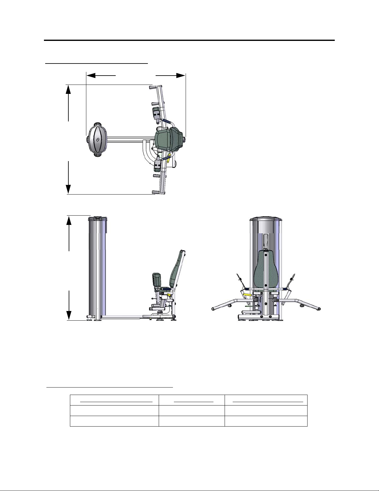
DIMENSIONS AND WEIGHT
“IN USE” MACHINE DIMENSIONS
60.5” (154 cm)
67.0” (170 cm)
64.5” (164 cm)
Maximum user weight: 300 lbs. (136 KG)
MACHINE WEIGHT AND FLOOR LOADING
WEIGHT STACK CONFIGURATION MACHINE WEIGHT APPROXIMATE FLOOR LOADING
170 lbs. 455 LBS [206 KG] 66 LBS/FT2 [322 KG/M2]
250 lbs. 535 LBS 243 KG] 78 LBS/FT
2
[379 KG/M2]
6
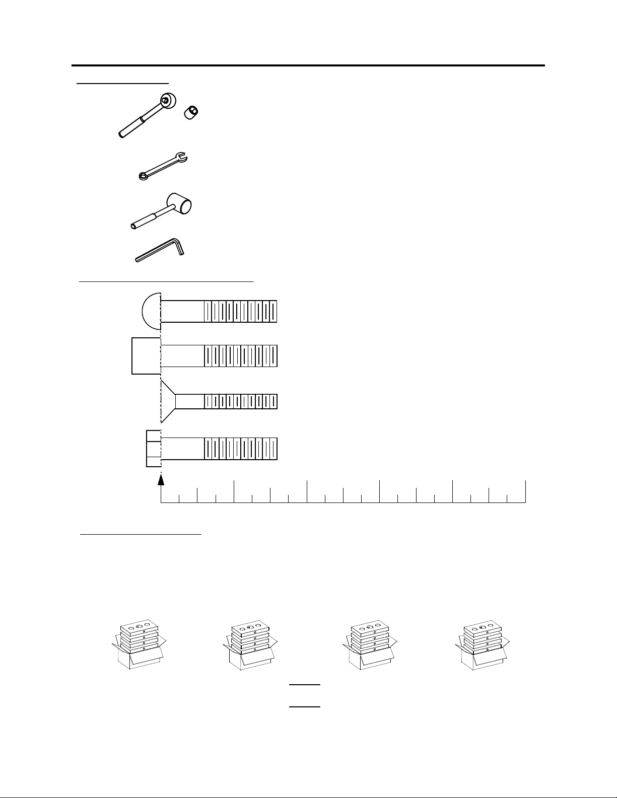
REQUIRED TOOLS:
PREPARATION
Ratchet Wrench and Sockets:
9/16”
Wrenches: 9/16”, 3/4”.
(or an adjustable crescent wrench).
Rubber Mallet and Steel Hammer
Hardware Measurement Guide:
12345
MEASURE BOLT
FROM HERE
Weight Plate Cartons:
Weight plates are packaged (4) per box. You should have (4) boxes of weights. This will
give you a total of 16 weight plates.
Allen wrenches:
BHCS - BUTTON HEAD CAP SCREW
SHCS - SOCKET HEAD CAP SCREW
FHCS - FLAT HEAD CAP SCREW
HHCS - HEX HEAD CAP SCREW
(included with the machine)
The weight plates are available in two different sizes, 10 lbs. and 15 lbs. The 10 lbs. plates
are used on the 170 lbs weight stack, the 15 lbs. plates are used on the 250 lbs. weight
stack. Make sure you know which size weight stack is to be installed on this machine.
10 LB. Weight Plate Box
Part Number: B1602
Comprised of
(4) x 10 lb. Weight Plates
OR
7
15 LB. Weight Plate Box
Part Number: B1603
Comprised of
(4) x 15lb. Weight Plates
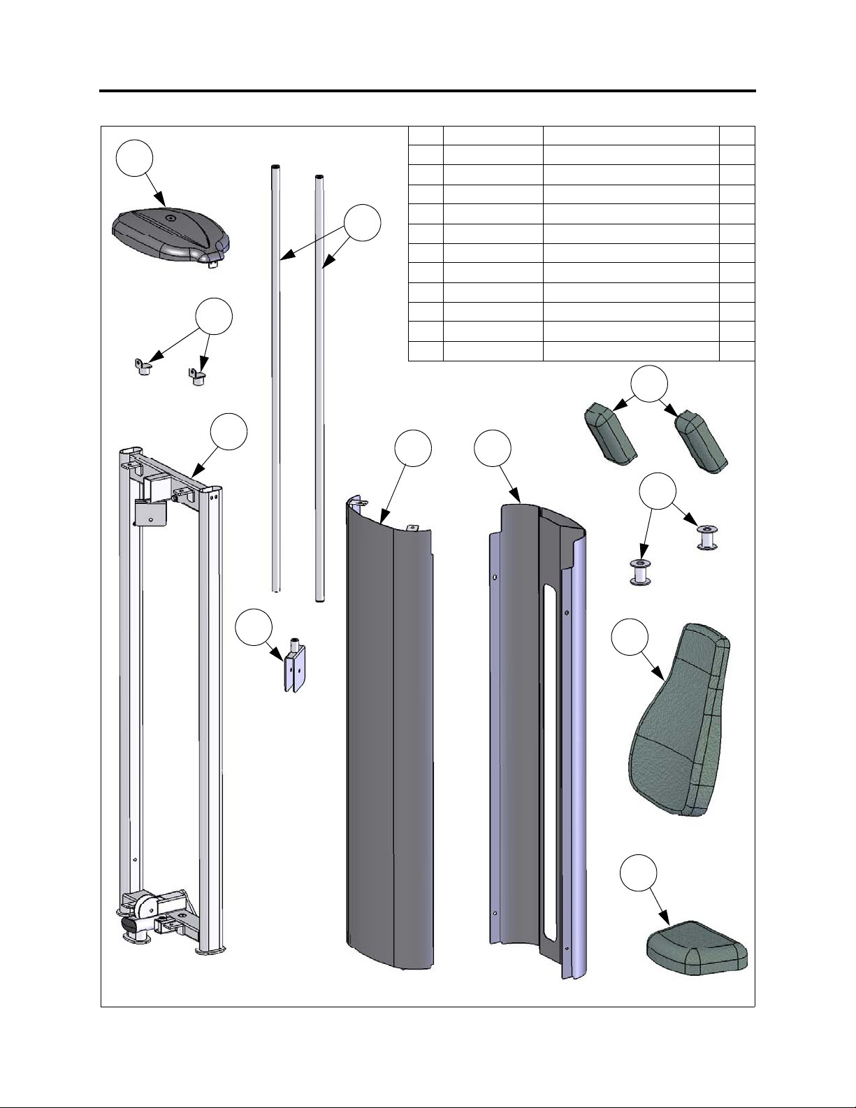
FS-52 CARTON 1 CONTENTS
ITEM PART NO.DESCRIPTION QTY.
1
2
6
5
1 FS-CAP-000X TOP UPRIGHT CAP 1
2 FS-GRD-200X GUIDE ROD 2
3 FS-SHD-250X REAR SHROUD 1
4 FS52-SHD-200X FRONT SHROUD 1
5 FS52-UPR-000X UPRIGHT FRAME 1
6 FS-BKT-000 GUIDE ROD BRACKET 2
7 FS-WSB-000 WEIGHT STACK BASE 2
8 FS52-PAD-100X SEAT PAD 1
9 FS-PAD-000X BACK PAD 1
10 FS-FLT-100X FLOATING PULLEY HOUSING 1
11 FS52-PAD-200X THIGH PAD 2
3 4
11
10
7
9
8
8
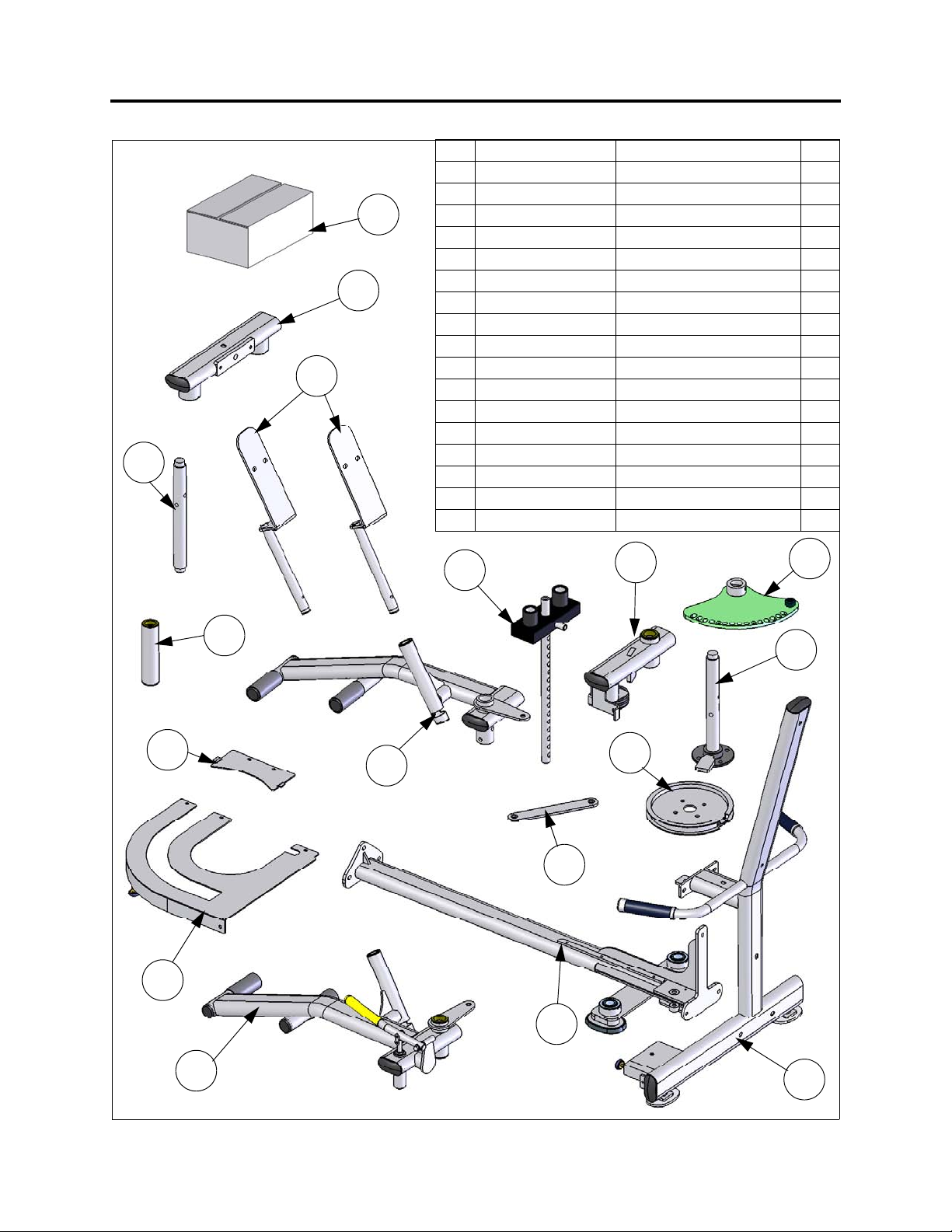
FS-52 CARTON 2 CONTENTS
ITEM PART NO.DESCRIPTION QTY.
1 FS52-MFR-000X MAIN FRAME 1
2 FS52-MFR-100X MAIN FRAME REAR 1
13
5
6
7
3 FS52-ARM-000X LEFT ARM 1
4 FS52-ARM-100X RIGHT ARM 1
5 FS52-MFR-200X ARM RETAINING ASSEMBLY 1
6 FS52-MFR-300X THIGH PAD PLATES 2
7 FS52-AXL-000X AXLE, RIGHT ARM 1
8 FS52-MFR-400X SLEEVE, AXLE SPACER 1
9 FS52-PLT-400X ARM CONNECT PLATE 1
10 FS52-CVR-100X COVER, CAM 1
11 FS52-CVR-200X SMALL COVER, CAM 1
12 FS52-AXL-100X AXLE, LEFT ARM 1
13 FS52-HWR-000X FS-52 HARDWARE BOX 1
14 FS52-ADJ-100X ADJUSTMENT PLATE 1
15 FS52-ARM-200X PULLEY ARM 1
16 FS52-CAM-000X CAM, CABLE 1
17 FS-SBR-000X SELECTOR BAR 1
11
10
17
15
14
8
12
16
4
9
2
3
9
1
 Loading...