


P
PP
PE
EE
ERRRRFFFFOOOORRRRM
MM
MAAAANNNNCCCCE
EE
E XL
XL XL
XL
IIIIN
NN
NSSSSTTTTAAAALLLLLLLLAAAATTTTIIIIOOOON
NN
N M
M M
MA
AA
ANNNNUUUUAAAALLLL
I NNOVATIVE STRENGTH SYSTEMS

2
Thank you for selecting the Paramount XL-Performance Series. Because of the many unique
features included in this product line, this manual was created to prov ide y ou with inf ormation on
how to properly install and maintain your equipment. Proper maintenance will ensure that your
new equipment will last for years.
For your con v eni ence, pr oduc t qu es tion s can be an sw ered b y an A uthor ized Paramount Deale r or
by contacting a Paramount Customer Service Representative at 1-800-721-2121.
Paramount Fitness Corporation
6450 East Bandini Blvd.
Los Angeles, CA 90040
IMPORTANT
IMPORTANTIMPORTANT
IMPORTANT
REVIEW THE GENERAL MAINTENANCE MANUAL FOR IMPORTANT SAFETY AND
REVIEW THE GENERAL MAINTENANCE MANUAL FOR IMPORTANT SAFETY AND REVIEW THE GENERAL MAINTENANCE MANUAL FOR IMPORTANT SAFETY AND
REVIEW THE GENERAL MAINTENANCE MANUAL FOR IMPORTANT SAFETY AND
MAINTENANCE TIPS. THE MANUAL HAS BEEN INCLUDED WITH YOUR MACHINE ORDER
MAINTENANCE TIPS. THE MANUAL HAS BEEN INCLUDED WITH YOUR MACHINE ORDER MAINTENANCE TIPS. THE MANUAL HAS BEEN INCLUDED WITH YOUR MACHINE ORDER
MAINTENANCE TIPS. THE MANUAL HAS BEEN INCLUDED WITH YOUR MACHINE ORDER
AND CAN ALSO BE DOWNLOADED FROM OUR WEBSITE AT:
AND CAN ALSO BE DOWNLOADED FROM OUR WEBSITE AT: AND CAN ALSO BE DOWNLOADED FROM OUR WEBSITE AT:
AND CAN ALSO BE DOWNLOADED FROM OUR WEBSITE AT:
http://www.paramountfitness.com
http://www.paramountfitness.comhttp://www.paramountfitness.com
http://www.paramountfitness.com
PLEASE RETAIN THIS MANUAL FOR FUTURE REFERENCE.
A MESSAGE TO OUR CUSTOMERS
!

3
SAFETY............................................................................................................. 4
G
ENERAL CARE AND MAINTENANCE..................................................................... 5
L
AYOUT AND SPACING - MACHINE DIMENSIONS & WEIGHTS.................................... 6
I
NSTALLATION AND ASSEMBLY
REQUIRED TOOLS..................................................................................... 8
U
NPACK THE HARDWARE BAG.................................................................. 8
F
OOT INSTALLATION................................................................................. 9
W
EIGHT STACK INSTALLATION................................................................... 9
W
EIGHT STACK LABEL INSTALLATION......................................................... 13
OPTIONAL F
RONT PANEL KIT.................................................................. 14
OPTIONAL F
OREIGN LANGUAGE LABELS................................................... 16
A
NCHORING THE MACHINES TO THE FLOOR................................................ 16
F
INAL ASSEMBLY..................................................................................... 16
M
ACHINE MAINTENANCE
REPLACEMENT PARTS: CABLES AND UPHOLSTERED PADS........................... 17
C
ABLES.................................................................................................. 17
XL0300 L
EG PRESS ROLLER ADJUSTMENT............................................... 18
W
ARNING LABELS.............................................................................................. 19
S
ERVICE........................................................................................................... 21
P
ARAMOUNT LIMITED WARRANTY........................................................................ 23
TABLE OF CONTENTS

4
1. Review and understand
Review and understandReview and understand
Review and understand all of the warning labels affixed to the machines and the facility safety
sign. Replace any warning label at first sign of wear. Labels and the Facility Safety Sign may be
obtained from Paramount free of charge.
2. Be certain that machine operation is understood
Be certain that machine operation is understoodBe certain that machine operation is understood
Be certain that machine operation is underst o od bef ore machi ne is use d. R efe r t o the in stru ctio n
label provided with the machine.
3. Keep children away
Keep children awayKeep children away
Keep children away from this equipment. Supervise use by teenagers.
4. DO NOT
DO NOTDO NOT
DO NOT high-pin or double-pin the weight stack. DO NOT
DO NOTDO NOT
DO NOT allow the machine to be used if the top
plate or weight stack is pinned in a raised position. Use an assistant and carefully return the
machine to the proper position with the cap plate resting on the top weight. Inspect the cable to
ensure that it is seated in all of the pulleys.
5. Use ONLY
Use ONLY Use ONLY
Use ONLY Paramount weight selector pins
weight selector pins weight selector pins
weight selector pins. Other manufacturer’s pins may work free of the weight
stack causing possib le injury. Be certain the pin is c o mpletely inser ted p rior to use.
Be certa in the pin is completely inserted p rior to use. Be certa in the pin is completely inserted p rior to use.
Be certa in the pin is completely inserted p rior to use.
6. Cables
CablesCables
Cables: Inspect the entire cabl e w ee kly and the end fittings daily . P ay close attention to the area
going over pulleys and to the en d connections. When adjusting cables at threaded inserts make
sure all connections are tight. Adjust tension on cables as needed. Replace al l cabl es at fi rst signs
of wear or on an annual basis. Use only Paramount supplied replacement cables. Ensure that the
dimension from under the bolt head to the top surface of the selector bar is no greater than 1-3/8
inches. Ensure that the cable tension bolt & nut are tight.
7 . Nuts, Bolts, and Fasteners:
Nuts, Bolts, and Fast eners: Nuts, Bolts, and Fast eners:
Nuts, Bolts, and Fasteners: Check tightness week ly. If any hardware has become loose, reti ght en
and/or use Loctite
™
Threadlocker 242.
8. Frames and Lifting Arms:
Frames and Lifting Arms:Frames and Lifting Arms:
Frames and Lifting Arms: Inspect weekly for integrity and functi on. Replace any component at f irst
signs of wear.
9. DO NOT
DO NOTDO NOT
DO NOT attempt to free any jammed assemblies by yourself as this may cause injury.
10. Use ONLY
Use ONL Y Use ONLY
Use ONL Y Paramount adder weights or adder weight syst ems
adder weights or adder weight systems adder weights or adder weight systems
adder weights or adder weight systems for incre mental resi stance
adjustment. NEVER
NEVERNEVER
NEVER use dumbbells or other means to do this.
11. The Maximum
MaximumMaximum
Maximum user weight for this equipment is 300 lbs. (136 kg.)
12. Instruct Users
Instruct UsersInstruct Users
Instruct Users not to wear loose or dangling clothes or have headphone wire hanging when using
this equipment.
13. It is recommended
It is recommended It is recommended
It is recommended that users receive a thorough medical exam before commencing an ex er cise
program. All medical issues should be reviewed to ensure that weight training will not aggravate
pre-existing medical conditions.
14. Check regularly
Check regularlyCheck regularly
Check regularly the functionality of your machine by verifying the following:
• Cables and end fittings are intact and tensioned properly.
• All adjustments are possible and carried out with ease.
• The proper selector pin is in the weight stack.
• The exercise is performed smoothly, free of noise and/or binding.
• And the guide rods and linear bearings are properly lubricated.
15. Follow the installation guidelines
Follow the installation guidelinesFollow the installation guidelines
Follow the installation guidelines provided with the produc ts.
16. Retain these instructions
Retain these instructionsRetain these instructions
Retain these instructions for future reference.
17. If you have any questions, do not hesi tate to contac t your P aramount dealer or Paramount Fitness
Corp. at (800)721-2121 or www.paramountfitness.com.
18. Refer to Maintenance Schedule la bel on the machine for when to perform maintenance.
SAFETY

5
1.
1. 1.
1. Cable Ends:
Cable Ends : Cable Ends:
Cable Ends: Inspect end fittin gs daily for wear. Replace cables at the f irst sign of wear or
on an annual basis. If the cable tension has been adjusted, be certain that the cable nut
is tight. On pivoting cable-ends, lubricate the ca ble pivot screw by spraying a small
amount of Tri-Flow
TM
between the cable-end and the screw.
2.
2. 2.
2. Nuts, Bolts, and Fasteners:
Nuts, Bolts, and Fasteners: Nuts, Bolts, and Fasteners:
Nuts, Bolts, and Fasteners: Check tightness weekl y. If any hardware has become loose,
retighten and/or use Loct ite
TM
brand Threadlocker 242.
3. Frames:
Frames:Frames:
Frames: Wipe all machin es do wn with a damp clo th and dry comple t ely each da y. This
includes painted parts, chrome parts and upholstered pads.
4. Painted and chrome plated parts:
Painted and chrome plated parts:Painted and chrome plated parts:
Painted and chrome plated parts: Use Simple Green or similar cleaner for light dirt and
grime. Use Turtle Wax Polishing Compound or a good car polish to rem ove heavier dirt
and grease as well as for polishing. DO NOT
DO NOTDO NOT
DO NOT use solvents, lacquer thinner, a cetone or
finger nail polish remover. For scuffs and marks that are not removed by the above
methods use a soft scrub cleanser. Make sure all parts are dry upon completion.
5. Upholstery:
Upholstery:Upholstery:
Upholstery: Use cloth towels and warm water daily to remove surface dirt and
perspiration. Use a lanolin based hand cleaner or a suitable vinyl upholstery cle aner to
condition and deep clean on a weekly basis.
DO NOT
DO NOT DO NOT
DO NOT use Windex, Simple Green, 409, or similar products to clean the upholstery.
6. Weight stack enclosures (shrouds):
Weight stack enclosures (shrouds):Weight stack enclosures (shrouds):
Weight stack enclosures (shrouds): Wipe down with a damp cloth as needed.
7. Exercise instruction labels:
Exercise instruction l abels:Exercise instruction l abels:
Exercise instruction labels: Clean with soap and water as ne eded.
8. Guide rods:
Guide rods:Guide rods:
Guide rods: Wipe all dirt and dust from the guide rods before applying a light application
of Tri-Flow
TM
or other teflon spray lubricant . Spray the Tri-FlowTM on a rag and then wipe
the guide rods with the rag. DO NOT
DO NOTDO NOT
DO NOT use oil lubr icants s uch as WD-40 . Caution: T ri-Flow
TM
will sta in carpet and clothing.
9. Bronze bushings:
Bronze bushings:Bronze bushings:
Bronze bushings: Check monthly for signs of wear and replace as needed. Lubricate
monthly with Tri-Flow
TM
.
10. Seat adjustments:
Seat adjustments:Seat adjustments:
Seat adjustments: Clea n the chrom e seat adju stme nt tu be on a w eek ly b asis using a
rag sprayed with Tri-Flow
TM
. Keep a light layer of Tri-FlowTM on these tubes at all times.
To maintain your Paramount products, order the Paramount Performance Kit (part number:
KIT-01). This wil l ins ure that the proper mainten anc e mat erials required will be used. Please
refer to the General Maint enance Ma nual (pa rt number: AM- GMM) f or ot her important sa fet y
and maintenance information.
GENERAL CARE AND MAINTENANCE
6
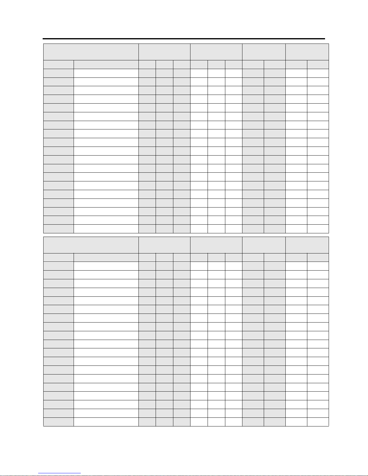
The width measurement (W) is in the direction across the chest of the user as positioned in the machine performing the exercise.
EEEENNNNGGGGLLLLIIIISSSSH
HH
H
U
UUUNNNNIIIITTTTSSS
S
AAAAT
TT
T R
R R
RE
EEESSSSTTT
T
((((
IIIINNNN.)
.).)
.)
DDDDU
UUURRRRIIIINNNNGGG
G E
E E
EX
XXXEEEERRRRCCCCIIIISSSSEEE
E
((((
IIIINNNN.)
.).)
.)
MMMMA
AAACCCCHHHHIIIINNNNEEE
E
WWWW
EEEEIIIIGGGGHHHHTTTT (
( (
(L
LLLBBB
B.)
.).)
.)
FFFFL
LLLOOOOOOOORRR
R L
L L
LO
OOOAAAADDD
D
((((
LLLLBBBB./
././
./S
SSSQQQ
Q.
..
.F
FFFTTT
T.)
.).)
.)
MMMMO
OOODDDDEEEELLL
L D
DD
DE
EEESSSSCCCCRRRRIIIIPPPPTTTTIIIIOOOONNN
N L
LL
L WWWW HHHH LLLL WWWW HHHH RRRRE
EEEGGG
G.
..
. OOOOP
PPPTTT
T.
..
. RRRRE
EEEGGG
G.
..
. OOOOP
PPPTTT
T
XL0100 Leg Extension 57 45 57 7 4 45 57 399 479 76 91
XL0200 Seated Leg Curl 68 47 57 73 47 57 424 504 71 84
XL0300 Leg Press 75 49 66 75 49 66 617 717 37 43
XL0400 Inner/Outer Thigh 67 29 57 67 74 57 464 544 44 51
XL0500 Triceps Extension 38 50 57 49 50 57 337 397 45 53
XL0600 Biceps Curl 38 50 57 46 50 57 368 428 55 64
XL0700 Shoulder Press 58 56 57 58 56 78 413 493 48 57
XL0800 Lateral Raise 35 48 57 35 54 57 310 370 48 58
XL0900 Seated Chest Press 46 56 57 49 56 57 410 490 63 75
XL1000 Pec F ly/Rear Delt 64 57 74 68 57 74 435 515 44 52
XL1100 L at Pu lldown 56 50 93 56 50 93 429 509 46 54
XL1200 Seated Row 55 49 57 55 49 57 406 486 39 46
XL1300 Lower Back 42 47 57 47 47 57 413 493 56 67
XL1400 Abdominal 38 46 57 38 46 57 325 385 42 50
XL1500 Triceps Pushdown 52 46 57 52 46 57 382 462 51 62
XL1600 Inc line Chest Press 75 60 57 75 60 57 445 525 36 42
XL1700 Rotary Torso 35 49 57 39 54 57 356 416 49 57
XL1800 Horizontal Leg Curl 62 43 57 63 43 57 366 446 60 73
XL1900 Low Cable Row 78 41 74 78 41 74 422 502 33 40
MMMMEEEETTTTRRRRIIIIC
CC
C
U
UUUNNNNIIIITTTTSSS
S
AAAAT
TT
T R
R R
RE
EEESSSSTTT
T
((((
CCCCMMMM.)
.).)
.)
DDDDU
UUURRRRIIIINNNNGGG
G E
E E
EX
XXXEEEERRRRCCCCIIIISSSSEEE
E
((((
CCCCMMMM.)
.).)
.)
MMMMA
AAACCCCHHHHIIIINNNNEEE
E
WWWW
EEEEIIIIGGGGHHHHTTTT (
( (
(K
KKKGGG
G.)
.).)
.)
FFFFL
LLLOOOOOOOORRR
R L
L L
LO
OOOAAAADDD
D
((((
KKKKGGGG./
././
./S
SSSQQQ
Q.
..
.M
MM
M.)
.).)
.)
MMMMO
OOODDDDEEEELLL
L D
DD
DE
EEESSSSCCCCRRRRIIIIPPPPTTTTIIIIOOOONNN
N L
LL
L WWWW HHHH LLLL WWWW HHHH RRRRE
EEEGGG
G.
..
. OOOOP
PPPTTT
T.
..
. RRRRE
EEEGGG
G.
..
. OOOOP
PPPTTT
T
XL0100 Leg Extension 145 114 145 188 114 145 181 217 370 444
XL0200 Seated Leg Curl 173 119 145 185 119 145 192 229 347 413
XL0300 Leg Press 191 124 168191124168 280 326 180 209
XL0400 Inner/Outer Thigh 170 74 145 170 188 145 211 247 214 251
XL0500 Triceps Extension 97 127 145124127145 153 180 221 260
XL0600 Biceps Curl 97 127 145 117 127 145 167 194 267 311
XL0700 Shoulder Press 147 142 145 147 142 198 188 224 235 280
XL0800 Lateral Raise 89 122 145 89 137 145 141 168 236 282
XL0900 Seated Chest Press 117 142 145 124 142 145 186 222 308 368
XL1000 Pec F ly/Rear Delt 163 145 188 173 145 188 197 234 216 256
XL1100 L at Pu lldown 142 127 236 142 127 236 195 231 223 264
XL1200 Seated Row 140 124 145140124145 184 221 189 226
XL1300 Lower Back 107 119 145 119 119 145 188 224 276 329
XL1400 Abdominal 97 117 145 97 117 145 148 175 207 245
XL1500 Triceps Pushdown 132 117 145 132 117 145 173 210 250 303
XL1600 Inc line Chest Press 191 152 145 191 152 145 202 238 176 207
XL1700 Rotary Torso 89 124 145 99 137 145 162 189 239 279
XL1800 Horizontal Leg Curl 157 109 145 160 109 145 166 202 292 356
XL1900 Low Cable Row 198 104 188 198 104 188 192 228 163 194
LAYOUT AND SPACING - MACHINE DIMENSIONS & WEIGHTS
7
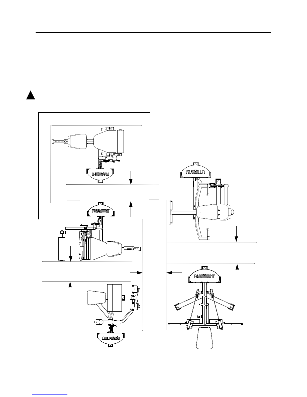
It is recommended to leave a space of 24 inches (61 cm.) around the machine at its
maximum exercise dimensions. The spacing may be less if the machine is positioned next to
a wall, or upright-to-upright with another machine so as to prevent a user from passing
through the area. If the spacing is t o be less than the recommended 2 4 inches (6 1 cm.), then
it should be less than 12 inches (31 cm.) so as to prevent users from passing through the
area.
DO NOT install any fitness equipment near a pool, hot tub or other damp locations. Corrosion
caused by installation in these locations can lead to premature failure of components.
!
WALL
12” (31 cm.) or less
WALL
24” (61 cm.) or more OR
12” (31 cm.) or less
24” (61 cm.) or more
24” (61 cm.) or more
24”
or
more
(61 cm.)
LAYOUT AND SPACING

8
RRRRE
EEEQQQQUUUUIIIIRRRREEEEDDD
D T
T T
TO
OOOOOOOLLLLSSS
S
UUUUN
NNNPPPPAAAACCCCKKK
K
T
TTTHHHHEEE
E H
H H
HA
AAARRRRDDDDWWWWAAAARRRREEE
E B
B B
BA
AAAGGG
G
FOR SAFETY REASONS, THE FOLLOWING STEPS REQUIRE THE ASSISTANCE OF MORE THAN ONE
FOR SAFETY REASONS, THE FOLLOWING STEPS REQUIRE THE ASSISTANCE OF MORE THAN ONE FOR SAFETY REASONS, THE FOLLOWING STEPS REQUIRE THE ASSISTANCE OF MORE THAN ONE
FOR SAFETY REASONS, THE FOLLOWING STEPS REQUIRE THE ASSISTANCE OF MORE THAN ONE
PERSON.
PERSON.PERSON.
PERSON.
After the machine is in position on a level surface, unpack the hardware bag attached to the
machine. In this bag you will find:
7/32” allen wrench. Used for guide rod bracket.
Wrenches (9/16”, 7/8” and 15/16” or an adjustable
crescent wrench). Used for guide rod bracket, cable bolt, and
cable nut.
Rubber mallet, used for end caps.
PPPPA
AAARRRRTTT
T #
# #
# DDDDE
EEESSSSCCCCRRRRIIIIPPPPTTTTIIIIOOOONNN
N
B751 Non-slip molded feet.
B1216 1” hole plugs.
B470 Weight stack selector pin with
lanyard.
!
INSTALLATION AND ASSEMBLY

9
INSTALLATION AND ASSEMBLY
FFFFO
OOOOOOOTTT
T I
I I
IN
NNNSSSSTTTTAAAALLLLLLLLAAAATTTTIIIIOOOONNN
N
1. To install the feet, ti lt the machine
to one side by pushing on the
upright or frame.
2. Place one of the feet onto the
lower f rame t ube as s how n. Ma ke
sure that the end caps are seated
in the frame tube before installing
the foot.
3. Lower the machine then ti lt the
machine towards another s ide.
4. Install another foot. Repeat until
all of the feet have been ins talled.
WWWWE
EEEIIIIGGGGHHHHTTT
T S
S S
ST
TTTAAAACCCCKKK
K I
I I
IN
NNNSSSSTTTTAAAALLLLLLLLAAAATTTTIIIIOOOONNN
N
1. Weight plates are packaged (4) per box and are marked with the quantity and weight of
the plates. The various configurations are shown below.
MOLDED FOOT
Make sure END
CAP is installed
Standard
170 LB.
(16) x 10lb. plates
4 boxes of B1602
Optional
250 LB.
(16) x 15lb. plates
4 boxes of B1603
Optional
310 LB.
(20) x 15lb. plates
5 boxes of B1603
Standard
210 LB.
(20) x 10lb. plates
5 boxes of B1602
Standard
130 LB.
(12) x 10lb. plates
3 boxes of B1602
Optional
190 LB.
(12) x 15lb. plates
3 boxes of B1603
10 LB. Weight Plate Box
Part Number: B1602
Comprised of
(4) x 10 lb. Weight Plates
15 LB. Weight Plate Box
Part Number: B1603
Comprised of
(4) x 15 lb. Weight Plates
Weight Stack Configurations

10
2. Review the equipment order to determine the correct w eight stack conf iguration of each
machine. Us e the following table to assist you in noting your configuration.
3. Disconnect the cable from the cap plate/select or bar, remove the bolts holding the guide
rod bracket and tilt the guide rods forward as shown on the following page.
4. Slide the guide rod bracke t an d th e cap plat e/selec t or bar upw ard and off t he gu ide rods.
On the XL0200, XL0500, XL1400, XL1500 and XL1800, remove the hardware from the
first hole in the selector bar (directly under the cap plate). Set the hardware aside.
5. Slide each weight plate onto the guide rods.
6. After installing all of the weights, slide the cap
plate/selector bar back onto the guide rods.
Ensure that the label is faci ng you.
7 . On the XL0200, XL0500, XL1400, X L1500
and XL1800, re-assemble the hardware
removed in Step 4. according to the diagram
shown. Slide the sleeve into the first hole in
the selector bar. Attach the first weight to the
selector bar.
MMMM
AAAACCCCHHHHIIIINNNNEEEE D
DD
DE
EEESSSSCCCCRRRRIIIIPPPPTTTTIIIIOOOONNN
N S
SS
ST
TTTAAAANNNNDDDDAAAARRRRDDD
D O
OO
OP
PPPTTTTIIIIOOOONNNNAAAALLL
L
XL0100 Leg Extension 170 lb. (77 kg.) 250 lb. (114 kg.)
XL0200 Seated Leg Curl 170 lb. (77 kg.) 250 lb. (114 kg.)
XL0300 Leg Press 210 lb. (95 kg.) 310 lb. (141 kg.)
XL0400 Inner/Outer Thigh 170 lb. (77 kg.) 250 lb. (114 kg.)
XL0500 Triceps Extension 130 lb. (59 kg.) 190 lb. (86 kg.)
XL0600 Biceps Curl 130 lb. (59 kg.) 190 lb. (86 kg.)
XL0700 Shoulder Press 170 lb. (77 kg.) 250 lb. (114 kg.)
XL0800 Lateral Raise 130 lb. (59 kg.) 190 lb. (86 kg.)
XL0900 Seated Chest Press 170 lb. (77 kg.) 250 lb. (114 kg.)
XL1000 Pec Fly/Rear Delt 170 lb. (77 kg.) 250 lb. (114 kg.)
XL1100 Lat Pulldown 170 lb. (77 kg.) 250 lb. (114 kg.)
XL1200 Seated Row 170 lb. (77 kg.) 250 lb. (114 kg.)
XL1300 Lower Back 170 lb. (77 kg.) 250 lb. (114 kg.)
XL1400 Abdominal 130 lb. (59 kg.) 190 lb. (86 kg.)
XL1500 Triceps Pushdown 170 lb. (77 kg.) 250 lb. (114 kg.)
XL1600 Incline Chest Press 170 lb. (77 kg.) 250 lb. (114 kg.)
XL1700 Rotary Torso 130 lb. (59 kg.) 190 lb. (86 kg.)
XL1800 Horizontal Leg Curl 170 lb. (77 kg.) 250 lb. (114 kg.)
XL1900 Low Cable Row 170 lb. (77 kg.) 250 lb. (114 kg.)
INSTALLATION AND ASSEMBLY
Sleeve
Cap plate
Step 7.

11
INSTALLATION AND ASSEMBLY
Cap Plate/
Guide Rod
Cable
TILT
Bracket
Selector Bar
Adder
Weight
Adder
Weight
Bracket
STEP #9.
OPTIONAL
Adder Weight
Bushing
Long side
of
Pull Pin
FORWARD

12
INSTALLATION AND ASSEMBLY
8. If you DID NOT order the Adder Weight Option, proceed to Step #10.
9. INSTALLATION OF TH E OPTIONAL ADDER WEIGHT SYSTEM:
•Slide the adder weight onto the guide rods as shown in the “OPTIONAL ADDER
WEIGHT” diagram on the previous page. Make sure that the long end of the bushing
faces down and that the pull pin faces the user. Insert the cable through the hole in
the adder weight.
• Assemble the adder weight bracket and guide rod bracket as shown.
10. Tilt the guide rods back to vertical and re-attach the gu ide rod bracket to the u pright.
IF
IFIF
IF the opti onal adder weight w as in stalled , secure i t in pl ace on t he adder weight brack et.
Make sure that the pull pin on the adder weight lines up with and freely passes through
the retaining hole in the adder weight bracket. You may need to reposition the adder
weight bracket slightly to ensure this.
11. Check the cable to ensure that it is
tracking in all of the pulleys and that the
cap plate/selector bar is sitting flush on the
top weight. Before re-attaching the cable to
the cap plate/selector bar assembly, insert
the selector pin lanyard ring between the
cable bolt head and the cable nut as shown.
12. Re-attach the cable to the cap
plate/selector bar and adjust the cable
tension so that th e cap/plate ba rely lifts o ff
of the first weight plate. Cycle the machine
with a light we ight to ensure that the
movement is smooth. Verify that the
selector pin can be inserted into the bottom
weight of the weight stack. If the selector
pin does not insert freely, loosen the cable
tension slightly.
13. Be sure that the dimension from under the
bolt head to the bottom of the cable nut
DOES NOT exceed 1-3/8” (35 MM.) as
shown. With the cable tension properly
adjusted, tighten the cable nut.
Lanyard Ring
Cable Bolt
Cable Nut
Selector
Pin Holder
Selector pin
with lanyard
WARNING
1. MAKE S U RE selecto r pin is
inserted completely. Use only
the Paramount pin shown.
2. Bolt height must not exceed
1-3/8”. Check regu larly. MAKE
SURE locking nut is tight.
ASTM F1749 P/N B2442
STORE
STORESTORE
STORE
SELECTOR PIN
SELECTOR PINSELECTOR PIN
SELECTOR PIN
HERE
HEREHERE
HERE
MAXIMUM
MAXIMUMMAXIMUM
MAXIMUM
Height
Under Nut to
Bolt Head
MAX
1-3/8” (35mm)
4
-
1
/
4
”
(
1
0
8
m
m)
Paramount Pin B 470
!!!!
1-3/8” (35mm)
MAX!
Cable Bolt
Cable Nut

13
WWWWE
EEEIIIIGGGGHHHHTTT
T S
S S
ST
TTTAAAACCCCKKK
K L
L L
LA
AAABBBBEEEELLL
L I
I I
IN
NNNSSSSTTTTAAAALLLLLLLLAAAATTTTIIIIOOOONNN
N
Locate the weight stack labels packed with your machine order. For your reference, a list of
weight stack labels and their correspo nding part numbers is shown below:
* Kilogram (KG.) labels are available upon request.
Note that the 130 lb. and 190 lb. weight stacks (wh ich have 12 weight plates each) use
the same labels as the 170 lb. and 250 lb. weight stacks (w hich have 16 weight plates
each). When installing labels on the 130 lb. and 190 lb. weight stacks, discard the last
4
numbers from the label.
To install the weight stack labels:
1. Verify tha t the co rrect weight stack is
properly installed on the machine.
2. With a clean, dry cloth, wipe the front
surface of the weight s with rubbin g
alcohol and allow the weights to dry
completely. Make sure that there is no
lint on the su rface.
3. Remove the backing from the label.
Align the top edge of the label with the
top edge of the weights and the side
of the label with the outside edge of
the selector pin holes.
4. Verify that the label strip is straight and
remove the liner. As the line r comes
off the label, press and rub each label
into place.
5. IMPORTANT!
IMPORTANT!IMPORTANT!
IMPORTANT! DO NOT attempt to “test”
the integrity of t he labels after they
have been installed. The adhesive on
the labels requires 72 hours to cure.
Weight St ack
Weight St ackWeight St ack
Weight St ack 130 lb.
130 lb.130 lb.
130 lb.
(12) x 10 lb.
190 lb.
190 lb.190 lb.
190 lb.
(12) x 15 lb.
170 lb
170 lb170 lb
170 lb.
(16) x 10 lb.
250 lb.
250 lb.250 lb.
250 lb.
(16) x 15 lb.
210 lb.
210 lb.210 lb.
210 lb.
(20) x 10 lb.
310 lb.
310 lb.310 lb.
310 lb.
(20) x 15 lb.
Label Part #
Label Part #Label Part #
Label Part # B2170 B2172 B2170 B2172 B2071 B2073
WARNING
1. MAKE SUR E selector pin is
inserted completely. Use only
the Paramount pin shown.
2. Bolt height must not exceed
1-3/8”. Check regular ly. MAKE
SURE locking nut is tight.
ASTM F1749
P/N B2442
STORE
STORESTORE
STORE
SELECTOR PIN
SELECTOR PINSELEC TOR PIN
SELECTOR PIN
HERE
HEREHERE
HERE
MAXIMUM
MAXIMUMMAXIMUM
MAXIMUM
Height
Under Nut to
Bolt Head
MAX
1-3/8” (35mm)
4
-
1
/
4
”
(
1
0
8
m
m)
Paramount Pin B 470
!!!!
Individual
Labels
Liner
Align with
outside
edge of
pin holes
INSTALLATION AND ASSEMBLY

14
OPTIONAL F
OPTIONAL FOPTIONAL F
OPTIONAL FR
RRROOOONNNNTTT
T P
P P
PA
AAANNNNEEEELLL
L K
K K
KI
IIITTT
T
If you have purchased the optional front panel kit for the upright, it should be installed now.
Each machine requires (1) front panel option (depending upon the machine model). The
components included with the kit are s hown below:
FFFFR
RRROOOONNNNTTT
T P
P P
PA
AAANNNNEEEELLL
L O
O O
OP
PPPTTTTIIIIOOOONNNNSSS
S KIT #
KIT #KIT #
KIT #
Fro nt Panel, for sta nd ar d up ri ght (used
on all machines except those li sted
below)
Single panel part number: S518
FPK
Front Panel for:
XL0300 (Leg Press)
XL1000 (Pec Fly/Rear Delt)
Single panel part number: S518A
FPK-LP
Front Panel for:
XL1100 (Lat pull).
Single panel part number: S518B
FPK-LAT
Each of the above listed Front Panel Kits contains a hardware pack (part number
HW-FPK). The following components are included in the pack.
BBBBR
RRRAAAACCCCKKKKEEEETTTTSSS
S & H
& H & H
& HA
AAARRRRDDDDWWWWAAAARRRREEE
E P
PP
PA
AAARRRRTTT
T #
# #
#
Long Bracket (qty. 4) 9004951
Short Bracket (qty. 2) 9004949
Rubber Insert (qty. 8) C 775
10-32 X 1” Phillips Head Screw (qty. 8) C 904
48”
57”
65”
INSTALLATION AND ASSEMBLY

15
1. Remove the hardware
holding the c urved rear
cover in place. DO NOT
remove the cover.
Assemble the brackets
and hardware as shown.
TIP: When assembli ng
the screw (C904) , press
on the bracket firmly to
prevent the rubber
insert (C 775) from
turning. Fully
tighten the
screws.
2. Assemble the front
panel as shown.
TIP: When assembli ng
the screw (C904) press
on the panel (S518) to
prevent the rubber
insert (C 775) from
turning. Fully
tighten the
screws.
9004951
C775
C740
(Reuse nut from
rear cover)
Typical for bottom bracket.
C905
(Reuse screw fr om
rear cover)
C775
9004949
C904
C775
C-904
(S 518A for XL-300 &
XL-1000)
S 518 for standard up right
(S 518B for XL1100)
INSTALLATION AND ASSEMBLY

16
OPTIONAL F
OPTIONAL FOPTIONAL F
OPTIONAL FO
OOORRRREEEEIIIIGGGGNNN
N L
L L
LA
AAANNNNGGGGUUUUAAAAGGGGEEE
E L
L L
LA
AAABBBBEEEELLLLSSS
S
If you have purchased optional foreign language label kits, they can be installed now. Each
machine requires (1) set of labels. The kits include all of the warning and procedure labels
and are available in either French, German, or Spanish. Also available are Kilogram (KG.)
weight stack labels.
Place the warning labels in close proximity to the English versions of the labels.
The procedure label can be installed on the inside surface of the weight stack shroud or on
the face of the front panel if the Optional Front Panel Kit was installed.
To install the KG. weight labels, follow the same instructions shown on page -13.
AAAAN
NNNCCCCHHHHOOOORRRRIIIINNNNGGG
G
T
TTTHHHHEEE
E M
M M
MA
AAACCCCHHHHIIIINNNNEEEESSS
S
T
TTTOOO
O
T
TTTHHHHEEE
E F
F F
FL
LLLOOOOOOOORRR
R
If desired, the machines in the Performance XL line can be anchored into position. Holes in
the base frame have been provided for bolts to be used to fasten the machines to the floor
(see below).
Due to the wide variation of flooring on which the machines can be installed, contact a
qualified contractor to determine the appropriate fastening method.
FFFFI
IIINNNNAAAALLL
L A
A A
AS
SSSSSSSEEEEMMMMBBBBLLLLYYY
Y
1. Insert the plugs provided in the hardware bag into the holes in the base frame as shown.
2. Lubricate the guide rods with a teflon spray lubricant such as Tri-Flow
TM
.
3. Inspect the machine. Check and tighten ALL fasteners and cable fittings as required.
4. Make sure that the machine functions cor r ectly and smoothly.
Provision for
anchor bolt
(typical)
1” Diameter
Hole Plug
B 1216
Drill through molded foot
INSTALLATION AND ASSEMBLY

17
RRRRE
EEEPPPPLLLLAAAACCCCEEEEMMMMEEEENNNNTTT
T P
P P
PA
AAARRRRTTTTSSS
S: C
: C: C
: CA
AAABBBBLLLLEEEESSS
S
A
AAANNNNDDD
D U
U U
UP
PPPHHHHOOOOLLLLSSSSTTTTEEEERRRREEEEDDD
D P
P P
PA
AAADDDDSSS
S
CCCCA
AAABBBBLLLLEEEESSS
S
Paramount recommends that the cable ends be inspected daily
and that the area that passes over the pulle ys be inspect ed weekly.
Remove the view port plugs and inspect the cable while someone
cycles the machine. Replace the cable at the fi rst sign of wear or on
an annual basis. Refer to the General Maintenance Manual.
Shown to the righ t is the routin g for the cable through the upright. If
a machine must be disassembled, disconnect the cable at the
machine side, leaving the section of cable that is routed through
the upright, in tact.
Remove the view port plugs to assist in routing the cable as well as
verifying that the c able is in the pulley groove. After installation,
make sure that the machine functions smooth ly and that all
pulleys rotate.
MMMMO
OOODDDDEEEELLL
L D
DD
DE
EEESSSSCCCCRRRRIIIIPPPPTTTTIIIIOOOONNN
N M
MM
MA
AAAIIIINNN
N C
C C
CA
AAABBBBLLLLEEE
E#
##
# AAAAU
UUUXXX
X. C
. C. C
. CA
AAABBBBLLLLEEE
E #
# #
# SSSSE
EEEAAAATTT
T P
P P
PA
AAADDD
D#
##
# TTTTO
OOORRRRSSSSOOO
O P
P P
PA
AAADDD
D#
##
# AAAAU
UUUXXX
X. P
. P. P
. PA
AAADDD
D #
# #
#
XL0100 Leg Extension LECAB04000 N/A LESPD04000X 9004970X 9002880X
XL0200 Seated Leg Curl LCCAB04000 N/A LESPD04000X 9004970X 9002880X
9000660x
XL0300 Leg Press LPCBL04000 N/A LPPAD04000X LPPAD04010X N/A
XL0400 Inner/Outer Thigh IOCAB04000 N/A IOSPD04000X IOBPD04000X IOTPD04000X (2)
XL0500 Triceps Extension TRCAB04000 N/A 9004990X TRPAD04000X TRPAD04020X
XL0600 Biceps Curl ACCAB04000 N/A 9004990X N/A ACPAD04000X
XL0700 Shoulder Press SPCAB04000 N/A 9004990X 9004970X N/A
XL0800 Lateral Raise DLCAB04000 DLCAB0401 0 9004990X SRCPD04000X SRCPD04000X (2)
XL0900 Che st Press CPCAB04000 N/A 9004990X 9004970X N/A
XL1000 Pec Fly/Rear Delt VBCAB04000 VBCAB04010 9004990X VBBPD04000X N/A
XL1100 L at Pu lldown LATCAB04000 LATCAB04010 9004990X N/A 9092083X (2)
XL1200 Seated Row SRCAB0400 N/A 9004990X N/A SRCPD04000X
XL1300 Lower Back LBCAB04000 N/A LBSPD04000X LBBPD04000X 9002880X
XL1400 Abdominal ABCAB04000 N/A 9004990X IOTPD04000X 9002880X
XL1500 Triceps Pushdown STCAB04000 N/A 9004990X 9004970X N/A
XL1600 Inc line Chest ICCAB04000 N/A 9004990X ICPAD04000X N/A
XL1700 Rotary Torso RTCAB04000 N/A RTSPD04000X 3000BPD000X
QTY. (2)
RTPAD04010X (2)
SRCPD04000X (2)
XL1800 Horizontal Leg Curl HCCAB04000 N/A HCPAD04010X HCPAD04000X 9002880X
XL1900 Low Cable Row RWCAB05000 RWCAB05010 RWSPD05000X N/A N/A
MACHINE MAINTENANCE
View Port Plug

18
XL0300 L
XL0300 LXL0300 L
XL0300 LE
EEEGGG
G P
P P
PR
RRREEEESSSSSSS
S R
R R
RO
OOOLLLLLLLLEEEERRR
R A
A A
AD
DDDJJJJUUUUSSSSTTTTMMMMEEEENNNNTTT
T
The XL-300 Leg Press is provided with an adjustable roller feature that ensures smooth
operation. This adjustment is preset at the factory. However, if you need to disassemble the
machine and remove the seat assembly, the rollers must be re-adjusted.
Tools Required:
(2) - 5/16” allen wrenches
1-1/4” wrench (or large adjustable crescent wrench)
The adjustment is made using the roller clearance adjusters which are located on both the
left and right s ides of t he trolley. To make the adjustment, start by loosening the button head
cap screws in the center of the adjusters. Then use a wrench to rotate the adjuster so that
there is only a small gap of about 1/32” (1 mm) between one of the rollers and the rail.
Look down the length of the rail from the rear of the machine at the position of the upper
and lower rollers relative to the rail. Adjust both the left and right roller. Once the correct
position is set, hold the wrench in place and use the allen wrenches to tighten the button
head screws.
Roller Clearance Adjuster
Leave a small gap,
between either the
and the rail.
Wrench
Trolley
Upper
Roller
Lower
Roller
View looking
down the rail
from the rear
Rail
1/32” (1 MM.),
top or bottom roller
MACHINE MAINTENANCE

19
LLLLA
AAABBBBEEEELLLLSSS
S
The following are the Warning and Procedure labels required for each machine. If any of
these labels are missing or become damaged, Paramount will replace them free of charge.
WARNING
!
SERIOUS INJURY CAN OCCUR ON
THIS EQUIPMENT. FOLLOW THESE
PRECAUTIONS TO HELP AVOID INJURY.
1. BEFORE USING: Read all of the
warnings and obtain instruction on the
use of this machine. Use only for the
intended exercise. DO NOT modify the
machine.
2. Get a medical exam before beginning an exercise program.
3. Keep body and clothing clear of all
moving parts. DO NOT wear anything
loose or dangling.
4. Inspect the machine before use.
DO NOT use if it appears damaged.
DO NOT try to fix any machine. Notify
staff immediately .
5. INSPECT MACHINE DAILY for
loose, worn or damaged parts. Tighten
and adjust all loose parts. Replace
any part or label at first signs of wear.
Inspect all cables and their connections closely . If you are in doubt about
any part, DO NOT use the machine
until the part is replaced.
6. Inspect cables and connections
before using the machine. DO NOT
use this machine if any part appears
worn or damaged.
7. Be certain that weight pin B460 is
completely inserted. Use only the pin
provided by the manufacturer. If
unsure, seek assistance.
8. NEVER pin the weights or top plate
into an elevated position. DO NOT
use the machine if found in this condition. DO NOT try to fix. Seek assistance.
9. Use only the incremental weights
supplied by the manufacturer. DO NOT
use dumbbells or other means to add
resistance to the machine.
10. NEVER allow children near this
machine. Supervise teenagers.
11. DO NOT REMOVE THIS LABEL.
REPLACE IF DAMAGED.
P/N B2060
ASTM F1749
B2060
MAINTENANCE
SCHEDULE
Check the integrity and function
of the following items. Replace
all worn components immediately.
D
A
I
L
Y
W
E
E
K
L
Y
Cables - Check tension end
fittings, and coating
Check tightness of
weight stack locking nut.
REPLACE CABLES ANNUALLY
Upholstery - Wipe down and dry.
Clean and condition.
Frame - Wipe with water dampened
cloth and dry completely.
DO NOT leave parts moist.
Polish/Wax
Chrome - Wipe with water dampened
cloth and dry co m p le tely.
DO NOT leave parts moist.
Polish/Wax
Nuts/Bolts/Fasteners - Tighten
and/or adjust as needed.
Guide Rods - Lubricate and clean
Linear Rods - Lubricate and clean
Seat Sleeves - Lubricate and clean
Adjustments/ Locking Pins/
Tightening Knobs
Weight Stack Pin
Warning/Instruction Labels
Springs
Anti-Skid
Hand Grips
Order Paramount Service Kit P/N KIT-01
for recommended maintenance products
PARAMOUNT CUST OMER SERVICE
1-800-721-2121
P/N B2315
B2315
WARNING LABELS

20
WARNING LABELS
WARNING
!
SERIOUS INJURY CAN OCCUR
ASTM F1749
P/N B2051
ON THIS EQUIPMENT IF THE
CABLES AND THEIR ATTACHMENT COMPONENTS ARE NOT
INSPECTED OFTEN. REPLACE
AT FIRST SIGNS OF WEAR.
B2051
WARNING
SERIOUS INJU RY CAN OCCUR ON THIS EQU IP M E N T IF
ASTM F1749
P/N B2065
THE PIN IS NOT COMPLETELY INSERTED BEFORE USE.
!
B2065
P/N B1299
B1299
USE THIS LAT BAR ON PARAMOUNT LAT STATIONS
WITH 310 POUNDS OR LESS.
INSPECT CABLE FITTING AND CONNECTIONS PRIOR
TO USE. BE CERTA IN THAT THE CONNECTIONS ARE SECURE.
FAILURE TO FOLLOW THESE PR O C EDURES MAY RESULT
IN SERIOUS INJURY.
ASTM F1749
WARNING
!
WARNING
1. MAKE SURE selector pin is
inserted com pletely. Use only
the Paramount pin shown.
2. Bolt height must not exceed
1-3/8”. Check regularly. MAKE
SURE locking nut is tight.
ASTM F1749
P/N B2442
STORE
STORESTORE
STORE
SELECTOR PIN
SELECTOR PINSELECTOR PIN
SELECTOR PIN
HERE
HEREHERE
HERE
MAXIMUM
MAXIMUMMAXIMUM
MAXIMUM
Height
Under Nut to
Bolt Head
MAX
1-3/8” (35mm)
!!!!
Paramount Pin B 470
4
-
1
/
4
”
(
1
0
8
mm
)
B2442
WARNING
!
MOVING PARTS
ASTM F1749
P/N B2064
STAY CLEAR!
B2064
WARNING
!
ASTM F1749
P/N B2083
B2083
SUPPORT WEIGHT
OF SEAT BY
GRASPING HANDLE
BEFORE ADJUSTING
SEAT POSITION
CAUTION
Move handle to
P/N B2445
!
B2445
the left a nd hold
it there when you
adjust the pad
21
HHHHO
OOOWWW
W
T
TTTOOO
O O
O O
OB
BBBTTTTAAAAIIIINNN
N S
S S
SE
EEERRRRVVVVIIIICCCCEEE
E
For warranty service, contact an Authorized Paramount Dealer or Paramount Customer
Service at 1-800-721-2121. Before you call, please have the following information ready:
•••• Model Number
Model NumberModel Number
Model Number
•••• Seria l Number
Serial NumberSerial Number
Serial Number
•••• Date of installation
Date of instal lationDate of instal lation
Date of instal lation
•••• A brief description of the problem
A brief descriptio n of the problemA brief descriptio n of the problem
A brief descriptio n of the problem
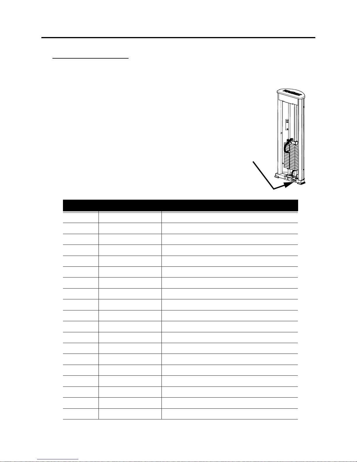
The space below is provided for you to record the model
and serial numbers of the equipment that you
purchased. Serial numbers are located near the bottom
of the upright.
Installation Date _____________________
MMMMA
AAACCCCHHHHIIIINNNNEEE
E D
DD
DE
EEESSSSCCCCRRRRIIIIPPPPTTTTIIIIOOOONNN
N R
RR
RE
EEECCCCOOOORRRRDDD
D S
S S
SE
EEERRRRIIIIAAAALLL
L N
N N
NU
UUUMMMMBBBBEEEERRRRSSS
S H
H H
HE
EEERRRREEE
E
XL0100 Leg Extension
XL0200 Seated Leg Curl
XL0300 Leg Press
XL0400 Inne r/Outer Thigh
XL0500 Triceps Extension
XL0600 Biceps Curl
XL0700 Shoulder Press
XL0800 Lateral Raise
XL0900 Seated Chest Press
XL1000 Pec Fly/Rear Delt
XL1100 Lat Pulldown
XL1200 Seated Row
XL1300 Lower Back
XL1400 Abdominal
XL1500 Triceps Pushdown
XL1600 Incline Chest Press
XL1700 Rotary Torso
XL1800 Horizontal Leg Curl
XL1900 Low Cable Row
Serial Number
SERVICE

22
NOTES

23
Paramount warrants to the original purchaser from a Paramount authorized dealer that
Paramount equipment or equipment from a Paramount authorized m anufacturing contractor will be
free from defects in material and workmanship under normal use and service for the following periods
and in the following respects:
LIFETIME WARRANTY
LIFETIME WARRANTYLIFETIME WARRANTY
LIFETIME WARRANTY - Welds, Weight Plates and Guide Rods
FIVE YEAR WARRANTY
FIVE YEAR WARRANTYFIVE YEAR WARRANTY
FIVE YEAR WARRANTY - Bronze Bushings, Sealed Rotat ing Beari ngs and Pulley Whee ls
ONE YEAR WARRANTY
ONE YEAR WARRANTYONE YEAR WARRANTY
ONE YEAR WARRANTY - Cables, Linear Bearings, Linear Shafts and all other components not
mentioned elsewhere in this warranty
NINETY DAY WARRANTY
NINETY DAY WARRANTYNINETY DAY WARRANTY
NINETY DAY WARRANTY - Upholstery and Grips
This limited warranty DOES NOT
DOES NOTDOES NOT
DOES NOT cover and no warranty is given with respect to:
• Products not manufactured by Paramount
• Products which are altered w i thout the express written consen t of Paramount
• Products purchased other than directly from Paramount or through a Paramount
Authorized Dealer.
All warranty periods begin to run from the da te of delivery to the original purchaser. The
obligation of Paramount unde r this warranty is limited to repairing or replacing warranted de fective
parts, as Paramount may elect, at Paramount's plant in Los An geles, California, without charge to
purchaser for either parts or labor. Purchaser is responsible for all transportation and insurance costs
on returned or replaced equipment to and from Paramount's plant in Los Angeles.
ANY IMPLIED WARRANTY, INCLUDING BUT NOT LIMITED TO THE IMPLIED WARRANTY OF
FITNESS FOR A PARTICULAR PURPOSE AND THE IMPLIED WARRANTY OF MERCHANTABILITY, IS
LIMITED TO ONE YEAR DURATION FROM THE DATE OF DELIVERY TO THE ORIGINAL PURCHASER.
SOME STATES DO NOT ALLOW LIMITATIONS ON HOW LONG AN IMPLIED WARRANTY LASTS, SO THE
ABOVE LIMITATION MAY NOT APPLY TO YOU. THE REMEDY OF REPAIR AND REPLACEMENT IS THE
EXCLUSIVE AND SOLE REMEDY OF THE PURCHASER. PARAMOUNT SHALL NOT BE LIABLE FOR ANY
SPECIAL, INCIDENTAL, CONTINGENT OR CONSEQUENTIAL DAMAGES OF ANY KIND, INCLUDING, BUT
NOT LIMITED TO, DAMAGE OF LOSS OF OTHER PROPERTY OR EQUIPMENT AND LOST PROFITS OR
REVENUE. SOME STATES DO NOT ALLOW THE EXCLUSION OR LIMITATION OF INCIDENTAL OR
CONSEQUENTIAL DAMAGES, SO THE ABOVE LIMITATION OR EXCLUSION MAY NOT APPLY TO YOU.
No action for breach of this written limited warranty or an implied warranty shall be
commenced more than one year after the accrual of the cause of action. This written limited warranty
is the complete, final and exclusive agreement of the parties with respect to the quality or
performance of the goods and any and all warranties and representations. No modifications of this
limited warranty or waiver of its terms shall be binding on either party unless approved in writing by an
authorized corporate officer of Paramount. This limited warranty gives you specific legal rights, and
you may also have other rights which may vary from state to state. Contact Paramount Fitness Corp.,
6450 E. Bandini Blvd., Los Angeles, California 90040-3185, for a list of authorized dealers or before
returning any defective equipment. Paramount Fitness Co rp. © 2004
PARAMOUNT FITNESS CORPORATION
PARAMOUNT FITNESS CORPORATIONPARAMOUNT FITNESS CORPORATION
PARAMOUNT FITNESS CORPORATION
6450 E. BANDINI BLVD., LOS ANGELES, CA 90040-3185 USA
6450 E. BANDINI BLVD., LOS ANGELES, CA 90040-3185 USA6450 E. BANDINI BLVD., LOS ANGELES, CA 90040-3185 USA
6450 E. BANDINI BLVD., LOS ANGELES, CA 90040-3185 USA
PARAMOUNT LIMITED WARRANTY

Paramount Fitness Corporation
6450 E. Bandini Blvd.
Los Angeles, CA 90040-3185
Phone: 1-323-721-2121 Fax: 323-724-2000
1-800-721-2121
www.paramountfitness.com
AM-XL.fm
REV:10/20/05
 Loading...