

Paramount Fitness Ultra UV2 Installation Manual
295 East Corporate Place • Suite 100 • Chandler, AZ 85225
Toll Free: 1.800.621.5886 • Phone: 480.893.7607 • Fax: 480.753.3397
Paramount@1Paramount.com • www.1Paramount.com
004-027-9000-00 REV 01 Publish 07/17/18 ECN_1584
INSTALLATION &
OPERATIONS MANUAL
When using this electrical equipment, basic safety precautions
should always be followed, including the following:
• Follow all applicable electrical codes.
• Turn off power at main source before making any electrical connections or servicing the unit.
• To reduce the risk of electric shock, injury or death disconnect unit from power supply
• Follow the instructions or risk of serious injury or death could occur!
• To reduce risk of injury, do not permit children to use this product unless they are closely
supervised at all times.
• Risk of electric shock. Install at least 5 feet (1.5m) from inside wall of pool, hot tub or spa using
nonmetallic plumbing.
• This product shall only be connected to a power supply receptacle protected by a ground fault
circuit interrupter.
UV EXPOSURE & PROTECTION:
UV-A and UV-B radiation can have adverse short and long term effects on the eyes and skin. Never
look directly at a UV lamp that is connected to a power source. Avoid UV skin exposure at all times.
WARNING
Pool, Spa & Pond
Water Sanitizer 4BJ1
EPA Registered
#084221-AZ-001
RISK OF INJURY
A) Replace damaged cord immediately.
B) Do not bury cord
C) Connect to a grounded, grounding type receptacle only.
DANGER
IMPORTANT SAFETY INSTRUCTIONS
READ AND FOLLOW ALL INSTRUCTIONS
SAVE THESE INSTRUCTIONS
2
Table of Contents
WELCOME ...................................................................................................................................................................... 2
ULTRA UV2 SYSTEM SIZING ................................................................................................................................... 3
POOL, SPA, FOUNTAIN, WATER FEATURE AND WATER FALL SIZING CHART ...............................3
LOCATING THE ULTRA UV2 UNIT ..........................................................................................................................4
INSTALLING INLET/OUTLET UNIONS ..................................................................................................................4
PLUMBING THE ULTRA UV2 UNIT ........................................................................................................................4
TYPICAL PLUMBING WITHOUT AND WITH BYPASS ..................................................................................5
PLUMBING THE ULTRA UV2 UNIT WITH OPTIONAL BYPASS VALVE ..................................................5
INSTALLING OPTIONAL FLOW SWITCH IF THE TOP OF THE UNIT IS BELOW WATER LEVEL ......5
PARALLEL PLUMBING WITHOUT AND WITH BYPASS ............................................................................6
MULTIPLE PORT PLUMBING FOR 3 LAMP UNITS WITHOUT AND WITH BYPASS ....................6
PROVIDING ELECTRICAL POWER TO THE ULTRA UV2 UNIT .................................................................6
ELECTRICAL BONDING ............................................................................................................................................7
WIRING INSTRUCTIONS ON THE ULTRA UV2 ...............................................................................................7
SYSTEM START-UP .......................................................................................................................................................8
NORMAL OPERATION ...............................................................................................................................................9
WINTERIZE / SERVICE OPERATION .................................................................................................................. 9
WINTERIZATION OF YOUR ULTRA UV2 UNIT .................................................................................................9
CONSUMER OPERATING INSTRUCTIONS QUARTZ TUBE MAINTENANCE ............................... 10
SCHEDULED UV LAMP(S) REPLACEMENT .................................................................................................. 12
TROUBLESHOOTING .............................................................................................................................................. 13
ULTRA UV2 PART NUMBERS ................................................................................................................................ 16
WELCOME
The Ultra UV2 unit is designed for use in swimming pools, spas, fountains, water features, waterfalls, fish
ponds and the like.
It is not designed for use in potable (drinking) water installations.
Use of this product in applications other than those indicated above
will void your warranty and could be harmful to your health or the
health of others.
WARNING
DANGER
CAUTION
WARNING
NOTICE
Indicates a hazardous situation
which, if not avoided, will result
in death or serious injury.
Indicates a hazardous situation
which, if not avoided, could result
in minor or moderate injury.
Indicates a hazardous situation
which, if not avoided, could
result in death or serious injury.
Is used to address practices
not related to physical injury.
Signal Words and Symbols Used In This Manual
This Owner’s Manual and Installation Guide contains specific precautions and symbols to identify safetyrelated information. You will find DANGER, CAUTION, WARNING and NOTICE symbols which require
special attention. Please read them carefully and follow these precautions as indicated! They will explain
how to avoid hazards that may endanger you or persons using or maintaining your pool or spa.
PLEASE REVIEW THE OWNER’S MANUAL AND INSTALLATION GUIDE IN ITS ENTIRETY AND
HEED ALL SAFETY INFORMATION. Failure to follow these instructions and warnings can result in
DEATH OR SERIOUS INJURY.
SAVE THESE IMPORTANT SAFETY INSTRUCTIONS
For the most current version of this install manual go to:
www.1paramount.com/support/download-manuals

3
GENERAL PRODUCT INFORMATION
Water circulates through the Ultra UV2 chamber and around the quartz tube where the UV-C lamp(s) (1
to 3 lamps depending on the model) are housed. The UV-C lamp emits a light wave spectrum (253.7 nm
wavelength) to immediately inactivate 99.9% of micro-organisms such as Crypto, Giardia, other single
celled waterborne microorganisms and algae which are resistant to chlorine. This provides a cleaner,
clearer swimming environment with zero harmful by-products and dramatically reduces the amount of
chlorine needed to maintain an adequate level of residual sanitizer. The Ultra UV2 unit has been sized to
produce these important UV rays in the same intensity as is required for Class A potable drinking water,
which is 30,000 micro watts/cm2 (30 mJ). Confirm the size unit your application needs by using the
sizing charts on page 3, to obtain the proper maximum system killing power.
Please note the minimum and maximum flow rates for each Ultra UV2 lamp configurations.
DO NOT USE THIS UNIT FOR POTABLE (DRINKING) WATER
SANITATION.
CAUTION
ULTRA UV2 SYSTEM SIZING
In order to ensure that your Ultra UV2 unit functions with the proper water exposure time to achieve the
desired water sanitation, it is important to provide the proper water flow rate through the Ultra UV2 unit. If
water passes through the unit too quickly, the microorganism’s exposure time to the UV lamp(s) produced
rays will not be sufficient to obtain the desired rate of sanitation. Please note that the minimum
posted flow rate must be met or exceeded to ensure proper system performance. The water
flow rate through the UV unit is governed by the piping of your water vessel and the size and output of
your circulation pump. Consideration to the application for the UV unit must be determined. Fish ponds,
as an example, have different requirements than swimming pools, spas, water features, fountains, or
waterfalls, as noted elsewhere in this manual.
FIRST STEP IN STARTING YOUR INSTALLATION
Inspect the Ultra UV2 unit for damage, paying close attention to the quartz tube.
POOL, SPA, FOUNTAIN, WATER FEATURE AND WATER FALL SIZING CHART
Fig. 2 Swimming pools and similar water vessels are simple to calculate. See chart below.
Ultra UV2 Part Number
Minimum
Flow Rate
(GPM) /
(m3/hr)
Maximum
Flow Rate
(GPM) /
(m3/hr)
Max
Pool Volume
12 Hr.
Turnover
(Gallons) /
(m3/hr)
Max
Pool Volume
8 Hr.
Turnover
(Gallons) /
(m3/hr)
Minimum
Operating
Pressure
(psi) / (bar)
Maximum
Operating
Pressure
(psi) / (bar)
004-422-2025-00
230V w/ 1 UV-C Lamp
004-422-2021-00
120V w/ 1 UV-C Lamp
10 / 2.27 46 / 10.4
33120 /
125.4
22080 /
83.6
5 / .345 50 / 3.45
004-422-2026-00
230V w/ 2 UV-C Lamps
004-422-2022-00
120V w/ 2 UV-C Lamps
20 / 4.54 80 / 18.2
57600 /
218.0
38400 /
145.4
5 / .345 50 / 3.45
004-422-2027-00
230V w/ 3 UV-C Lamps
004-422-2023-00
120V w/ 3 UV-C Lamps
*
30 / 6.81
*130 /
*29.5
93600 /
354.3
62400 /
236.2
5 / .345 50 / 3.45
All capacities are nominal Note: Multiple Ultra UV2 units installed in parallel can be used for flow rates
beyond those specified herein. (See page 6)
* Header size should be 2½" or 3" and split to two 2" pipe headers at the inlet and outlet connections.
(See page 6)
NOTICE
4
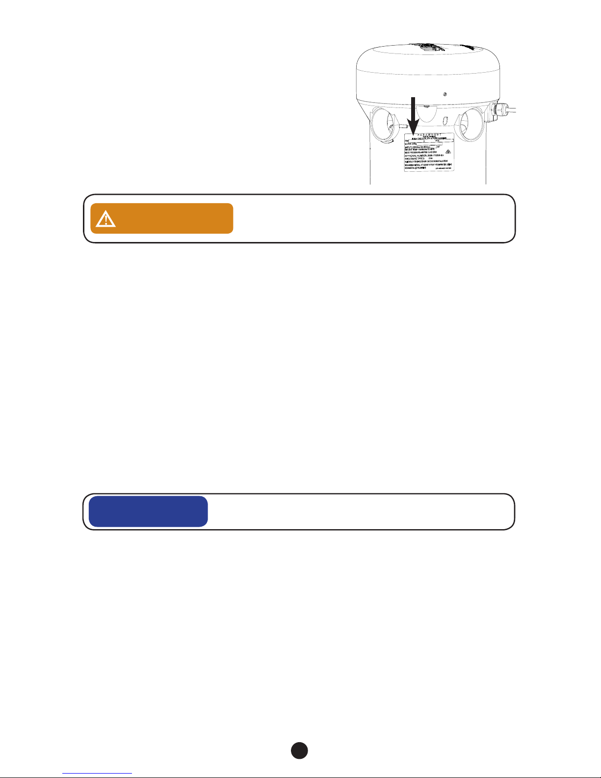
LOCATING THE ULTRA UV2 UNIT
Your unit can be installed indoors or outdoors. When
considering the location for your Ultra UV2 unit, keep it
close to your power source. Check the silver product label
for the voltage of the unit. The Ultra UV2 unit will need to
be powered from either a 120V/15A/50/60Hz or 230
V/15A/50/60Hz electrical circuit (which MUST match
the unit power requirement noted on the silver product
label on the Ultra UV2 unit). DO NOT CONNECT TO
ELECTRICAL POWER NOT SPECIFIED FOR YOUR
UNIT. Plug in units must be installed on a GFCI outlet. The
GFCI must be outdoor rated if installed outdoors. 230V
Ultra UV2 units can be wired for 120V or 230V.
DO NOT CUT OFF the plug from the 120V Ultra UV2 units and
hardwire it. This does not meet the U.L. installation method and voids
the U.L. listing.
WARNING
MOUNTING THE UV UNIT ON A SOLID BASE
Before you make the permanent plumbing connections be sure the ULTRA UV2 unit is on a solid level base
making sure your plumbing connections align. Make sure there is ample space above the unit for lamp
replacement. After making your plumbing connections, anchor the unit to the base using the four ¼” mounting
holes. FAILURE TO PROPERLY SECURE THE UNIT MAY CAUSE NOISE OR VIBRATION.
INSTALLING INLET/OUTLET UNIONS
The Ultra UV2 unit comes with female socket glue-in inlets and outlet openings. ABS to PVC
multipurpose glue and appropriate primer must be used to glue fittings into the ULTRA UV2 body. The
4 outlets (top) and 4 inlets (bottom) provide the most versatile piping alternatives for the installer. The
ULTRA UV2 unit comes with (2) unions (See page 16 for part numbers). Multiple inlets and outlets can
be used to the manage higher flow rates of 3 lamp units which come with 4 unions and 4 plugs.
NOTE: The use of multiple inlets/outlets will require additional unions. Use the plugs provided with the Ultra
UV2 in the unused inlets and outlets. To install the unions onto the Ultra UV2 unit, glue and insert the unions
spigot end into the inlet and outlet opening selected. Then, using the six plugs provided, glue the plugs into the
remaining unused plumbing openings. Hand tightening the union nuts until snug is sufficient. DO NOT OVER
TIGHTEN. Over tightening may break the molded plastic parts of the unions. Once you are confident that you
have installed the inlet and outlet union halves successfully, you will be ready to glue your plumbing into the
union sockets once the Ultra UV2 unit is positioned on the mounting surface.
A 24 hour cure time is required before pressure can be applied
to the Ultra UV2 unit.
NOTICE
PLUMBING THE ULTRA UV2 UNIT
All plumbing methods are illustrated with and without the bypass option. Your Ultra UV2 unit will need to
be plumbed into the circulation system. The Ultra UV2 unit must be installed directly after the filter.
Installing a bypass is not recommended. The only reasons for installing an Ultra UV2 bypass: 1. To allow
for removal of the UV unit, while still allowing the system to operate with water flowing through the bypass. 2. If
system pressure testing above 50 psi is required (max Ultra UV2 pressure is 50 psi/ 3.45 bar). The acceptable
reasons for removal include winterization, servicing, off site repairs and replacement. If a bypass is required
it must be installed & operated per instructions on pages 5 - 6. Before bypassing the Ultra UV2
for removal, turn off all pumps and allow the pool system’s pressure to drop to zero.
AN IMPROPERLY USED BYPASS INSTALLATION MAY NOT MEET THE
MINIMUM REQUIRED FLOW RATE AND COULD POTENTIALLY DAMAGE
THE ULTRA UV2 UNIT.
Fig. 3
Power
Requirement

5
PLUMBING THE ULTRA UV2 UNIT WITH OPTIONAL BYPASS VALVE
The only reasons for installing an Ultra UV2 with bypass valve:
1. To allow for removal of the UV unit for winterization, servicing, repairs, or replacement, while
still allowing water to flow through the system.
2. If system pressure testing above 50 psi is required (max Ultra UV2 pressure is 50 psi/ 3.45 bar).
A
INSTALLING OPTIONAL FLOW SWITCH IF THE TOP OF THE UNIT IS BELOW WATER LEVEL
The pressure switch will always be on if the Ultra UV2 unit is plumbed below water level. To prevent
damage to the unit and its surroundings an optional flow switch must be installed. If the Ultra UV2 unit is
plumbed on a bypass, the optional 2 inch Flow Switch (part #004-402-0010-00 for 220v or part #004421-3824-00 for 120v), must be on the outlet side of the Ultra UV2 unit and plumbed after the two way
valve and before the tee into the return line. Please refer to the instructions supplied with the flow switch for
plumbing and wiring.
B
Turn off the power at the main source before disconnecting
or connecting the Ultra UV2.
DANGER
GLUING PIPING TO THE UV UNIT
Two Inlet/Outlet unions are supplied on our 1 & 2 lamp units and 4 unions are supplied on 3 lamp units.. Your
PVC supply piping should be glued into the union tail pieces using an appropriate primer and ABS to PVC
cement. Inlet piping should be supported and should not rest solely upon the unions, to avoid stressing or
breaking the unions. Allow the glue to set following the glue manufacturers recommendations before pressure
testing. A minimum of 24 hours is recommended. Maximum test pressure for the Ultra UV2 is 50 PSI / 3.45 BAR
as noted on the silver label on the unit. If local codes require the pressure test to be higher than the max operating
pressure on the silver label use the bypass (if the unit is plumbed with a bypass) to allow the Ultra UV2 to be only
left at or below the max operating pressure.
Do not plumb the Ultra UV2 with a bypass unless absolutely needed.
Failure to follow the instructions can result in damage to the Ultra UV2
that is not covered by the warranty.
NOTICE
Strongly recommend using supplied unions.
NOTICE
Filter
To Heater
or Pool
Pump
TYPICAL PLUMBING WITHOUT AND WITH BYPASS
The inlet(s) is at the bottom of the unit and the outlet(s) at the top. The maximum operating pressure for the
Ultra UV2 is 50 PSI / 3.45 BAR. The minimum operating pressure is 5 PSI / .345 BAR. Please refer to the
silver label on the unit for max. operating pressure.
Optional bypass
fully closed
A
Optional Flow
Switch
B
Optional bypass valves fully open
into inlet port and from the outlet port
A
This pipe does not exist if bypass
valve is not installed
 Loading...