

Paramount Fitness PCC2000, PV3, Cyclean, Pool Valet, Vantage Owner's Manual
...
1
295 East Corporate Place • Suite 100 • Chandler, AZ 85225
Toll Free: 1.800.621.5886 • Phone: 480.893.7607 • Fax: 480.753.3397
Paramount@1Paramount.com • www.1Paramount.com
004-027-8742-00 REV052313
US and Foreign patents and patents pending –
www.paramountpools.com/patents/
Cleaning System Manual
For PCC2000, PV3, Cyclean, Pool Valet,
New Pool Valet, Vantage, Vanquish,
StepClean, SwingSweep and EcoPool
OWNER’S MANUAL

2
Congratulations! ............................................................................. 3
What You Need to Know .............................................................. 3
What is a Water Valve? ................................................................ 4-5
Unique Water Valve Features ...................................................... 6
Water Valve Parts Breakdown ..................................................... 7
Water Valve Instructions ............................................................... 8-15
How to Open the Water Valve ................................................ 8
Module Installation (6-port) ...................................................... 9-10
Module Installation (2-port, 3-port, 4-port) ........................... 11-12
Alignment Guide ....................................................................... 13
How to Close the Water Valve ................................................ 14
Run/Pause Switch ..................................................................... 15
Nozzles (Cleaning Heads) ............................................................ 16
Nozzle Removal/Installation ......................................................... 17-20
Optional Paramount Debris Canister ....................................... 21
Relationship with Pool Equipment .............................................. 22-25
Cleaning Systems Powered by the Filter Pump .................. 22
Cleaning Systems Powered by a Booster Pump ............... 23
Filters ............................................................................................. 23-24
Valves for a single Pump System ........................................... 24
Chlorinators, Tablet or Salt Systems, Ozone, Solar ............ 24-25
Operating Instructions .................................................................. 26
Troubleshooting Guide for Paramount In-Floor Systems ...... 27-29
Warranty Certificate ....................................................................... 30
Copyright © 2013 Paramount Pool & Spa Systems. All Rights Reserved.
Contact Paramount Pool & Spa Systems at 1.800.621.5886
TABLE OF CONTENTS

3
CONGRATULATIONS
Congratulations on your new pool and thank you for choosing one of
Paramount’s cleaning or circulation systems. This manual will address
all of Paramount’s systems, the PCC2000, PV3, Cyclean, Pool Valet,
New Pool Valet, Vantage, Vanquish, Step Clean, Swing Sweep, and Eco
Pool. Your system may also include a Paramount debris canister and
one or more of Paramount’s Drains (MDX-R3, MDX2, MDX, Buzztop
Channel Drain and/or SDX).
Your system’s performance will be maximized by adhering to the following operating instructions, and can be affected by seasonal weather
conditions that may require extended periods of operation. The cleaning performance directly relates to the type and design of your specific
Paramount system.
It is recommended you call your pool builder or a professional service
company if your pool requires attention.
WHAT YOU NEED TO KNOW

4
The Paramount water valve is fully
automatic and operates whenever the
pump it’s connected to is running.
Your Paramount Water Valve may be
connected to your filter pump or a
stand-alone “booster” pump.
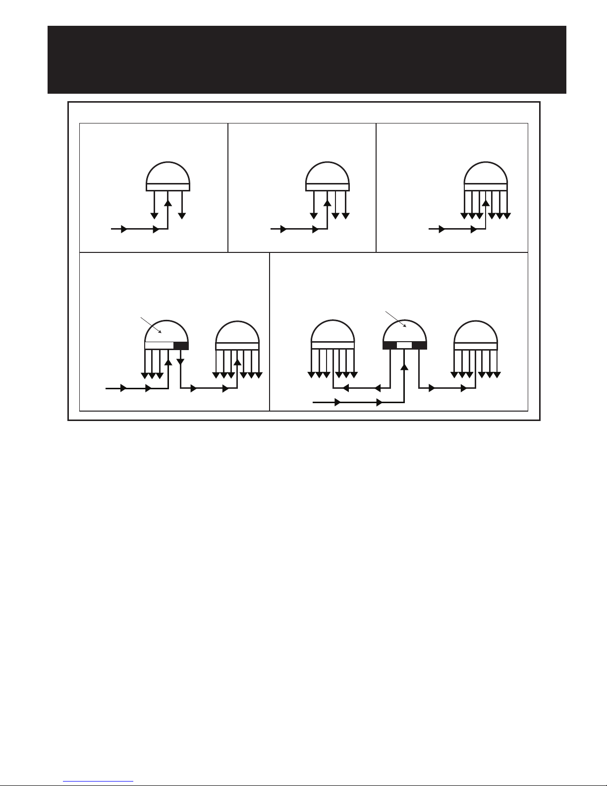
The water valve automatically distrib-
utes water to different areas of your
pool, which can include the floor, steps, benches, spa and
water features. It cycles much like an automatic sprinkler sys-
tem in your yard switching from one circuit to another (Figure
1 shows the combination of water valves). Every water valve
has a center port. This is where the water enters the valve.
You will have a 2-port, 3-port, 6-port, 9-port or 12-port system
depending on the design of your pool. The port count of the
water valve indicates the number of circuits that send water
back to your pool or to another water valve. Cleaning nozzles
or returns are placed at the end of the circuits.
WHAT IS A WATER VALVE?
5
WHAT IS A WATER VALVE? (CONT.)
Combination Water Valves (9-Port and 12-Port)
A 9-port system consists of 2 water valves, a 6-port and a 4-port. The
4-port valve has 3 circuits to the pool and 1 circuit that powers the
6 port valve for a total of 9 circuits going to the pool. On this type
of system the 3 circuits on the 4-port valve fire twice as often as the
other 6 circuits on the six port valve. Your system is designed specifi-
cally to take advantage of this firing sequence.
A 12-port system consists of 3 water valves, two 6-ports and one
2-port, 5 gear valve. The 2-port alternately powers each 6-port valve.
Your system is designed specifically to take advantage of this firing
sequence.
12 PORT VALVE
12 PORT VALVE - 2 P ORT
SPECIAL VALVE PORTED
INTER NALLY TO FEED 3
CIRCUTS THROUGH 1 PORT
9 PORT VALVE
9 PORT VALVE - 4 P ORT
SPECIAL VALVE PORTED
INTER NALLY TO FEED 3
CIRCUTS THROUGH 1 PORT
6 PORT VALVE2 PORT VALVE 3 PORT VALVE
FROM
PUMP
FROM
PUMP
FROM
PUMP
FROM
PUMP
FROM
PUMP
Figure 1

6
The run/pause switch on the top of the valve allows you to pause the
system to isolate a circuit in an out of the way area of the pool.
The one-piece replacement module design allows for easy installation.
The gauge on your water valve is important and tells you how the
system is operating. Gauges should be replaced when they become
unreadable or inaccurate. Never use Teflon tape on a replacement
gauge, use a thread sealant that is approved for plastic such as
Teflon paste. Hand tighten gauge as over tightening can crack the
water valve lid.
UNIQUE WATER VALVE FEATURES
7
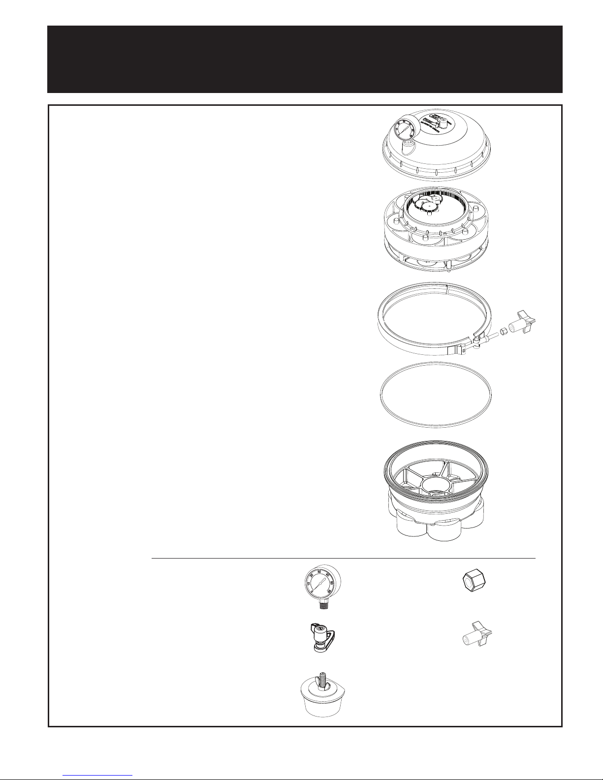
WATER VALVE BREAKDOWN
Top Dome Complete
Includes Top, Gauge & Pause Assembly:
005-302-4300-03
Modules:
004-302-4400-00 2 Port 4 Gear
004-302-4402-00 2 Port 5 Gear
004-302-4404-00 3 Port
004-302-4406-00 4 Port
004-302-4408-00 6 Port
Band Clamp Complete
Includes Knob & Nut:
005-302-3570-00
Base O-Ring:
005-302-0100-00
Valve Base (US)*:
005-302-4002-03 2 Port Base 2” Black
005-302-4012-03 3 Port Base 2” Black
005-302-4018-03 4 Port Base 2” Black
005-302-4032-03 6 Port Base 2” Black
Valve Base (US)*:
005-302-4000-03 2 Port Base 1”
1/2 Black
005-302-4010-03 3 Port Base 1”
1/2 Black
005-302-4016-03 4 Port Base 1”
1/2 Black
005-302-4030-03 6 Port Base 1”
1/2 Black
Pressure Gauge:
005-302-3590-00
Pause Assembly (Includes
Screw Knob, O-Ring & Pawl)
005-302-3502-00
Winterizing Plug:
004-302-1670-00 (Single)
004-302-1672-00 (6 Pieces)
Band Clamp Nut:
005-302-0640-00
Band Clamp Knob:
005-302-3600-00
Valve Base (Metric):
005-302-4006-03 2 Port Base 63 mm Black
005-302-4009-03 3 Port Base 63 mm Black
005-302-4020-03 4 Port Base 63 mm Black
005-302-4038-03 6 Port Base 63 mm Black
*US 2” is equivelant to Australian 50 mm.
Figure 2
NOTE: Winterizing plug is for 2 inch and
63 mm only.
For 1 ½ inch valve base use a standard #8
winterizing plug.

8
How to open the water valve
1. TURN OFF ALL EQUIPMENT INCLUDING PUMPS.
WARNING! FAILURE TO DO SO CAN RESULT IN INJURY OR
DEATH.
2. Remove the band clamp by turning the clamp knob or 7/16 inch
nut counter-clockwise until it comes off the bolt. Then carefully
pull the clamp away from the valve.
3. Lift the top off the base being careful to not lose or stretch the
o-ring.
4. Remove the module by lifting up and out of the base.
Note: the module is designed to seal inside the base so it may
require a side to side or rocking motion while lifting out. An easy
solution is to turn the pump on and off quickly. CAUTION! DO
NOT APPROACH THE WATER VALVE WHILE THE THE LID IS
REMOVED AND THE PUMP IS ON. FAILURE TO DO SO CAN
RESULT IN INJURY OR DEATH.
5. Do not pull the module by the gear mechanism. This can result in
damage to the module.
WATER VALVE INSTRUCTIONS

9
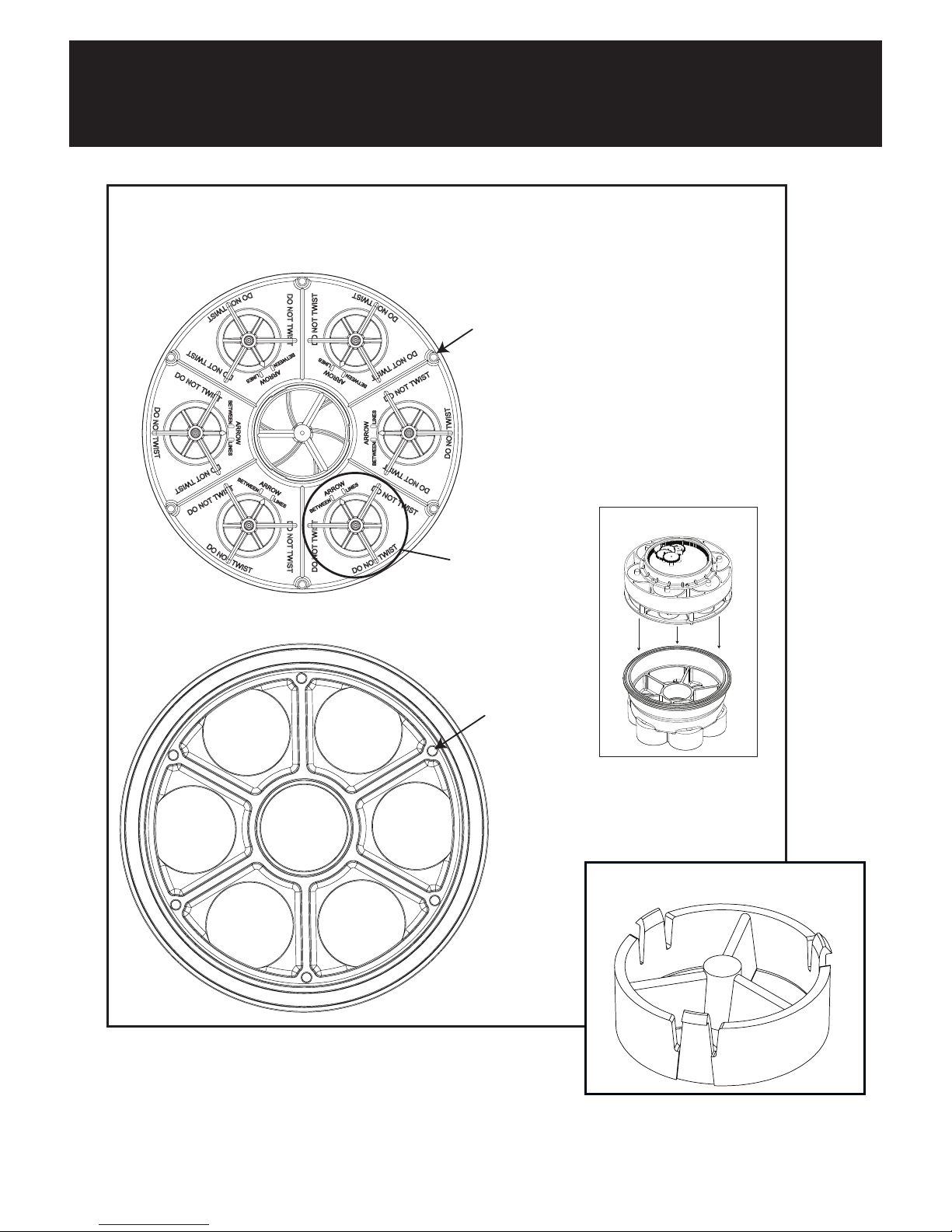
Module Installation (6-port)
1. Check the o-ring and groove for debris, and clean if necessary
(this is a quad ring and is almost square, the height is slightly big-
ger than the width).
2. Replace the o-ring (Part # 005-302-0100-00) if it is stretched or
damaged. The o-ring does not require any lubrication. Lubricating
o-ring can attract dirt and debris that could prevent it from seal-
ing. Never use petroleum jelly on plastic or rubber parts, as this
will damage them.
3. Set the module in the base and turn until the alignment pins on
the bottom of the module drop into the alignment holes in the
base (Figure 3).
4. The module should fit in the base without forcing it. If it does not
seat easily then check the following.
• (Figure 3) shows the piston portion of the current module
design (released 06-2011). These pistons are set at the
factory. Do not touch, pull or turn these pistons. Any handling
will negatively affect the performance and fit of this product.
• If the flow optimizer (Figure 4) prevents the module from
seating properly in the base you may have to remove it. To
remove optimizer press in on the 3 clips and pull to seperate.
WATER VALVE INSTRUCTIONS
(CONT.)
10
WATER VALVE INSTRUCTIONS
(CONT.)
ALIGNMENT PINS
MODULE
(BOTTOM VIEW)
BASE
(TOP VIEW)
PISTONS
ALIGNMENT HOLES
SIDE VIEW
Figure 3
Figure 4
(RELEASED 06-2011)
 Loading...