


SELECT FITNESS CIRCUIT
CHEST PRESS / VERTICAL BUTTERFLY
SF-1500
ASSEMBLY MANUAL
AM-SF-1500
Rev 10/02

S
AFETY
1. Review and understand all of the warning labels affixed to the machines and t he
facility safety sign. Replace any warning label at first sign of wear. Labels and the Facility
Safety Sign may be obtained from Paramount free of charge.
2. Be certain that machine operation is understood before machine is used . Refe r to
the instruction label provided with th e machine.
3. Keep children away from this equipment.
4. DO NOT high-pin or double-pin the weight stack. DO NOT allow the machi ne to be
used if the top plate or weight stack is pinned in a raised position. Use an assistant and
carefully return the machine to the proper position with the cap plate resting on the top
weight. Inspect the cable to ensure that it is seated in all of the pulleys.
5. Use ONLY Paramount weight selector pins. Other manufacturer’s pins may work
free of the weight stack causing possible injury. Be certain the pin is completely
inserted prior to use.
6. Cables: Inspect the entire cable and the en d fi ttin gs d ai l y. Pay close attention t o th e
area going over pulleys a nd t o th e en d co nnections. When adjustin g cab l es at thr ea de d
inserts make sure all connections are tight. Adjust tension on cables as needed.
Replace all cables at first signs of wear . Use only Paramount supplied replacement
cables. Ensure that the dimension from under the bolt head to the top surface of the
selector bar is no greater than 1-3/8 inches (see installation). Ensure that the cable tension bolt & nut are tight.
7. Nuts, Bolts, and Fasteners: Check tightness weekly. If any hardware has become
™
loose, retighten and/or use Loctite
8. Frames and Lifting Arms: Inspect weekly for integrity and function. Replace any
component at first signs of wear.
Threadlocker 242.
9. DO NOT attempt to free any jammed assemb lie s by yourse lf as this m ay cause inj ury.
10. Use ONLY Paramount adder weights or adder weight systems for incremental
resistance adjustment. NEVER use dumbbells or other means to do this.
11. Instruct Users not to wear loose or dangling clothes or have headphone wire hanging when using this equipment.
12. Recommend that users receive a medical exam before commencing an exercise
program. User should stop exercising if they feel faint or dizzy.
13. Check regularly the functionality of your machine by verifying the fol lowing:
• cables and end fittings are intact and tensioned properly,
• all adjustments are possible and carried out with ease,
• the proper selector pin is in the weight stack,
• the exercise is performed smoothly, free of noise and/or binding,
• and the guide rods and linea r bearings are properly lubricated.
14. Follow the installation guidelines provided with the products.
15. Retain these instructions for future reference.
If you have any questions, do not hesitate to contact your Paramount dealer or Para-
mount Fitness Corp. at (800)721-2121 or www.paramountfitness.com.
Refer to Maintenance Schedule label on machine for when to schedule maintenance.
1

MAINTENANCE
1. Frames: Wipe all machines down with a damp cloth and dry completely each day. This includes painted,
chrome parts and upholstered pads.
2. Painted/chrom e parts: Use Simple Green or similar cleaner for light dirt and grime. Use TurtleWax®
Polishing Compound or a good car polish to remove heavier dirt and grease as well as for polishing. DO
NOT use solvents, lacquer thinner, acetone or finger nail polish remover. For scuffs and marks that are not
removed by the above methods use a soft scrub cleanser.
3. Upholstery: Use cloth towels and warm water daily to remove surface dirt and perspiration. Use a lanolin based hand cleaner or Naugahyde® brand upholstery cleaner to condition and deep clean on a weekly
basis. DO NOT use Windex, Simple Green, 409, or similar products to clean the upholstery.
4. Weight stack enclosures (shrouds): Wipe down with a damp cloth as needed.
5. Exercise instruction labels: Clean with soap and water as needed.
6. Linear bearing shafts: Wipe down linear rails using a light application of Magnalube® lubricant or a
similar teflon grease on a weekly basis to remove dust, hair, and dirt. Polish the shaft using fine sandpaper
or steel wool if light rust is present.
7. Guide rods: Wipe all dirt and dust off the guide rods before applying a light application of Tri-Flow
TM
other silicone spray lubricant, spraying the Tri-Flow
DO NOT use oil base lubricants such as WD-40. Caution: Tri-Flow
on a rag and then wiping the guide rods with the rag.
TM
will stain carpet and clothing.
8. Bronze bushings: Check monthly for signs of wear and replace as needed. Lubricate monthly with Tri-
TM
Flow
.
9. Seat adjustments: Clean the chrome seat adjustment tube on a weekly basis using a rag sprayed with
Tri-Flow
TM
. Keep a light layer of Tri-FlowTM on these tubes at all times.
TM
or
We recommend that you purchase the Paramount Performance Kit (P/N KIT-01) to maintain your Paramount products. This will insure that the proper maintenance materials required will be used. Please refer
to the General Maintenance Manual (p/n AM-GMM) for other important safety and maintenance information.
ASSEMBLY NOTES
1) It is recommended that two (2) people be used to assemble this machine.
2) Assemble this machine on a solid level surface. Read the assembly instructions completely before
beginning to assemble the machine. This will help you to become familiar with the machine and prevent mistakes requiring unnecessary disassembly and reassembly.
3) Hardware placement is indicated as , etc. Refer to the hardware page for corresponding size and
configuration. You will have some remaining hardware as extra pieces are always included in one of
the bags.
4) Install all plastic end caps on assemblies where necessary before assembling the machine.
5) Initially tighten all hardware by hand, as this will assist in the alignment of the machine. When the
framework of the machine is complete, tighten all nuts, bolts and setscrews. Be sure all hardware is
tight before using the machine. Recheck all hardware upon completion of the assembly process.
6) Hex- and Sockethead bolt length is measured from the bottom of the head to the end of the bolt.
Length of Flathead bolts is measured as the total overall length.
A
7) Bolts should point inward on the machine wherever possible, leaving the bolt heads facing out.
8) Route cables prior to installing pulley wheels. Verify that the cables are seated in the pulleys prior to
using the equipment.
9) Read and understand all machine warning and instruction labels before using the machine.
2
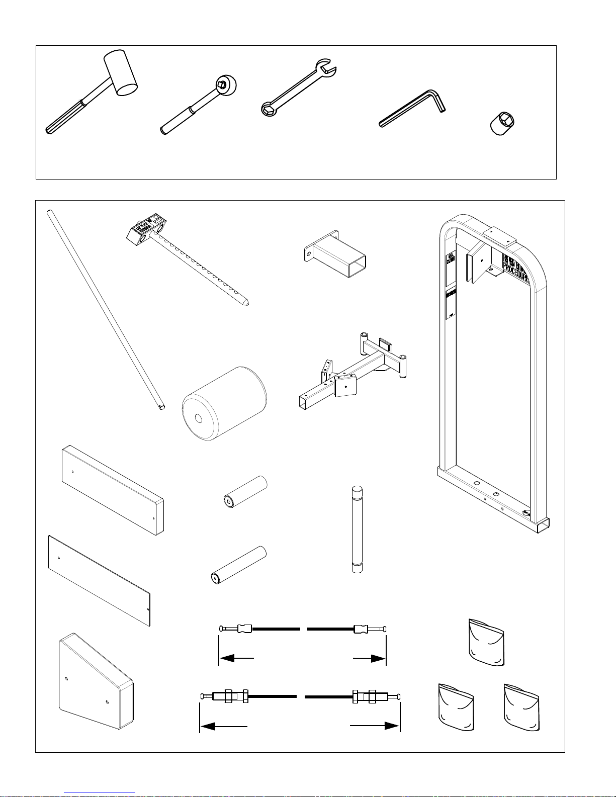
TOOLS REQUIRED:
RUBBER
MALLET
SF-1500CTN1:
SOCKET
WRENCH
9099780X
WRENCH
7/16” (11mm)
9/16” (14mm)
7/8” (22mm)
15/16” (24mm)
8093040
ALLEN WRENCH
5/32” (4mm)
7/32” (6mm)
SOCKET
7/16” (11mm)
9/16” (14mm)
9000801X (2)
8001540X
8001539
8001120X (2)
1501597X
1501596X
1501505X
1501595
144 3/4” (368cm)
1501610
1501515X
HW-1501-1
8001520X
217 3/8” (552cm)
1501615
HW-1501-2
HW-1501-3
3
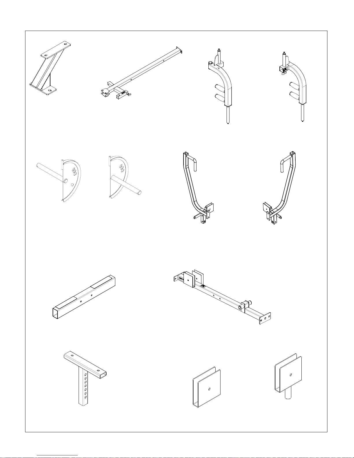
SF-1500CTN2:
1501500
1501525
1501510X
1501530
1501550X
1501555X
1501570X 1501575X
8093006X
8001525
1501520X
9098831A
4000PLY000
4

HARDWARE BAG 1501-2:
B 582 (2)
B 921 (6)
B 1182 (2)
B1117 (8)
B 682 (8)
B1136
D 829B (2)
B1015
B 447
8001594 (2)
B 900 (8)
B 898
HARDWARE BAG 1501-1:
B
3/8-16 x 1 BHCS
3/8 Black Washer
3/8-16 Locknut
3/8 Metal Base
Plastic Cover for 3/8
L
DG
3/8-16 x 2 3/4 HHCS
3/8 Black Washer (2)
3/8-16 Locknut
3/8 Metal Base (2)
Plastic Cover for 3/8 (2)
N
3/8-16 x 1 3/4 HHCS
3/8-16 Locknut
3/8 Black Washer (2)
3/8 Metal Base (2)
Plastic Cover for 3/8(2)
3/8-16 x 2 HHCS
3/8 Metal Base
3/8 Split Lockwasher
3/8 Washer
Plastic Cover for 3/8
B 1295
E
3/8-16 x 3/4 BHCS
3/8 Lock Washer
3/8 Washer
S
3/8-16 x 4 HHCS
3/8 Metal Base
3/8 Split Lockwasher
3/8 Black Washer
Plastic Cover for 3/8
8001593 (2)
F
3/8-16 x 3 HHCS
3/8-16 Thin Locknut
3/8 Metal Base (2)
3/8 Black Washer (2)
Plastic Cover for 3/8 (2)
C 754B
3/8” Black
Washer (6)
3/8-16 X 3 3/4 HHCS
3/8-16 Locknut
3/8 Black Washer (2)
3/8 Metal Base (2)
Plastic Cover for 3/8 (2)
C 757
1” USS Flat
Washer (2)
B 460
H
3/8-16 x 4 HHCS
3/8 Black Washer (2)
3/8-16 Locknut
Plastic Cover for 3/8 (2)
3/8 Metal Base (2)
C 766A
3/8-16
Locknut (4)
C 446
3/8-16 x 1 1/4
HHCS (2)
C 641
1/2-13 x 1 1/4
SHCS (2)
C 628
3/8-16 x 2 1/4
SHCS (2)
C 612
1/4-20 x 1 3/4
SHCS (2)
C 675A
1/4-20 x 5/8
BHCS (2)
C 955
Plastic Co ver for
3/8 & 1/2” (4)
C 749
3/8” Split
Lockwasher (4)
C 955A
3/8” Metal
Base (4)
C 750
1/2” Split
Lockwasher (2)
C 747
1/4” Split
Lockwasher (2)
C 740
1/4-20 Insert
Locknut (2)
5

MINIMUM FLOOR AREA REQUIRED:
59”
(150cm)
MACHINE WEIGHT (NOT INCLUDING
WEIGHT OF USER):
W/ 170LB STACK 471 LBS
W/ 250LB STACK 551 LBS
SHROUD OPTION +30LB
95”
(241cm)
IN USE
39” (99cm)
75” (191cm)
IN USE
HEIGHT= 75” (191 cm)
NOTE: THIS MACHINE IS DESIGNED FOR
USERS WEIGHING 300LB OR LESS
HARDWARE MEASUREMENT GUIDE:
BHCS - BUTTON HEAD CAP SCREW
SHCS - SOCKET HEAD CAP SCREW
MEASURE BOLT
FROM HERE
FHCS - FLAT HEAD CAP SCREW
HHCS - HEX HEAD CAP SCREW
12345
6

1
8093040
H (2)
2
G (4)
1501500
E (2)
1501515X
NOTE: ST ABILIZER FOOT MUST BE
ATTACHED TO THE MACHINE!
8093006X
1501520X
D (2)
TOP VIEW
PULLEY HOUSING
1501515X
1501505X
NOTE: WHEN INSTALLING HARDWARE,
TIGHTEN BY HAND ONLY UNTIL ALL
COMPONENTS ARE ASSEMBLED. BOLT
HEADS SHOULD FACE TO OUTSIDE OF
MACHINE WHERE POSSIBLE. BE SURE
ALL HARDWARE IS TIGHT BEFORE
1501510X
F (2)
7

3
5
C 641
C 750
1501595
1501570X
150157
1501596X
C 675A
C 747
C 955 (2)
C 446 (2)
C 749 (2)
C 955A (2)
C 754B (2)
4
1501555X
1501525
1501530
1501550X
C 612
C 740
D 829B
8

5
8001594 (2)
6
8001593
C 955
C 955A
C 766A
C 754B
8001120X (2)
8001540X
8001539
S (2)
B1295 (2)
8001520X
8001525
N (2)
9

WEIGHT STACK INSTALLATION
Review the equipment order to determine
the weight stack configuration. The
boxes are marked with the quantity and
weight of the plates.
P/N: B1602
Comprised of
(4) EACH 10lb MACHINED WEIGHT PLATES
or
P/N: B1603
Comprised of
(4) EACH 15lb MACHINED WEIGHT PLATES
170lb
16 x 10lb plates
Qty (4) Box B1602
7
250lb
16 x 15lb plates
Qty (4) Box B1603
NOTE: TIGHTEN
HARDWARE BY HAND
ONLY AT THIS POINT.
FRONT VIEW
B (2)
B 447
9000801X (2)
9099780X
WEIGHT
PLATES
C 757 (2)
B 582 (2)
NOTE: IF INSTALLING THE WEIGHT SHROUD
OPTION REFER TO THE INSTALLATION
INSTRUCTIONS PROVIDED WITH THE OPTION.
10

8
9099780X
NOTE: MOVE CAP PLATE 9099780X UP TO PULLEY HOUSING
TO SET THE CORRECT GUIDE ROD AND BRACKET SPACING.
NOW COMPLETELY TIGHTEN HARDWARE. CAP PLATE
SHOULD MOVE SMOO TH LY ALONG GUIDE RODS. IF NOT,
LOOSEN HARDWARE AND RESET SPACING.
9
L (2)
1501610
C 766A (2)
B 900 (3)
4000PLY000
L
11

10
B 898
L
1501615
MAX!
1 3/8” (35mm)
1501615
MAKE SURE
LOCKING NUT
IS SECURE!
11
9098831A
G
B 460
NOTE: PARAMOUNT SELECTOR PIN B 460 IS
THE ONLY PIN THAT SHOULD BE USED WITH
THIS MACHINE. UNDER NO CIRCUMST ANCES
SHOULD THE CAP PLATE OR WEIGHT STACK
BE PINNED IN AN ELEVATED POSITION.
1501597X
B 900 (5)
L (2)
1501615
C 628 (2)
C 749 (2)
C 754B (2)
12

SELECT FITNESS
W
EIGHT STACK LABEL INSTALLATION
Hardware Bag 1501-3 is packed with a weight stack number label set. Follow th e i nstructions printed on the label. Be low is a list of weight stacks an d t he corresp ond ing lab el se t
part numbers:
To install weight stack labels:
1. Verify weights are installed properly.
2. Wipe front surface of the weights with rubbing alcohol and a llow to dry completely.
3. Remove the backing from the labels. Align the top edge of the label with the top
edge of the weights and the side of the label with the outside edge of the pin hole in
the weights.
F
ITNESS LINE
WEIGHT ST ACK LABELS
WEIGHT ST ACK LABELS
Wt. Stack 170lb 250lb
Part No. B2170 B2172
4. Verify that the label strip is straight and then remove the liner. As the liner comes off
the labels, press and rub each la be l in to place.
5. The adhesive requires 48 hours to cure so DO NOT attempt to “test” the integrity of
the labels after they have been installed.
Take the time during inst allatio n to align the la bel with th e edge of the pin ho le and the top
surface of the weights to get all of the individual labels straight.
Liner
Individual
labels
Align with outside
edge of pin holes
13

W ARNING LABELS
The following warning labels are affixed to the SF-1500. Be certain that you and the
facility staff are aware of the meaning and importance of each label. If the labels become
damaged, replacements can be or dered free of charge from Paramou nt.
!
WARNING
SERIOUS INJURY CAN OCCUR. KEEP YOUR HANDS
CLEAR OF THIS AREA DURING USE OF THE MACHINE.
P/N B2316 6/96
ASTM Fxxx
B2316
!
WARNING
SERIOUS INJURY CAN OCCUR ON THIS EQUIPMENT IF
THE PIN IS NOT COMPLETELY INSERTED BEFORE USE.
P/N B2065 11/96
ASTM Fxxx
B2065
!
WARNING
STABILIZING FOOT MUST BE ATTACHED HERE.
P/N B2017
ASTM Fxxx
B2017
!
WARNING
SERIOUS INJURY CAN OCCUR
ON THIS EQUIPMENT IF THE
CABLES AND THEIR ATTACHMENT COMPONENTS ARE NOT
INSPECTED OFTEN. REPLACE
AT FIRST SIGNS OF WEAR.
P/N B2051 6/96
ASTM Fxxx
B2051
!
WARNING
1. MAKE SURE selector pin is inserted
completely. Use only the Paramount pin shown
2. Bolt height must not exceed 1 3/8”. Check
regularly. Make sure locking nut is tight.
ASTM F1749
MAINTENANCE
SCHEDULE
Check the integrity and function
of the following items. Replace
all worn components immediately.
Cables - Check tension, end
Upholstery - Wipe down and dry
Frame - Wipe down and dry
Chrome - Wipe down and dry
Nuts/Bolts/Fasteners - Tighten
Guide Rods - Lubricate and clean
Linear Rods - Lubricate and clean
Seat Sleeves- Lubricate and clean
Adjustments/Locking Pins/
Weight Stack Pin
Warning/Instruction Labels
Springs
Anti-Skid
Hand Grips
Order Paramount Serv ice Kit P/N KIT-01
for recommended maintenance products
PARAMOUNT CUST OMER SERVICE
P/N B2141
fittings, and coating
Check weight stack
locking nut
Clean and condition
Polish/Wax
Polish/Wax
and/or adjust as needed
Tightening Knobs
1-800-721-2121
PIN
B2315
MAXIMUM Heig ht
under Nut to
Bolt head
e
H
”
5
Paramount Pin P/n B 460
P/N B2315 5/98
o
t
d
a
MAX
1 3/8”
B
W
D
E
A
E
I
K
L
L
Y
Y
4
4
4
4
4
4
4
4
4
4
4
4
4
4
4
4
4
4
l
l
a
!
WARNING
SERIOUS INJURY CAN OCCUR ON
THIS EQUIPMENT. FOLLOW THESE
PRECAUTIONS TO HELP AVOID INJURY.
1. BEFORE USING: Read all of the
warnings and obtain instruction on
the use of this machine. Use only for
the intended exercise. DO NOT
modify the machine.
2. Get a medical exam before
beginning an exercise program.
3. Keep body and clothing clear of all
moving parts. DO NOT wear anything
loose or dangling.
4. Inspect the machine before use.
DO NOT use it if it appears damaged.
DO NOT try to fix any machine.
Notify staff immediately.
5. INSPECT MACHINE DAILY for
loose, worn or damaged parts.
Tighten and adjust all loose parts.
Replace any part or label at first
signs of wear. Inspect all cables and
their connections closely. If you are
in doubt about any part, DO NOT
use the machine until the part is
replaced.
6. Inspect cables and connections
before using the machine. DO NOT
use this machine if any part appears
worn or damaged.
7. Be certain that weight pin B1003 is
completely inserted. Use only the pin
provided by the manufacturer. If
unsure, seek assistance.
8. NEVER pin the weights or top plate
into an elevated position. DO NOT
use the machine if found in this
condition. DO NOT try to fix. Se e k
assistance.
9. Use only the incremental weights
supplied by the manufacturer. DO
NOT use dumbbells or other means
to add resistance to the machine.
10. NEVER allow children near this
machine. Supervise teenagers.
11. DO NOT REMOVE THIS LABEL.
REPLACE IF DAMAGED.
P/N B2060 1/98
ASTM F1749
B2060
B2141
14

PARAMOUNT’s Limited Warranty
Paramount warran ts t o th e orig ina l purch aser from a Par amount au thorize d dea ler that P aramount equipment will be free from defects in material and workmanship under normal use and
service for the following periods and in the following respects:
LIFETIME WARRANTY Welds, Weight Plates, and Guide Rods
FIVE YEAR WARRANTY Bronze Bushings, Sealed Rotating Bearings and Pulley Wheels
ONE YEAR WARRANTY Cables, Linear Bearings, Linear Shafts and all other components
not mentioned elsewhere in this warranty
90-DAY WARRANTY Upholstery and Grips
This limited warranty DOES NOT cover and no warranty is given with respect to:
‚ Products not manufac tured by Paramount
‚ Products which are altered without the express written consent of Paramount
‚ Products purchased other than directly from Paramount or through a Paramount autho-
rized dealer.
All warranty periods begin to run from the date of delivery to the original purchaser. The
obligation of Paramount under this warranty is limited to repairing or replacing warranted defective parts, as Paramount may elect, at Paramount’s plant in Los Angeles, California, without
charge to purchaser for either parts or labor. Purchaser is responsible for all transportation and
insurance costs of retur ned or replace d equipmen t to and from Para mount’ s plant i n Los Angeles.
ANY IMPLIED WARRANTY, INCLUDING BUT NOT LIMITED TO THE IMPLIED WARRANTY OF FITNESS FOR A PARTICULAR PURPOSE AND THE IMPLIED WARRANTY OF
MERCHANTABILITY, IS LIMITED TO THE ONE YEAR DURATION FROM THE DATE OF
DELIVERY TO THE ORIGINAL PURCHASER. SOME ST ATES DO NOT ALLOW LIMITATIONS
ON HOW LONG AN IMPLIED WA RRANTY LASTS, SO THE ABOVE LIMITATION MAY NOT
APPLY TO YOU. THE REMEDY OF REPAIR AND REPLACEMENT IS THE EXCLUSIVE AND
SOLE REMEDY OF THE PUCHASER. PARAMOUNT SHALL NOT BE LIABLE FOR ANY SPECIAL, INCIDENTAL, CONTINGENT OR CONSEQUENTIAL DAMAGES OF ANY KIND,
INCLUDING, BUT NOT LIMITED TO, DAMAGE OR LOSS OF OTHER PROPERTY OR EQUIPMENT AND LOST PROFITS OR REVENUE. SOME STATES DO NOT ALLOW THE EXCLUSION OR LIMITATION OF INCIDENTAL OR CONSEQUENTIAL DAMAGES SO THE ABOVE
LIMITATION OR EXCLUSION MAY NOT APPLY TO YOU.
No action for breach of this written limited warranty or any implied warranty shall be commenced more than one year after the accrual of the cause of action. This written limited warranty
is the complete, final and exclusive agreement of the parties with respect to the quality or performance of the goods and any and all warranties and representations. No modification of this limited warranty or waiver of its terms shall be bin ding on either party unless approved in writing by
an authorized corporate officer of Paramount. This limited warranty g ives you specific legal
rights, and you may also have other righ ts which vary from st ate to stat e. Cont act Pa ramou nt Fitness Corp., 6450 E. Bandini Blvd., Los Angeles, California 90040-3185, before returning any
defective equipment. Paramount Fitness Corp. © 1999.
Paramount Fitness Corp. © 1993, 1995, 1997
For More Information On Other Paramount Products:
6450 E. Bandini Blvd., Los Angeles, CA 90040-3185 USA
Advanced Performance Products
Select Fitness Circuit
Performance Free Weight Benches
Multi-Station Machines
Call (323) 721- 2121 • (800) 721- 2121
PARAM OUNT FITNESS CORP.
 Loading...