


The Paramount Robotic Telescope System
User Guide
Paramount ME II, MYT, MX, and MX+ models
Revision 1.94 August, 2015
Copyright 2015 Software Bisque, Inc. All rights reserved.

Paramount User Guide
Information in this document is subject to change without notice and does not represent a commitment
on the part of Software Bisque. The software products described in this document are furnished under a
license agreement or nondisclosure agreement. They may be used or copied only in accordance with the
terms of the agreement. It is against the law to copy the software on any medium except as specifically
allowed in the license or nondisclosure agreement. The purchaser may make one copy of the software
for backup purposes.
No part of this manual and/or databases may be reproduced or transmitted in any form or by any means,
electronic or mechanical, including (but not limited to) photocopying, recording, or information storage
and retrieval systems, for any purpose other than the purchaser's personal use, without the express
written permission of Software Bisque, Inc.
Software Bisque
862 Brickyard Circle
Golden, CO 80403-8058
USA
Web Site: http://www.bisque.com
The Paramount ME, Paramount ME II, Paramount MX, Paramount MX+, Paramount MYT, Bisque TCS, MKS
4000, MKS 5000, and TheSkyX Professional Edition Astronomy Software are trademarks of Software
Bisque, Inc.
All other product names are trademarks of their respective owners and are used solely for identification.
2 | P a g e

Paramount User Guide
Table of Contents
Telescope Operation Disclaimer ................................................................................................................... 8
Sun Warning .................................................................................................................................................. 8
The Paramount Robotic Telescope System .................................................................................................. 9
Paramount Model Comparison ............................................................................................................... 12
Optional Accessories ............................................................................................................................... 14
Getting Help ................................................................................................................................................ 15
What You Need to Know ............................................................................................................................. 15
Coordinate Systems ................................................................................................................................ 16
The Horizon Coordinate System ......................................................................................................... 16
The Equatorial Coordinate System ..................................................................................................... 17
Hour Angle .......................................................................................................................................... 18
Local Sidereal Time ................................................................................................................................. 19
Atmospheric Refraction .......................................................................................................................... 19
Polar Alignment Basics ............................................................................................................................ 20
Homing .................................................................................................................................................... 22
Labeling the Home Position on the Sky Chart ..................................................................................... 23
Physically Marking the Home Position ................................................................................................ 24
Synchronization ...................................................................................................................................... 25
Best Synchronization Practices ........................................................................................................... 26
Step by Step Synchronization ............................................................................................................. 26
Session to Session Pointing Repeatability ........................................................................................... 27
Making Sure Synchronization Is Correct ............................................................................................. 28
The Local Celestial Meridian ............................................................................................................... 29
Maintaining Accurate Time ................................................................................................................. 30
Parking the Paramount ........................................................................................................................... 31
Parking from TheSkyX Professional Edition ........................................................................................ 31
Defining the Park Position ................................................................................................................... 32
Park Position Rules .............................................................................................................................. 32
Audible Control System Feedback ...................................................................................................... 32
Visual Control System Feedback ......................................................................................................... 35
3 | P a g e

Paramount User Guide
Through the Mount Cabling ................................................................................................................ 35
Packing List .................................................................................................................................................. 41
Box 1 Contents ........................................................................................................................................ 41
Important Packing Material Notes ...................................................................................................... 43
Box 2 Contents (Accessories Box) ........................................................................................................... 44
Locating Your Serial Numbers ............................................................................................................. 47
Paramount and Software Serial Number Registration ........................................................................... 48
Unpacking the Paramount .......................................................................................................................... 48
Your Safety is Paramount ........................................................................................................................ 48
Paramount ME II Unpacking Insert ..................................................................................................... 49
Paramount MX Unpacking Insert ........................................................................................................ 50
Paramount MX+ Unpacking Insert ...................................................................................................... 51
Paramount MYT Unpacking Insert ...................................................................................................... 52
Packing the Paramount for Transport .................................................................................................... 54
Paramount Components ............................................................................................................................. 55
Paramount ME II Front View ................................................................................................................... 56
Paramount MX Front View ..................................................................................................................... 57
Paramount MX+ Front View ................................................................................................................... 58
Paramount MYT Front View .................................................................................................................... 59
RA Worm Block Cover ......................................................................................................................... 59
Payload Mounting Plate (Versa-Plate) ................................................................................................ 60
Paramount Versa-Plate Knobs ............................................................................................................ 63
Large Dovetail Accessory Rail (Paramount ME II only, Optional) ....................................................... 68
Instrument Panel ................................................................................................................................. 68
RA Worm Block Cover ......................................................................................................................... 72
RA Cable Conduit ................................................................................................................................ 72
RA Gear Cover (ME II Only) ................................................................................................................. 72
Dec Cable Conduit ............................................................................................................................... 72
Right Ascension Carrying Handle ........................................................................................................ 72
RA Worm Block Switch ........................................................................................................................ 73
RA Spring Plunger and Cam Stop Access Hole (Paramount ME II and MX+ Only) .............................. 77
RA Encoder Cover (Paramount ME II Only) ......................................................................................... 77
4 | P a g e

Paramount User Guide
RA Assembly ........................................................................................................................................ 77
Electronics Box .................................................................................................................................... 77
Polar Axis Adjustments ....................................................................................................................... 81
Azimuth Adjuster Knobs ......................................................................................................................... 82
Base Thrust Mounting Knobs .............................................................................................................. 84
Base Plate ............................................................................................................................................ 84
Paramount ME II Rear View .................................................................................................................... 85
Paramount MX Rear View ....................................................................................................................... 86
Paramount MX+ Rear View ..................................................................................................................... 87
Declination Carrying Handle (Paramount MX Only) ........................................................................... 88
Declination Axis Three Position Switch (Paramount MX Dec Three Position Switch) ........................ 88
Cable Conduit Access Hole and Cover ................................................................................................ 88
Right Ascension Axis Locking Hole (Paramount ME II Only) ............................................................... 89
Configurable Hard Stop Positions (Paramount ME II Only) ................................................................ 90
Declination Axis Assembly (Dec Assembly) ......................................................................................... 90
Paramount Serial Number (Serial Number) ........................................................................................ 91
Altitude Scale ...................................................................................................................................... 91
Altitude Adjuster ................................................................................................................................. 93
Counterweight Shaft ........................................................................................................................... 98
Counterweight Shaft Extension Bar (Optional) ................................................................................... 99
Counterweights ................................................................................................................................... 99
Payload Imbalance Cause and Effect ................................................................................................ 101
Balancing the Payload ....................................................................................................................... 101
Counterweight Safety Knob .............................................................................................................. 102
Paramount ME II Side View ................................................................................................................... 103
Paramount MX Side View ..................................................................................................................... 104
Paramount MX+ Side View ................................................................................................................... 105
Altitude Adjuster Thrust Knobs ......................................................................................................... 106
Wedge ............................................................................................................................................... 106
Bubble Level ...................................................................................................................................... 107
Declination Axis Locking Hole (Paramount ME II Only) .................................................................... 108
Micro Levelers (Paramount ME II Only) ............................................................................................ 108
5 | P a g e

Paramount User Guide
Hand Controller ................................................................................................................................. 110
Other Paramount Accessories .............................................................................................................. 111
USB 2.0 Cable .................................................................................................................................... 111
Hex Wrenches ................................................................................................................................... 112
Power Supply Unit (PSU) ................................................................................................................... 112
Altitude Adjuster Wrench (Paramount ME II Only) .......................................................................... 112
How To Polar Align .................................................................................................................................... 112
Rough Polar Alignment Method ........................................................................................................... 113
Step-By-Step Rough Polar Alignment ............................................................................................... 113
Accurate Polar Alignment ..................................................................................................................... 114
Using TheSkyX Pro for Precise Polar Alignment ................................................................................ 114
Using the Polar Alignment Scope ...................................................................................................... 115
The Paramount and TheSkyX Professional Edition ................................................................................... 116
Paramount Minimum System Requirements ....................................................................................... 116
First Time Paramount Setup ................................................................................................................. 117
Paramount USB Driver Installation ....................................................................................................... 117
Mac OS X ........................................................................................................................................... 118
Windows ........................................................................................................................................... 118
Controlling the Paramount with TheSkyX Professional Edition ............................................................ 118
Getting Started with TheSkyX Professional Edition .............................................................................. 119
The Bisque TCS Window ....................................................................................................................... 120
Status Messages (Status Text) .......................................................................................................... 121
Firmware Version and Mount Identifier ........................................................................................... 121
Parameters Tab ..................................................................................................................................... 121
Advanced Parameters ....................................................................................................................... 124
Commands Pop-up Menu ................................................................................................................. 131
Show Status Tab .................................................................................................................................... 135
Periodic Error Correction Tab ............................................................................................................... 137
Bisque TCS PEC Table Tab ................................................................................................................. 138
Compute PEC Curve Tab ................................................................................................................... 140
Collecting and Using Periodic Error Tracking Data ............................................................................... 142
Utilities Tab ....................................................................................................................................... 148
6 | P a g e

Paramount User Guide
Logging Tab ....................................................................................................................................... 164
Using ProTrack™ ....................................................................................................................................... 164
ProTrack Minimum Requirements .................................................................................................... 164
Getting Started with ProTrack .......................................................................................................... 165
Troubleshooting Mount Operation........................................................................................................... 166
USB Hubs and USB Extenders ............................................................................................................... 167
Controlling Multiple USB Devices with USB Hubs ............................................................................. 167
Windows and USB Port Power Settings ............................................................................................ 168
Appendix A: Installing the MKS 5000 USB Windows Driver ..................................................................... 170
Windows USB Driver Installation and Use ............................................................................................ 170
Accessing Windows Device Manager ................................................................................................ 171
Uninstalling the MKS 5000 Driver ..................................................................................................... 172
Appendix B: Paramount Technical Drawings ............................................................................................ 174
Computing Dome Offset Distance ........................................................................................................ 175
Appendix C: External Power Cable Sets .................................................................................................... 178
Apogee/QSI/SBIG ST-402/STF-8300 Model Camera External Power Cable Set Specifications ............ 178
SBIG ST-7 Series (5-Pin) External Power Cable Set Specifications ........................................................ 181
SBIG ST-L Series (6-Pin) External Power Cable Specs ............................................................................ 182
Finger Lakes Instruments External Cable Specs .................................................................................... 184
Generic External Power Cable Specs .................................................................................................... 185
Appendix D: Paramount Warranty ........................................................................................................... 187
MKS 5000 Warranty Replacement Procedure and Policy ..................................................................... 187
MKS 5000 Non-Warranty Replacement Procedure and Policy ............................................................. 188
Shipping Address ................................................................................................................................... 188
Appendix E: Revision History .................................................................................................................... 189
Index.......................................................................................................................................................... 192
7 | P a g e
Paramount User Guide
NEVER attempt to observe the Sun through your telescope! Without
a specially designed solar filter, viewing the Sun – for even a fraction of
a second – will cause instant, irreversible eye damage. When observing
during the day, do not point the telescope near the Sun. Do not use
TheSkyX Professional Edition’s automatic slew feature to find objects
during the day.
Telescope Operation Disclaimer
Robotic telescope mounts do not have an unlimited range of movement. The telescope’s shape, the way
it is mounted, or the addition of accessories can prevent it from pointing at particular parts of the sky. If
the telescope is forced past these points, the telescope, its mounting, or accessories might be damaged.
TheSkyX Professional Edition includes telescope limit features that let you define these inaccessible
positions; TheSkyX Professional Edition, or the mount’s control system, will try to prevent the telescope
from entering or crossing them. This feature is provided as a convenience, not as a panacea. Since any
telescope can run into its mechanical limits through accident, carelessness, or component failure,
Software Bisque cannot be responsible for any damage to your telescope that occurs when using TheSkyX
Professional Edition to control it.
Furthermore, Software Bisque cannot be held responsible for damage caused by plugging cables into
electronic devices. We strongly recommend turning off all electronic devices (computers, mobile devices,
telescopes, focusers, dew heaters, CCD cameras, etc.) before attaching any cabling or power supplies.
Sun Warning
8 | P a g e
Paramount User Guide
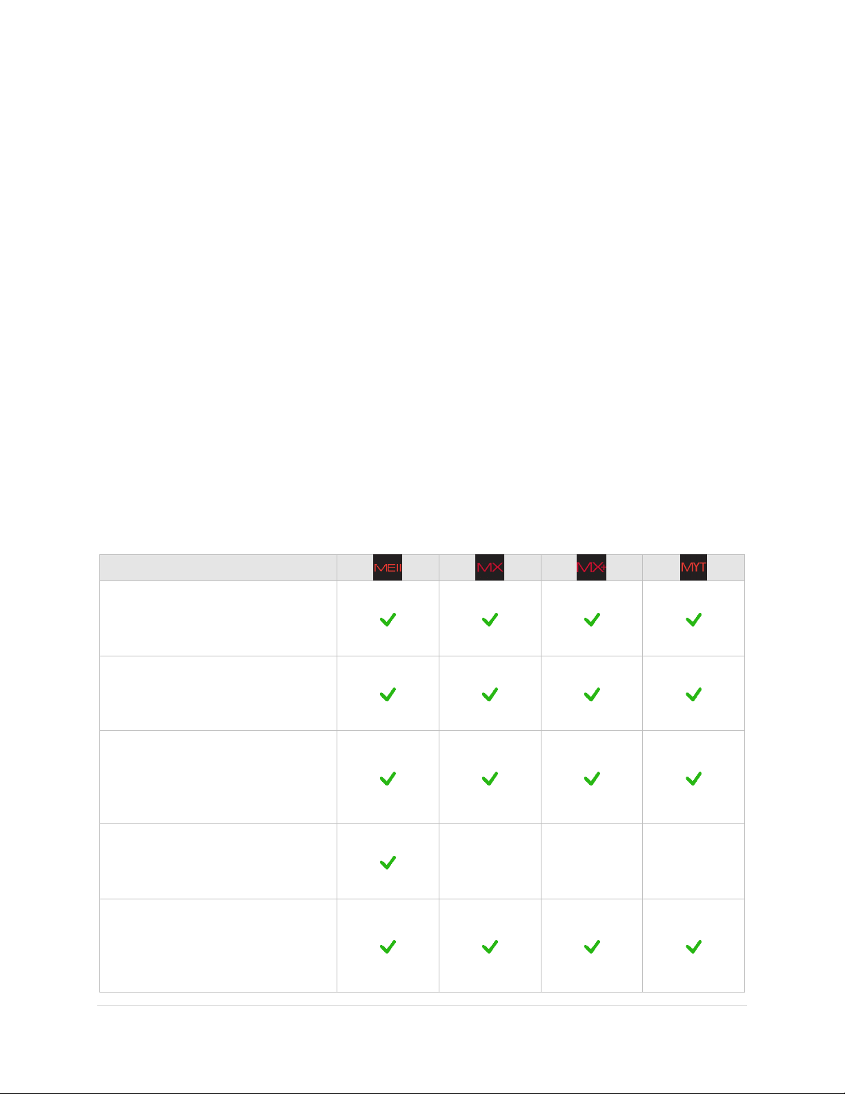
Feature
Software Bisque’s fourth
generation dual axis control system
(MKS 5000™) provides precision,
reliable performance.
Integration with TheSkyX
Professional Edition for Mac or
Windows control.
Camera Add On™ software provides
single software telescope, camera,
focuser, filter wheel, SBIG AO and
rotator control.
Dome Add On™ keeps the
motorized dome aligned with
telescope.
- - -
TPoint Add On™ with Super
Model™ and ProTrack™ provides
the same telescope pointing
correction software that is used on
most professional telescopes.
The Paramount Robotic Telescope System
Thank you for purchasing the Paramount Robotic Telescope System. The Paramount mount is an ultraprecision German equatorial mount (GEM) that is designed to deliver unmatched pointing, tracking and
stability for amateur or professional astronomers in portable or permanent installations. These precision
mechanics, when commanded TheSkyX Professional Edition, create a formidable imaging system that can
help you achieve your most lofty observing goals.
This user guide covers the basic setup and use of the Paramount ME II, Paramount MX, Paramount MX+,
and Paramount MYT model mounts, as well as how to control your mount using TheSkyX Professional
Edition.
This document assumes you are familiar with many fundamental concepts in astronomy and are
somewhat experienced using a telescope and or CCD camera in conjunction with a personal computer.
If a concept presented here is new to you, consider searching the Internet to find out more information
about it. Unfortunately, there is simply no way that all the different facets of setting up and controlling a
robotic telescope mount can be covered in a single document.
The table below lists the significant Paramount hardware, electronics and software features that are
designed to help foster memorable and productive observing experiences.
9 | P a g e
Paramount User Guide
The Multi-OS and Six License Add
On lets you install TheSkyX
Professional Edition and related
Add Ons on up to six (6) different
Mac and Windows computers.
Research-grade right ascension
gears with seven (7) arcsecond or
less peak to peak periodic error
before training PEC.
Optimal periodic error correction
curve fitting that can produce
“seeing indifferent” periodic error
curves.
Direct Guide™ allows optimal
guiding without a guider cable.
Both the right ascension and
declination axes include mechanical
switches to change quickly switch
between balancing the payload and
tracking.
The Paramount ME II’s axes
may be locked in place by
installing locking bolts
(page 89).
The Paramount MX
includes a three position
mechanical switch (page
50).
Each axis of the Paramount
MX+ and Paramount MYT
has two separate
mechanical switches (page
52).
Clutch-free worm block design
preserves the mount’s physical
orientation for accurate and
repeatable TPoint modeled
pointing and tracking.
10 | P a g e
Paramount User Guide
The control system supports a wide
dynamic range for slewing and
tracking rates. Virtually any slew
speed is available between zero
and several degrees per second.
Configurable acceleration and
deceleration rates during slews.
Integrated homing sensors that
allow rapid mount initialization to
produce precision and reliable
repeatability from night to night, or
if power is lost.
Super-stable physical design that
rapidly dampens external
vibrations.
Configurable software slewing
limits prevent damage to the
mount and telescope by slowly
decelerating to limit regions.
Clutch-free design ensures
consistent pointing and tracking
from night to night.
Fifty individual through the mount
cabling conductors that help
minimize the tedium of having CCD
power, CCD signal, focus, video,
dew heater, and other accessory
cables routed to the telescope.
Integrated Cable Conduit™ allows
adding custom cables, wires
through the mount.
Integrated rotating base allows
calibrated azimuth adjustments to
be made without affecting the
mount’s altitude.
Integrated altitude scale to provide
an accurate altitude starting point
for polar alignment.
11 | P a g e
Paramount User Guide
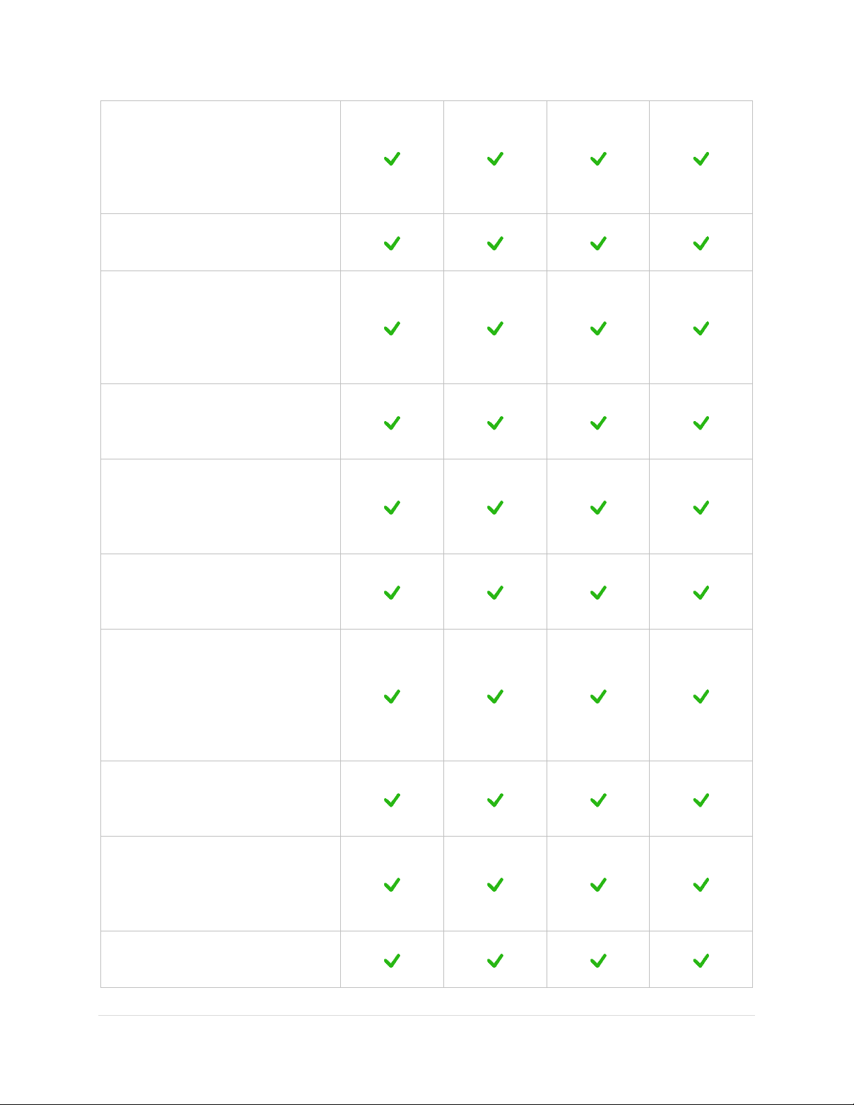
Feature or
Specification
Maximum payload
capacity (total
instrument
capacity not
including
counterweights)
109 kg/240 lb.
41 kg/90 lb.
45 kg/100 lb.
23 kg/50 lb.
Physical
dimensions
See technical
drawing
references on
page 174.
See technical
drawing
references on
page 174.
See technical
drawing
references on
page 174.
See technical
drawing
references on
page 174.
Structural design is extremely rigid,
even at maximum payload capacity.
Landing lights under the mount can
be turned on to illuminate dark
working areas during setup.
Two counterweights and one
counterweight shaft included
standard.
Oversized right ascension and
declination bearings provide
maximum stability.
20.3 cm
(8 in.)
15.2 cm
(6 in.)
15.2 cm
(6 in.)
11 cm
(4.3 in.)
Integrated equatorial wedge for
polar axis altitude adjustment.
14° – 68°
10° – 65°
10° – 65°
0° – 64°
High total instrument capacity to
mount weight ratio.
109 kg/38 kg
(240 lb./84
lb.)
41 kg/23 kg
(90 lb./50 lb.)
45 kg/23 kg
(100 lb./50
lb.)
23 kg/15.4 kg
(50 lb./34 lb.)
Power supply included with mount.
200W max
80W max
80W max
80W max
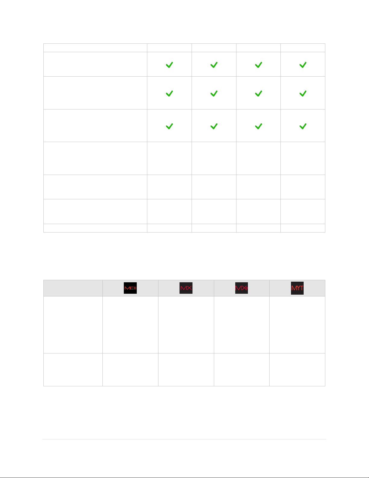
Paramount Model Comparison
The Paramount ME II, Paramount MX and Paramount MX+ are very similar in function and design. The
table below lists the “significant” differences between these models.
12 | P a g e
Paramount User Guide
Feature or
Specification
Versa-Plate
dimensions and
optional mounting
accessories (page
60)
25 cm x 51 cm x
2.5 cm
(9.9-in. x 20-in. x
1.0-in)
Four dovetail
mounting
knobs.
Optional
mounting
rails for
attaching
large OTAs.
16 cm x 41 cm x
1.8 cm
(6.4-in. x 16-in x
0.72 in.)
Three
dovetail
mounting
knobs.
16 cm x 41 cm x
1.8 cm
(6.4-in. x 16-in x
0.72 in.)
Three
dovetail
mounting
knobs.
15 cm x 35.6 cm x
1.6 cm
(5.95-in. x 14-in x
0.63 in.)
Three
dovetail
mounting
knobs.
Number of Altitude
Adjuster Thrust
Knobs (page 106)
Four (4)
Two (2)
Two (2)
Two (2)
Routing custom
cabling through
the mount
See “Through the
Mount Cabling”
on page 35 for
details.
See “Through the
Mount Cabling”
on page 35 for
details.
See “Through the
Mount Cabling”
on page 35 for
details.
See “Through the
Mount Cabling”
on page 35 for
details.
Mechanical switch
on right ascension
and declination
axes (page 73)
The Two Position
Switch engages
the worm with
the gear, or
permits payload
balance by
separating the
worm from the
gear.
The right
ascension and
declination axes
can be locked in
place for
transport, or
when adding
payload, by
installing two
locking bolts on
each axis.
The Three
Position Switch
engages the
worm with the
gear, permits
payload balance
by separating the
worm from the
gear, or locks the
gears to prevent
axis rotation
during shipment
or transport.
The Two Position
Switch engages
the worm with
the gear, or
permits payload
balance by
separating the
worm from the
gear.
The
Transportation
Lock Knob can be
placed in a lock or
balance position
for transportation
or adding payload
by pulling and
rotating a
mechanical
switch 90 degrees
for each axis.
13 | P a g e
Paramount User Guide
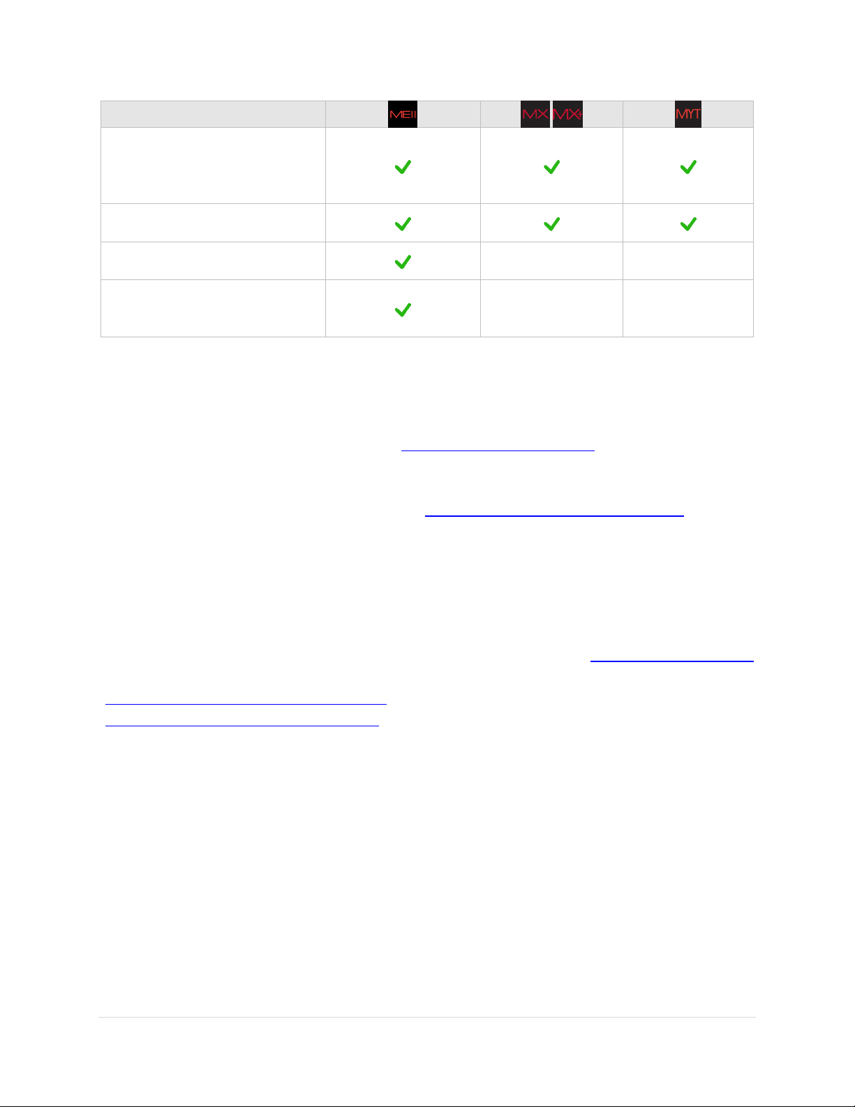
Feature or
Specification
Physical hard stops
that permit
tracking past the
meridian without
the optical tube
assembly flipping
sides
Configurable.
Five different
positions, located
at a minimum of
seven minutes to
up to two (2)
hours past the
meridian.
Fixed, nonconfigurable hard
stop position that
allows a
maximum of two
(2) hours tracking
past the
meridian.
Fixed, nonconfigurable hard
stop position that
allows a
maximum of two
(2) hours tracking
past the
meridian.
Fixed, nonconfigurable hard
stop position that
allows a
maximum of two
(2) hours tracking
past the
meridian.
Base Plate Micro
Levelers
See “Micro
Levelers
(Paramount ME II
Only)” on page
108.
Not available.
Not available.
Not available.
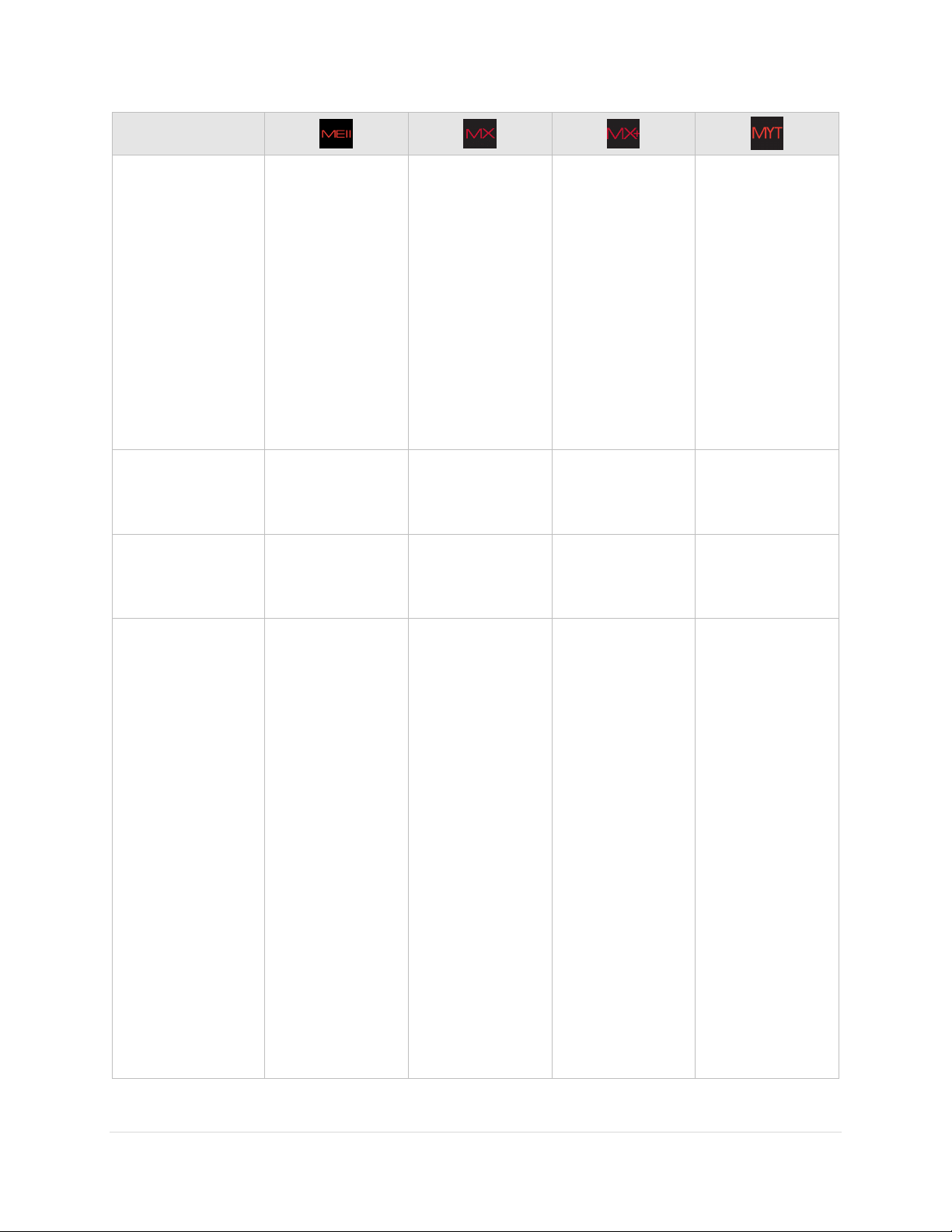
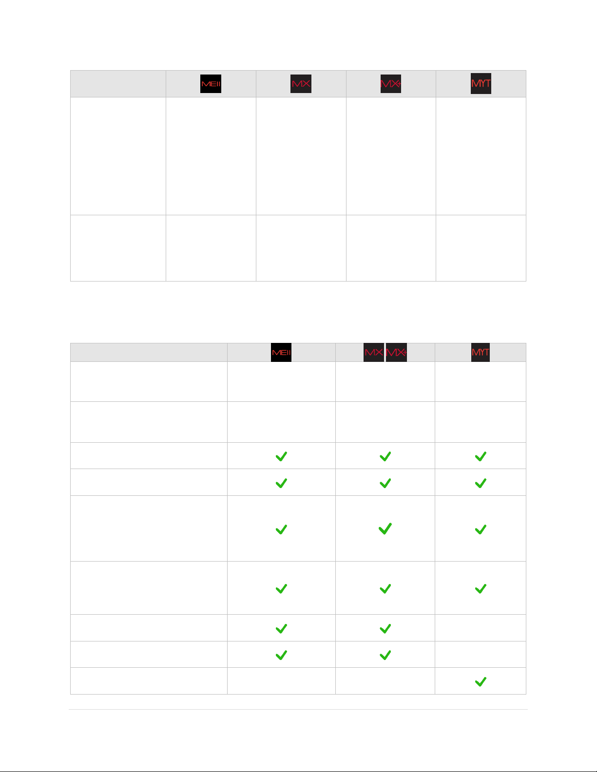
Optional Accessory
Counterweight Shaft Extension
Bar
8-in. long, 1.875-in.
wide
8-in. long, 1.5-in.
wide
Not available.
Counterweights
14 kg/30 lb.
18 kg/40 lb.
1.875-in. bore
9 kg/20 lb.
4.5 kg/10 lb.
1.5-in. bore
9 kg/20 lb.
4.5 kg/10 lb.
1.5-in. bore
Software Bisque Permanent Pier
48V 5AH Portable Power Supply
Power supply cables to use in
conjunction with the mount’s
built-in through the mount
power cabling (page 177)
Base to Pier Adaptor Plate for
mounting the Paramount to an
existing pier
Polar alignment scope, mounting
hardware, and cover
Not available.
Pyramid™ Portable Pier
Not available.
Paramount Mighty Tripod
Not available.
Not available.
Optional Accessories
The table below lists optional accessories for each model.
14 | P a g e
Paramount User Guide
Optional Accessory
Latitude Adjustment Wedge for
use below 10 degrees and above
about 64 degrees latitude
WiSky Wi-Fi Control
Absolute Encoders
Not available.
Not available.
Versa-Plate Spacers
Not available.
Not available.
Optional Software Add Ons and Databases
TheSkyX Professional Edition offers additional software Add Ons and astronomical databases.
For imaging system’s housed inside an automated astronomical dome, consider the optional
TheSkyX Professional Edition Dome Add On (http://www.bisque.com/dome) to automatically keep
the dome aligned to, and track with the mount. (The Dome Add On is included with all Paramount
ME IIs shipped after January 2015.)
TheSkyX Professional Edition Database Add On (http://www.bisque.com/DatabaseAddOn) offers
over 200 GB of astronomical catalogs.
Getting Help
If you have questions about your Paramount, please first carefully review the information in this
document. If you still cannot find an answer, please join the Software Bisque at www.bisque.com/support
and click the Write a New Post link on the Paramount ME II Support Forum
(http://www.bisque.com/sc/forums/114.aspx), the Paramount MX/MX+ Support Forum
(http://www.bisque.com/sc/forums/96.aspx), or the Paramount MYT Support Forum to ask your
question. The Software Bisque monitors this forum between 9 a.m. to 4 p.m. Mountain Time MondayFriday and tries to respond to questions within 5 business days (usually faster). Other knowledgeable
community members are there to help outside regular office hours.
What You Need to Know
Successful operation of a Paramount requires a solid understanding of many basic astronomy concepts, a
familiarity with operating a GEM, as well as an understanding TheSkyX Professional Edition.
If you are new to the Paramount, operating a GEM, or just getting into astronomy, please peruse the
following section. Based on years of support feedback, even experienced observers often do not
understand fundamental concepts as they relate to operating a Paramount.
15 | P a g e
Paramount User Guide
What are the differences between right ascension, azimuth and hour angle?
Why does the meridian matter when operating a GEM?
What exactly is synchronization?
What is homing and what does it actually do?
What is mount parking?
How does atmospheric refraction affect mount performance?
Why is polar alignment so important?
In addition to these basic questions, if you have never controlled a robotic GEM with TheSkyX Professional
Edition, please carefully read the following sections and then use TheSkyX Professional Edition’s Telescope
Simulator feature before setting up, connecting to, and operating the Paramount.
Coordinate Systems
The three most common coordinate systems used when working with equatorial mountings are described
below. Making sure you understand the differences between each system now will really help
troubleshooting issues in the future.
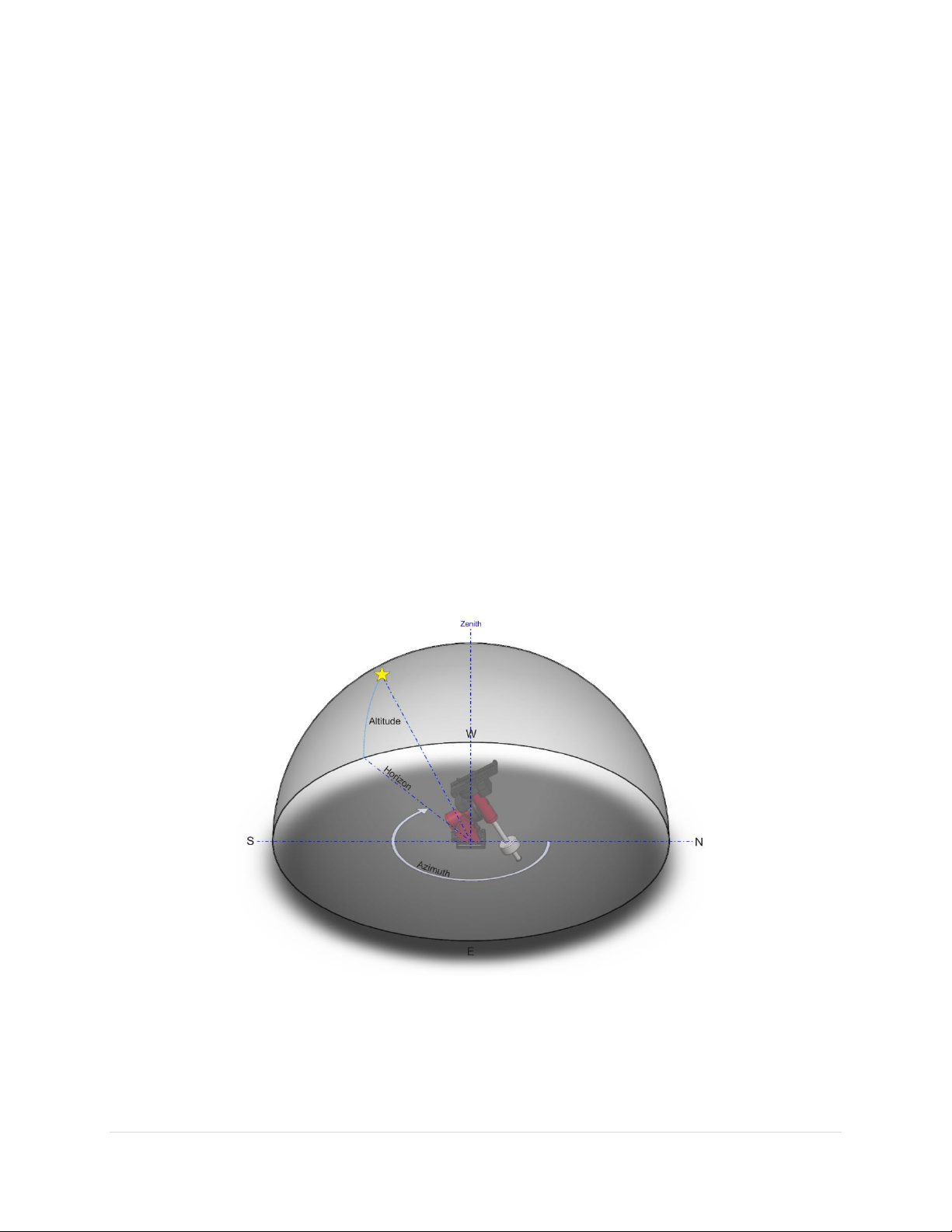
The Horizon Coordinate System
The horizon or “horizontal” coordinate system is used to specify the position of celestial objects relative
to the local horizon.
Figure 1: The horizon-based altitude and azimuth coordinate system.
Altitude
The altitude (alt) of an object is expressed as the number of degrees from the horizon (the ground at a
far distance) to the object, and is always between minus 90 and plus 90 degrees. Objects that have a
16 | P a g e

Paramount User Guide
negative altitude are below the horizon. For example, the Sun just after sunrise is close to the horizon so
it has an altitude of a couple of degrees, and just after sunset its altitude is minus one or two degrees.
Azimuth
The azimuth (az) of an object is generally reckoned from North, increasing in the clockwise direction, and
ranges from 0 to 359 degrees. North is 0 degrees, east is 90 degrees, south is 180 degrees and west is 270
degrees.
When the Paramount is controlled by TheSkyX Professional Edition, attempting to slew the mount below
the local horizon is not permitted and will result in an error message.
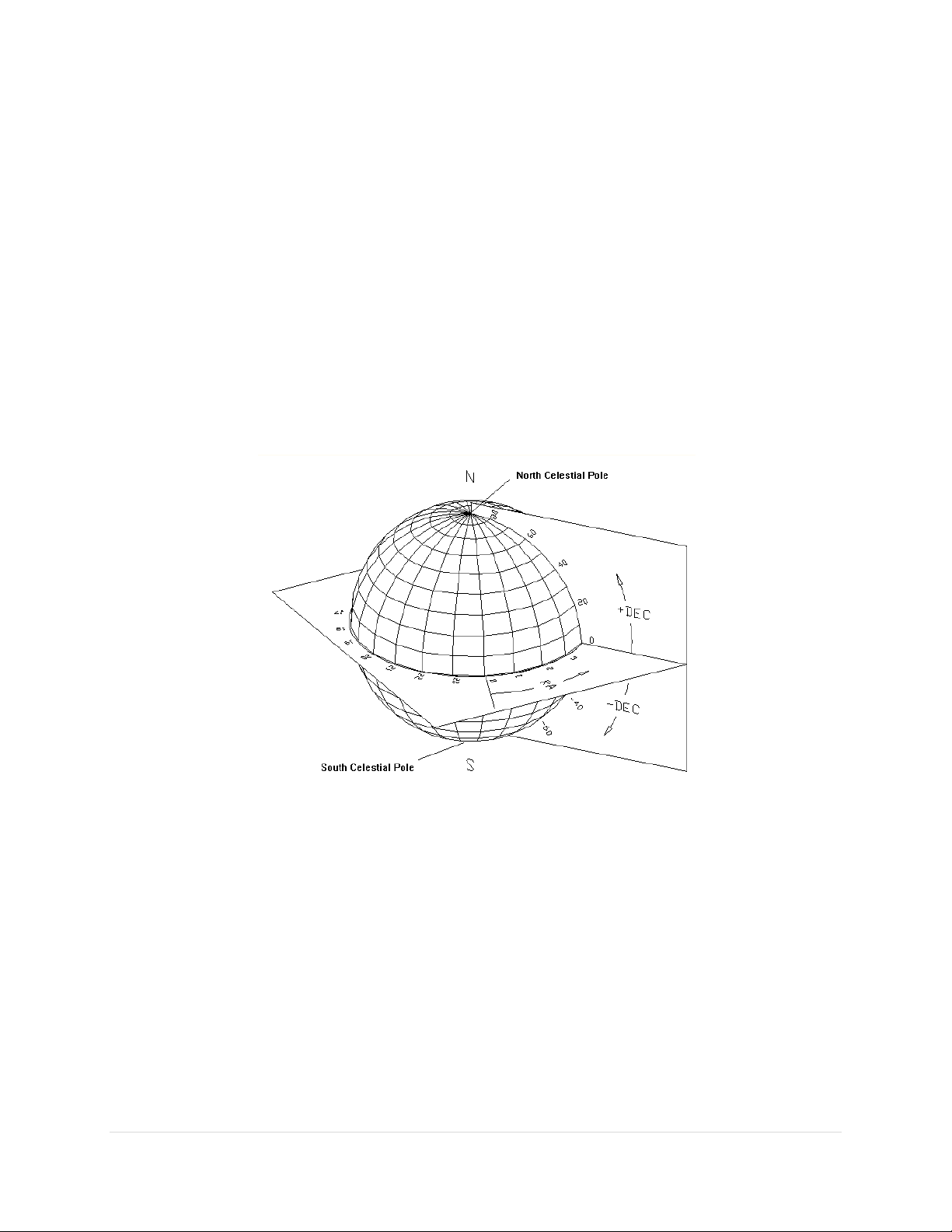
The Equatorial Coordinate System
The horizon coordinate system is not convenient for specifying the location of celestial objects because
the horizon coordinates of stars and other objects are continuously changing with time (due to the
rotation of the Earth).
The exception occurs with objects near the north and south celestial poles. These positions are unique
since they are near to the axis of rotation of the Earth and therefore move only in small circular paths.
Polaris, the North Star, for example, remains at a nearly constant altitude and azimuth. In the equatorial
coordinate system, the coordinates of all celestial objects remain fixed* from hour-to-hour, day-to-day
and so on.
An object's equatorial coordinates remain the same regardless of from where on Earth the object is
viewed. This allows astronomers to create star maps that apply to any place on Earth, or publish the
anticipated position of an upcoming comet so that astronomers everywhere know where it is located
among the stars.
The equatorial coordinate system used to specify the positions of celestial objects is directly analogous to
the latitude-longitude coordinate system used on Earth. In fact, if you were to expand the latitude and
longitude grid of the Earth so that it is out beyond all stars, you would have a sphere with identical
geometry to the celestial sphere.
We suppose that all stars and deep-sky objects are located on a very large sphere (out beyond all stars).
We call this the celestial sphere. For purposes of describing the positions of celestial objects, we consider
all stars and deep sky objects to be on the celestial sphere, when actually they are all positioned at varying
distances from the Earth.
* Equatorial coordinates change over long periods of time due to precession (wobbling of the Earth).
TheSkyX computes this change in stars’ position for the current date. Precession, however, does not
change the relative positions of objects with respect to one another.
17 | P a g e
Paramount User Guide
Right Ascension
The geometry of the right ascension (RA) lines on the celestial sphere is the same as the longitude lines
on Earth. Longitude lines divide the Earth into 360 degrees. Right ascension lines divide the celestial
sphere into 24 hours, based on one revolution of Earth. Therefore one hour of right ascension equals 15
degrees (360 divided by 24). See the definition of Local Sidereal Time for additional information on why
24 hours are used for right ascension instead of 360 degrees.
Zero degrees longitude passes through Greenwich, England and is the designated reference line for
longitude. What, then, is the reference line for zero hour’s right ascension? Astronomers use the vernal
equinox, the location where the Sun crosses the celestial equator during its apparent annual motion
against the background stars, as a "starting point" for right ascension.
The term "right ascension" comes from the fact that when viewed from the equator, all stars rise (or
ascend) at right angles to the horizon, so their times of rising are called their times of right ascension.
Figure 2: Right ascension and declination relative to the celestial sphere.
Declination
The declination (dec) lines on the celestial sphere are similar to latitude lines on Earth, ranging from –90
degrees to +90 degrees. The “declination” of an object is the angle measured from the celestial equator
(0 degrees declination) along a meridian line through the object. Polaris, the North Star has a declination
of just over 89 degrees so it is very close to the north celestial pole.
Hour Angle
Hour angle (HA) is measured from the meridian westward, along the celestial equator and uses the same
units as right ascension (hours, minutes, and seconds). A celestial object on the meridian is located at
hour angle 0. Six hours of time later, the object is located at hour angle +6. Twelve hours later, when the
object rises, its hour angle is –6 h.
18 | P a g e

Paramount User Guide
Hour angle can be used to describe a telescope’s mechanical orientation with respect to a horizon-based
hemisphere. For Paramount mounts with AutoHoming™, when the mount finds home, the home position
is a fixed, mechanical mount orientation. In the northern hemisphere, when homing is successful, the
mount always points to hour angle 2 and declination 0.
Smaller hour angles equate to positions of optimal observing, so your telescope will probably spend a
great deal of the time pointing to and tracking objects near hour angle zero (or, near the meridian).
Note that TheSkyX Professional Edition can be used to configure the Paramount’s “flip hour angle” (page
122) in order to maximize the length of time an object can be tracked past the meridian.
Local Sidereal Time
Local sidereal time (LST) is always equal to the instantaneous right ascension of the local meridian. When
you know the LST, you can look at star maps and determine which objects are near the meridian (those
with a right ascension close to the LST). For example, if the LST is 6:10:00, this means that stars with a
right ascension of about 6 hours are visible along the meridian.
If everyone reckoned time based on the Sun crossing the meridian, then each longitude on earth would
have a different time of day. That means noon, or the time the Sun crosses the meridian, would come a
few minutes earlier for someone living 60 miles to the east. Only those people living at the same longitude
would share a common time.
In the late 1800’s time zones were established to minimize the problem of having different time in
populous regions. The time within these zones is called zone time. Zone time places all locations on Earth
into various time zones. By definition, time zone zero is at zero degrees longitude, and the time zone
increases by one hour every 15 degrees longitude moving east, or decreases by one hour moving west.
The Paramount relies on TheSkyX Professional Edition having the correct time zone for your observing
site. When TheSkyX Professional Edition’s time zone is not correct, the position of the telescope cross
hairs will be offset by the time zone hour error when viewing horizon-based Sky Charts.
Atmospheric Refraction
The effects of atmospheric refraction on the position of celestial objects, as well as its effect on the
sidereal tracking rate, are often overlooked or even ignored by many amateur astronomers.
The refraction nuisance (and other system errors like tube flexure) means the “sidereal tracking rate” is
simply not good enough to precisely track objects. Refraction also displaces the position of the celestial
pole and makes precise polar alignment more difficult.
Some other interesting and significant facts about how refraction affects an object’s apparent position
include:
For a sea-level site, the refraction at 45 degrees zenith distance (ZD) is about 60 arcseconds (one
arcminute).
19 | P a g e

Paramount User Guide
For optimal performance, the equatorial axis of a GEM must be aligned to the refracted pole
to within 100 arcseconds.
If the mount’s equatorial axis is not “closely” aligned with the celestial pole…
Stars will drift in of the field of view, mostly in declination; quickly when polar
alignment is particularly poor.
When you tell TheSkyX Professional Edition where the mount is pointing, through a
process called “synchronization” (page 25), the synchronization results will be
incorrect, or “skewed” by the amount of the polar alignment error. For example, if
the polar axis is ten degrees “low” in altitude, then the resulting synchronization
positions computed by TheSkyX Professional Edition will be off by this same amount
in declination. The result is that the mount will not point with any accuracy or
repeatability.
Except low down in the sky, the refraction goes roughly as the tangent to ZD, so at ZD = 70 degrees,
or, at 20 degrees above the horizon, it is up to 165 arcseconds. (It reaches a 1800 arcseconds, or
0.5 degrees at the horizon.)
Refraction is proportional to pressure, so at high-altitude sites the refraction comes down
significantly. For example at Mauna Kea, 4,205 meters above sea level, the refraction is about 60
percent of the sea level amount.
Refraction is roughly inversely proportional to absolute temperature, so at –5C the refraction is
about 10 percent more than at 20C.
Humidity has little effect in the optical, though it matters a lot at radio wavelengths.
The color of the observed object matters, blue being refracted a few arcseconds more than red
at ZD 70.
When you use your Paramount to take long, unguided exposures at modest or longer focal lengths,
refraction becomes an important source of tracking error that is not taken into account in the standard
sidereal tracking rate.
TPoint can be employed to take care of the atmospheric refraction details for you.
TPoint’s Super Model feature and Polar Alignment Report automatically determines the position
of the refracted pole and give recommendations on how to proceed, including how much to rotate
the altitude and azimuth knobs when adjustment is necessary.
It accounts for and applies refraction when acquiring telescope calibration data as well as corrects
the telescope’s position when the mount is slewed.
TPoint’s ProTrack™ feature can be used to apply tracking corrections to the mount based on the
point calibration data.
Polar Alignment Basics
20 | P a g e
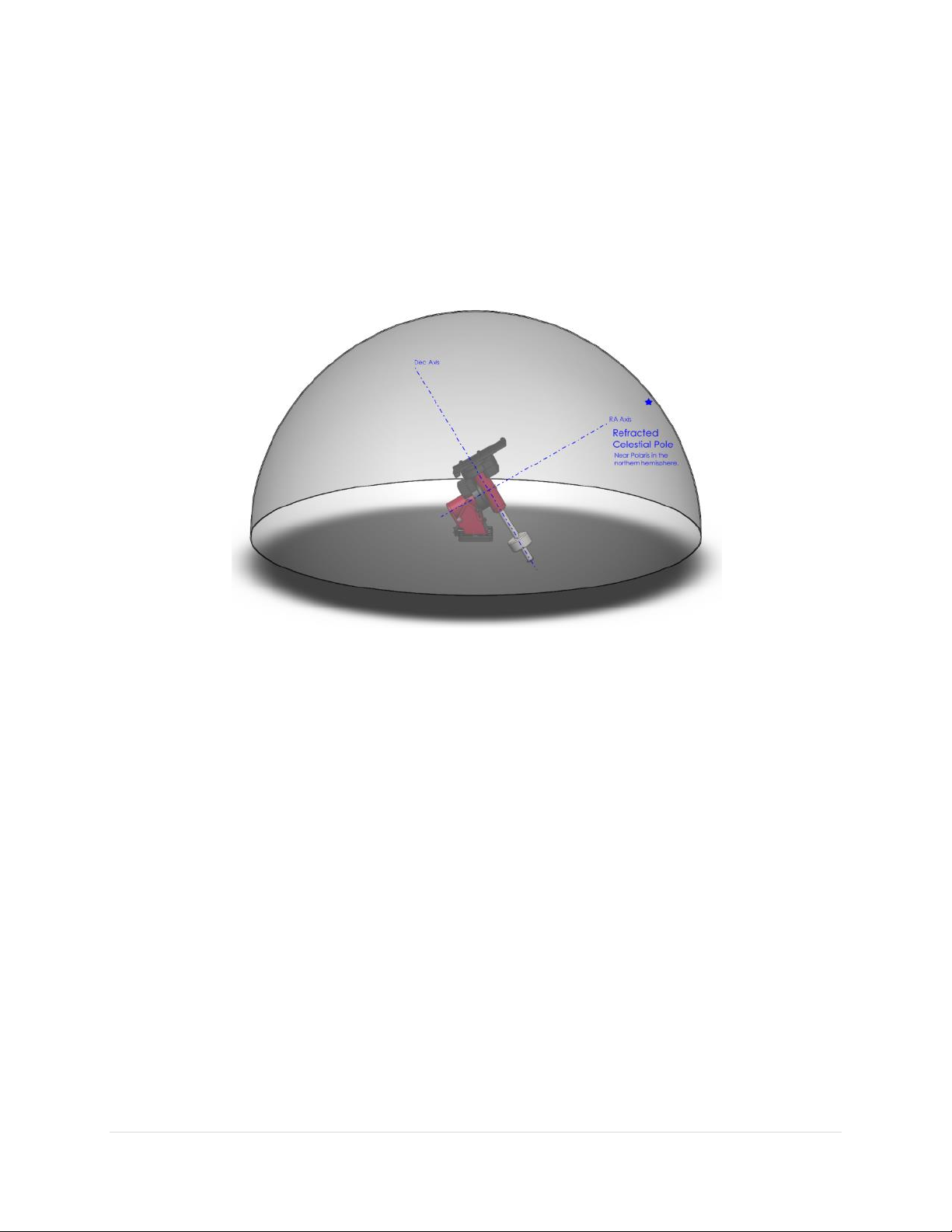
Paramount User Guide
The mount’s “TPoint unassisted pointing accuracy” will be disappointing, especially
when the OTA switches sides of the pier.
These symptoms may make you frustrated with the performance of your Paramount and
leave you wondering, “What am I doing wrong?” Mastering the polar alignment techniques
described below (or using your trusted method) is critical.
Step 1
Use the “Rough Polar Alignment Method” (page 113) to align the mount’s polar axis to
within five arcminutes of the pole, even during daylight.
Step 2
If the pole is visible, and you have a polar alignment scope (page 115), use it to roughly
align the mount to the celestial pole.
-Or-
Use the TPoint Add On to quantify the mount’s polar alignment error. The TPoint Add On’s
Polar Alignment Report indicates exactly how much the altitude adjuster (page 93) and
azimuth adjuster knobs (page 93) need to be rotated so that both axes are aligned to the
refracted pole.
Figure 3: Paramount aligned with the refracted celestial pole in the northern hemisphere.
Software Bisque recommends the following polar alignment methods to ensure efficient and optimal
polar alignment.
See “How To Polar Align” on page 112 for the best ways to achieve optimal polar alignment.
21 | P a g e
Paramount User Guide
Mount synchronization is one of the least understood and most confusing processes for new
Paramount users; understanding exactly what homing a Paramount does is a very close
second. Please carefully read the following to avoid falling into the “my mount is not homing
to the correct position” trap.
The home position is located at hour angle 2 and 0 degrees declination. The
home position is a fixed, mechanical orientation and cannot change; it is
defined by the physical position of the gears relative to fixed internal
homing sensors. See “Physically Marking the Home Position” on page 24
for a simple procedure to demonstrate the mount’s absolute home
position.
If the mount is not physically pointing to approximately hour angle 2 and 0
degrees declination after finding home, then either the Versa-Plate is
mounted incorrectly, the mount’s polar axis is not oriented north-south.
If, after homing is complete, the coordinates of the telescope cross hairs
displayed by TheSkyX Professional Edition indicate that the mount is pointing
anywhere other than the home position, then either TheSkyX Professional
Edition’s location, date, time or time zone is not correct, or the mount has been
synchronized incorrectly. See “Synchronization” on page 25 for more
information.
The Paramount cannot slew and will not track at the
sidereal rate until after the mount is successfully homed.
Homing
Finding the home position, or “homing” the Paramount is an automated initialization process. When the
Paramount control system receives the “find home position command”, the mount’s right ascension and
declination axes are slewed to an absolute, mechanically fixed orientation.
Homing must be performed every time the Paramount is powered on so that the control system can
establish the mount’s position and restore the synchronization information, when possible.
Once the mount is homed, and the previous session’s synchronization information is applied by TheSkyX
Professional Edition, the telescope will know its orientation and have the same pointing accuracy as the
last observing session.
When a Find Home command is issued from the hand controller (by double-tapping the button on the
end of the joystick handle, see page 108 for details) or TheSkyX Professional Edition (page 119), the mount
slews to the home position and zeros the control system’s “position registers”. When the mount is
subsequently synchronized on a star, the computed hour angle and declination of the home indices are
stored in the internal flash of the Paramount’s control system.
22 | P a g e

Paramount User Guide
Subsequent observing sessions use TheSkyX Professional Edition’s local sidereal time to determine the
mount’s equatorial coordinates. Make sure the computer’s clock is accurate (page 29).
Homing provides the following benefits.
Once a mount is aligned with the celestial pole and homed, repeatable and accurate pointing from
night to night can be achieved using TheSkyX Professional Edition and the TPoint Add On.
After homing, the mount “knows” its orientation and therefore cannot be slewed into the pier
(see “Software Slew Limits” on page 159).
The control system’s periodic error correction (PEC) uses this information to calibrate the control
system’s internal PEC table with the orientation of the worm gear.
The mount’s orientation can be restored after power outages or other communication
malfunctions.
The home position can be used to align the polar axis to the celestial pole (see “Rough Polar
Alignment Method” on page 113).
Labeling the Home Position on the Sky Chart
Synchronizing the mount (page 25) on the wrong star or configuring TheSkyX Professional Edition to use
the wrong location, date, time or time zone for your location means the Paramount will be “lost in space”.
The telescope cross hairs will appear in the “wrong” place on the Sky Chart and the mount will apparently
not slew to the correct coordinates when commanded to do so. If the coordinates of the telescope cross
hairs do not match the actual physical orientation of the Paramount, or it does not slew to the correct
coordinates, you will be scratching your head wondering what is wrong. The next step is to post a support
question asking, “Why is my mount pointing to the wrong coordinates?”
For this reason, Software Bisque strongly recommends creating a label that shows the location of the
mount’s absolute home position (page 149) directly on the Sky Chart to provide a constant visual reminder
of where the telescope cross hairs must be after finding home.
If, after homing the mount, the telescope cross hairs do not end up very near hour angle 2 and declination
0 (or hour angle –2.0, declination 0 in the southern hemisphere), either TheSkyX Professional Edition’s site
information is wrong or the mount has been synchronized on the wrong star.
Remember, the absolute home position of the Paramount cannot change. So, if the mount’s relative home
position is wrong (or the telescope cross hairs do not appear in the correct location on the Sky Chart),
please double check the synchronization (page 25) and TheSkyX Professional Edition’s location, date and
time settings for your location before submitting a support request.
To Label the Home Position in Software
The following procedure assumes this is a first time mount synchronization.
1. From TheSkyX Professional Edition, choose the Location command from the Input menu and make
sure the settings on the Custom tab match your observing site.
2. Choose the Verify TheSkyX Time command from the Tools menu to make sure you computer’s
time matches an independent time source.
23 | P a g e

Paramount User Guide
3. Choose the Connect command from the Telescope menu. The mount Status text will show Not
Homed.
4. Choose the Find Home command from the Start Up pop-up menu on the Telescope window. The
mount will slew to the home position. The mount Status text will show Not Synced.
5. Choose the Turn Tracking Off command from the Tools pop-up menu on the Telescope window.
Turn tracking off to pin the mount to this position.
6. Choose the TPoint Add On command from the Telescope menu.
7. Then turn off the Apply Pointing Corrections checkbox on the Setup tab and click Close. TPoint
will change the position of the telescope cross hairs based on the current model and we want the
label to show the “unmodeled” cross hair position.
8. Click on the center of the telescope cross hair and note the exact altitude and azimuth of this
position. This is the horizon-based coordinate of the home position.
9. Choose the My Chart Elements command from the Input menu.
10. Click the Add Object button (the upper-left most button on the Manage tab), then click the Add
and Edit button to add an object to the Sky Chart.
11. On the Add/Edit Chart Element window, turn on the Horizon radio button, then enter the azimuth
(Azm) and altitude (Alt) of the telescope cross hair. In the Label text box, enter the text Absolute
Home Position and then click OK.
The Sky Chart now shows a label at the absolute home position of the mount. To double-check the
accuracy of this position, choose the Find Home command. Note that, when compared to the absolute
home position, the position of the telescope cross hairs on the Sky Chart will also be affected by the
following:
Synchronizing the mount on a star introduces small pointing errors.
A TPoint pointing model will change the position of the telescope cross hairs based on the pointing
calibration data.
The above two items necessarily introduce a small offset between the mount’s absolute home position
and the position of the telescope cross hairs after finding home (once the mount has been synchronized
and a TPoint model is established).
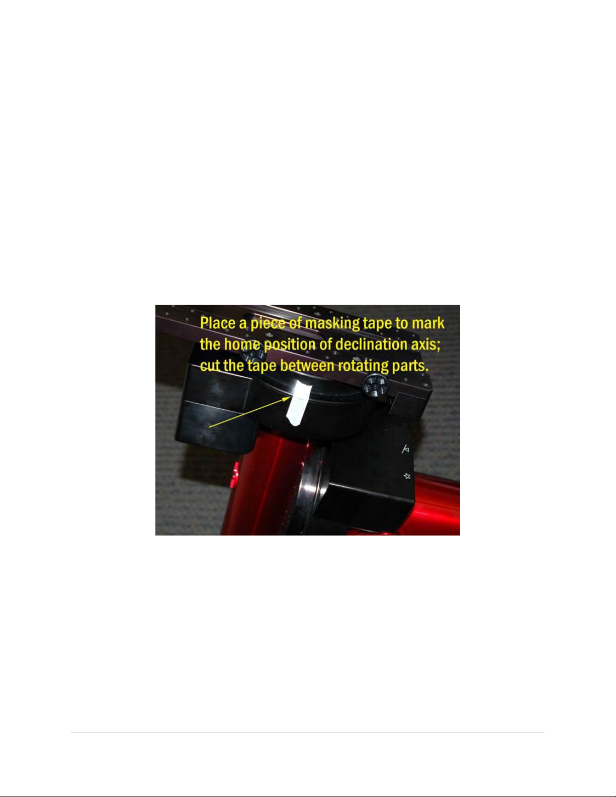
Physically Marking the Home Position
If, after finding the home position, the cross hairs that are displayed on the Sky Chart are at the wrong
coordinates, one or more of the following is probably true:
The mount is not aligned to the celestial pole. (Believe it or not, Software Bisque has had several
support cases claiming that the mount could not point the telescope correctly, only to discover
the Paramount’s polar axis was mounted in the wrong direction; for example, the polar axis was
pointing south in the northern hemisphere, in other words, 180 degrees off.)
The optical tube assembly is mounted “backwards” on the Versa-Plate.
In TheSkyX Professional Edition’s location, date, time, time zone or Daylight Saving Time settings
are wrong for your observing site.
24 | P a g e
Paramount User Guide
The wrong star was centered in the eyepiece when the mount was synchronized. Improper
synchronization results in the telescope cross hairs to be displayed at the wrong spot on the Sky
Chart. And this error is particularly apparent after the mount is homed.
Many come to the incorrect conclusion when the telescope cross hairs on the Sky Chart are wrong, there
must be something wrong with the homing process. Homing is generally very reliable and rarely fails. The
procedure below demonstrates that, after homing, the Paramount is always in the same mechanical
position.
1. Home the mount.
2. On each axis, place a piece of masking tape over the rotating portion and cut the tape between
the rotating parts of the mount. The “vertical” edges of the tape mark the home position in that
axis.
3. Use the joystick (or TheSkyX Professional Edition) to slew the mount to any orientation.
4. Double-tap the joystick to find home again.
Figure 4: Marking the Paramount’s home position.
The Paramount will dutifully return to the identical position in each axis.
This “homing repeatability test” will hopefully provide confidence that, after finding home, the mount is
always pointing to hour angle 2 and declination 0 (in the northern hemisphere), and will help narrow down
the actual causes of pointing errors (most commonly, an invalid synchronization, incorrect settings in
TheSkyX Professional Edition, or poor polar alignment).
Synchronization
Synchronizing (or “syncing”) the Paramount initializes the control system to a specific equatorial
coordinate. In short, you tell the mount, “You are here!” Synchronization involves centering a known star
25 | P a g e

Paramount User Guide
Consider using a GPS to also obtain your site’s latitude and longitude. Make sure
the time zone and daylight saving options are correct for your location (a GPS does
not supply this information).
in the eyepiece, identifying this star in TheSkyX Professional Edition then choosing the Synchronize
command from the Start Up pop-up menu on the Telescope window.
Once the Paramount has been synchronized on a star, TheSkyX Professional Edition uses the equatorial
coordinates of the star to determine the mount’s mechanical orientation and software slew limits.
TheSkyX Professional Edition stores this synchronization position so that the mount’s orientation can be
restored in subsequent observing sessions.
In theory, after a permanently mounted Paramount is aligned with the celestial pole (page 20), it need be
synchronized only once. In practice, the mount will have to be synchronized:
Each time the mount is setup for portable use.
When the mount’s polar alignment is changed.
When the optical tube assembly (OTA) is changed.
Synchronization is an essential first step to “normal” mount operation. If the mount is not synchronized
correctly, the actual orientation the telescope will not match the simulated telescope’s position on the
Sky Chart. And, when commanded to slew from TheSkyX Professional Edition, the telescope will end up
pointing at the wrong place in the sky.
Best Synchronization Practices
Do not synchronize on stars near the celestial pole – The celestial pole represents a point of
“singularity” on the celestial sphere. As a best practice, do not synchronize on Polaris (in the
northern hemisphere) and avoid stars above 60 degrees declination or so.
Use brighter, easily identifiable stars – Fainter stars can be hard to identify, making
synchronization more difficult.
Step by Step Synchronization
Carefully follow the procedure below to ensure that synchronization is performed correctly. If you make
a mistake and point the telescope at the wrong star, for example, see “Starting Synchronization Over” on
page 29 to restore the default settings and try again.
1. Set the computer’s clock accurately. Accurate time is crucial for consistent, accurate pointing and
synchronization. Consider using an Internet time server or a GPS-based clock to regularly update
your computer’s clock and keep it accurate. See “The Local Celestial Meridian” on page 29 for
more information.
2. Choose the Location command from the Input menu to set the observing site’s latitude, longitude,
time zone and Daylight Saving option if necessary.
26 | P a g e

Paramount User Guide
Errors in latitude “appear” to TPoint as a vertical misalignment in the polar axis,
and will pollute synchronization (and the TPoint model, if one is in place).
If your time zone is off by one hour or more, then pointing will be off by the
same amount.
If the wrong Daylight Saving Option is selected, then time will be off by an hour
(or more) and the mount will not slew to the correct position.
3. Choose the Connect command from the Telescope menu.
4. Choose the Find Home command from the Start Up pop-up menu on the Telescope window.
5. Locate an easily identifiable, bright star to use for synchronization.
Partial clouds or twilight can make this task more difficult than it might seem. The Paramount can
be synchronized to virtually any position on the celestial sphere on the east or west side of the
meridian (See “Best Synchronization Practice” on page 26).
6. Center the bright star in the eyepiece, photo or video display using the joystick on the hand
controller or TheSkyX Professional Edition’s Motion Controls on the Telescope window.
7. From TheSkyX Professional Edition, enter the name of the bright star in the Search For text box
and click the Find button on the Telescope window to identify the star. Or, click on the star if it is
visible on the Sky Chart.
8. Choose the Synchronize command on the Start Up pop-up menu in Telescope tab. When the
Telescope Synchronization window appears, click the Sync button.
The mount is now synchronized on the bright star.
Session to Session Pointing Repeatability
In subsequent observing sessions, TheSkyX Professional Edition computes the current equatorial and
horizon coordinates of the telescope using the stored hour angle and declination of the mount and the
local sidereal time. In fact, the Paramount’s pointing accuracy should be virtually identical from session
to session.
Please verify the repeatability of the Paramount pointing before proceeding (this test assumes that the
mount’s polar axis is aligned with the celestial pole):
1. Turn the mount off.
2. Turn the mount on (this terminates communication between TheSkyX Professional Edition and
the Paramount).
3. Home the mount.
4. From TheSkyX Professional Edition, choose the Connect command from the Telescope menu. The
telescope cross hairs appear at the relative home position (see page 149 for an explanation of the
difference between the absolute and relative home position).
5. Slew the mount to the star you just synced on. The mount should slew back to this star; that is, it
should return to the same position in the eyepiece, video or CCD detector. In practice, there may
be small pointing errors that are introduced by mirror flop, or slight differences in time, so the
star may not be in exactly the same position, but it should be very close.
27 | P a g e
Paramount User Guide
Note that during the process of polar alignment, you will be required to synchronize the mount several
times (each time the mount is adjusted to a new altitude and/or azimuth). For permanent installations,
once the mount is sufficiently aligned with the celestial pole, it should not have to be synchronized again
unless the optical tube assembly or the telescope’s physical mounting changes.
Portable setups must synchronize the mount each session, or, if a TPoint pointing model will be used, a
Portable Recalibration, as described in the TPoint Add On User Guide, must be performed first.
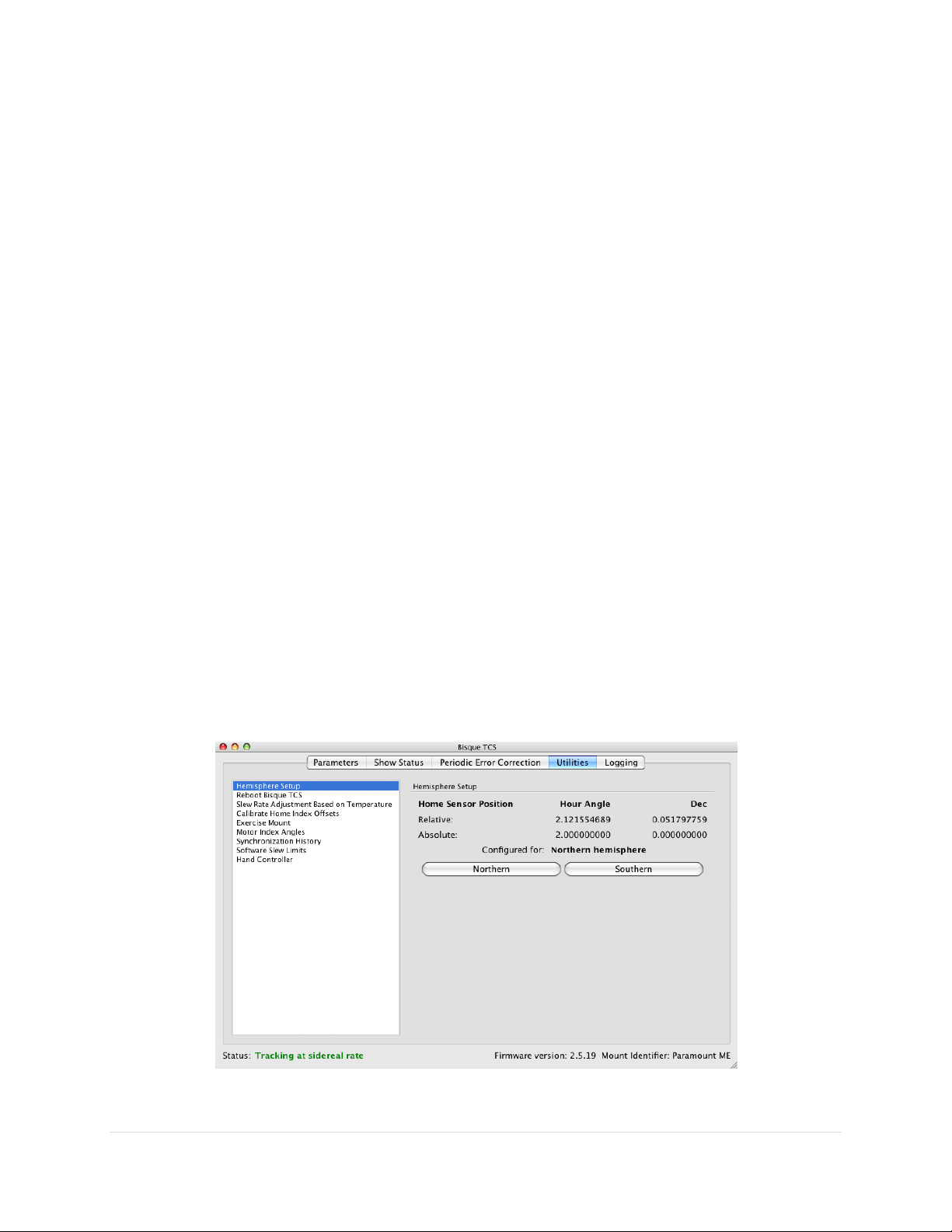
Making Sure Synchronization Is Correct
The first step to ensure the Paramount is properly synchronized is to look at the hour angle and the
declination of the homing sensors reported by TheSkyX Professional Edition.
When the mount has been properly synchronized, TheSkyX Professional Edition’s relative position of the
home sensors should approximately match the absolute position of the home sensors. Remember, the
mount’s absolute home position cannot change, so TheSkyX Professional Edition’s reported home position
must be near hour angle 2 and declination 0 in the northern hemisphere. If TheSkyX Professional Edition
reports a relative home position that is significantly different from hour angle 2 and declination 0, then
the mount’s synchronization is wrong. A small difference is okay, it just means that your
telescope/eyepiece/camera is not perfectly aligned with the mount’s axes.
See “Starting Synchronization Over” on page 29 to restore the default settings and resynchronize the
mount.
Note that the above description assumes the Paramount is located in the northern hemisphere and the
Versa-Plate is mounted in the standard orientation (page 65). When the Versa-Plate is mounted in the
wide orientation, then reported home position will be 90 degrees from hour angle 2.
28 | P a g e
Figure 5: The absolute and relative homing sensor positions.

Paramount User Guide
The Sky Chart provides graphical feedback to help verify the mount is synchronized correctly and identifies
the regions near the meridian that have unique behavior when tracking or slewing. While TheSkyX
Professional Edition is connected to the Paramount, two regions are drawn near the meridian. If the
regions are centered on the meridian, then the synchronization is most likely correct.
Purple Region
When the optical tube assembly is on the east side of the mount (pointing to the west), the purple region
(that is, the region on the east side of the meridian) indicates the area where the mount can be slewed
beyond the meridian without flipping sides. If the OTA is on the east side, and you attempt to slew beyond
this region, the mount automatically flips sides.
Red Region
When the optical tube assembly is on the west side of the mount, the red region indicates how far past
the meridian the mount can track before encountering a software or hardware limit. If the OTA remains
on the west side and the mount tracks to the tracking limit, then tracking is turned off. Note that the
Paramount will not automatically flip sides of the meridian and continue tracking in this situation. The
red region also indicates the area where, when the OTA is on west side, the mount can be slewed past the
meridian without flipping sides.
Synchronization Checklist
Make sure that the computer’s time is accurate, and that TheSkyX Professional Edition is
configured to use the computer’s clock.
Verify that synchronization is performed using the star listed in TheSkyX Professional Edition’s
Object Information Report. When clicking the Sky Chart to identify an object, the Object
Information Report can list other objects that are “near” the mouse click position.
In general, avoid synchronizing on a star that is located near the meridian.
Avoid synchronizing on stars above 60 degrees declination.
Starting Synchronization Over
If you are ever unsure about synchronization, you can start over by:
1. Choose the Connect command from the Telescope menu.
2. Choose the Bisque TCS command from the Tools pop-up on the Telescope window.
3. On the Bisque TCS window, click the Utilities.
4. Select Synchronization History on the left side of the window.
5. Click the Clear button to clear the existing synchronization.
The Local Celestial Meridian
The local celestial meridian is a great circle on the celestial sphere that runs from the zenith directly
overhead to a point due South on the horizon, continuing around to the nadir (directly below) and back
up to the zenith. This line divides the celestial sphere into east and west hemispheres.
29 | P a g e
Paramount User Guide
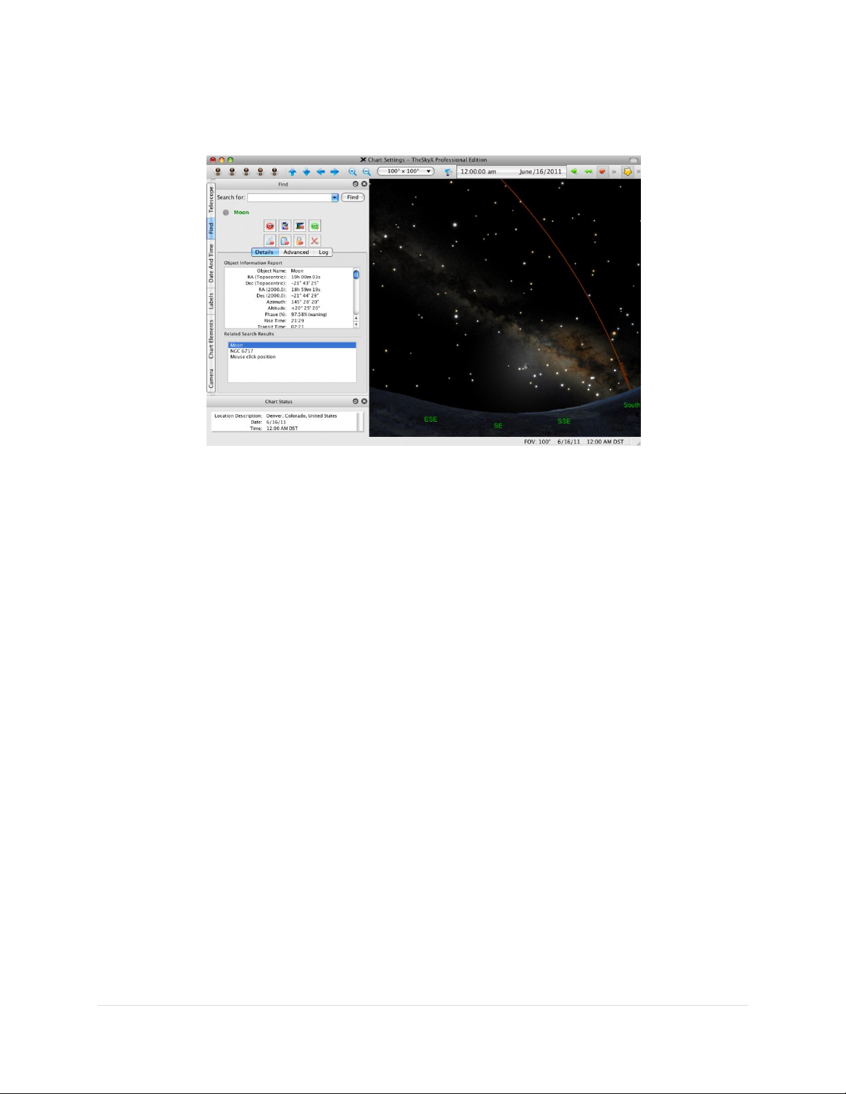
From TheSkyX Professional Edition, expand Reference Lines and Photos in the Chart Elements window
and turn on the Meridian checkbox.
Figure 6: TheSkyX Professional Edition with the meridian reference line turned on.
The arcing line in Figure 6 represents the local celestial meridian. When the Paramount is at the home
position, the telescope must be pointing to the west side of the meridian, near hour angle 2 and
declination 0 in the northern hemisphere. (Or, hour angle –2.0 and declination 0 in the southern
hemisphere).
If the optical tube assembly is not pointing to the home position, or if the telescope cross hairs in the
TheSkyX Professional Edition indicate that the home position is anywhere else (by more than a few
arcminutes or so), then one or more is the case:
TheSkyX Professional Edition is not configured correctly for your location.
The Versa-Plate is mounted in the wide configuration (page 65).
The Versa-Plate is mounted 180 degrees off.
Before continuing, make sure that TheSkyX Professional Edition’s location, date, time, time zone, and
Daylight Saving Option are correct. Also make sure the Versa-Plate is mounted in the correct orientation
before proceeding.
Maintaining Accurate Time
The Paramount can provide very accurate all sky pointing during a single session without an accurate time
base (that is, if the computer’s clock is accurate to one or two minutes or so). However, TheSkyX
Professional Edition must make decisions on how to slew to various positions in the sky based on the local
time. For example, an object that is on the east of the meridian may require the telescope be slewed to
west side of the pier and vice versa. So, maintaining accurate time is important.
30 | P a g e

Paramount User Guide
Always perform “reality check” by comparing the coordinates of objects in TheSkyX
Professional Edition to objects in the night sky. If TheSkyX Professional Edition’s
location or time is not accurate, the two will not match!
Choose the Verify TheSkyX Time command on the Tools menu to compare the
computer’s date, time and time zone settings with a web-based time source.
Initializing the Paramount requires a very accurate time base. TheSkyX Professional Edition uses the
computer’s clock to compute the local sidereal time (LST). When a connection is established between
TheSkyX Professional Edition and the “homed” Paramount, the LST is used to re-establish the
synchronization between the Paramount’s “electronic setting circles” and the celestial sphere to within a
few arcseconds. If the computer’s time is accurate, you can just power-up the mount, home, and then
start imaging each night.
Setting the Computer’s Clock
The best method to accurately set your computer’s clock is with “time server” software. Remember, each
second of error in time translates to fifteen arcseconds error in angular distance near the celestial equator.
So, telescope pointing will degrade if time is not accurately maintained from night to night.
Inaccurate time causes the mount to slew to objects ahead or behind objects in right ascension by a
consistent offset. Software that periodically resets your computer’s clock using an accurate time base
solves this problem.
Many applications maintain accurate time and most operating systems can be configured to update the
computer’s clock automatically. Windows users might consider Dimension 4 from Thinking Man Software.
Search the web for “time server software” to locate alternatives.
Parking the Paramount
Parking is a command that can be issued to the Paramount from TheSkyX Professional Edition and
performs the following operations:
1. After confirmation by the user, the mount is automatically slewed to a user-defined altitude and
azimuth coordinate, called the park position.
2. Once the park position is reached, the Paramount’s tracking is immediately turned off.
3. Communication between TheSkyX Professional Edition and the mount is terminated.
Note that the park position is not used to initialize the mount.
Parking from TheSkyX Professional Edition
From TheSkyX Professional Edition, connect to the mount, and then choose the Park command from the
Shut Down pop-up menu on the Telescope window. You will be asked to confirm that you want to slew
the mount to the park position and park the mount.
31 | P a g e

Paramount User Guide
Defining the Park Position
Before parking the Paramount, you need to define the park position. This is the position that the mount
will slew to when the Park command is issued from TheSkyX Professional Edition. Please carefully read
“XPark Position RulesX” below.
With a telescope link established, slew the telescope to the desired park position. From TheSkyX
Professional Edition, choose the Set Park Position command from the Shut Down pop-up menu on the
Telescope window. The park position needs to be set once; the coordinates of the mount (in
altitude/azimuth) are automatically saved for future parks.
Software Bisque recommends that, if possible, the telescope be parked as close to the home position as
practical. Since the Paramount must be homed at power up, the time required to find the home position
is reduced when the park position is near the home position.
Park Position Rules
The Paramount must be correctly synchronized before the mount is parked and before the park
position can be defined. Otherwise, the mount will not return to the correct park position.
When defining the park position near the meridian, make sure that the OTA is on the opposite
side of the meridian as the equatorial coordinate of the park position. In other words, never
define the park position when the counterweight shaft is “above” horizontal.
Here is an example of a situation that will cause unexpected parking behavior. Suppose you want
your telescope to always park in the same orientation “near” the meridian, with the OTA on the
east side (and the counterweights on the west side) of the mount. So, you slew the mount to a
location near the meridian that also happens to be on the east side of the meridian, and then
define the park position.
Since the Paramount allows the OTA to slew past the meridian (two hours maximum for the
Paramount ME II and 2.5 hours for the Paramount MX and Paramount MX+) before flipping sides,
you have now defined a park position that will cause the mount to slew to a different orientation
than when the park position was defined. In this example, when you park the mount, the control
system will still park the telescope near the meridian, but with the OTA on the west side (and the
counterweights on the east side) of the mount.
For mounts in the northern hemisphere, do not define the park position from due west to due
east (through north), and below the altitude of the celestial pole. For mounts in the southern
hemisphere, do not define the park position from due east to due west (through south) and below
the altitude of the celestial pole.
Audible Control System Feedback
Each time the mount is turned on the control system performs both an electronics and servomotor
initialization procedure, and emits different sounds based on the status of the initialization. A short
whistle is emitted immediately after the power switch is turned on and indicates successful initialization
32 | P a g e

Paramount User Guide
Sound
Occurs
Description
Short whistle
Immediately after turning
the power on.
The sound indicates the control system is operational.
Two beeps from
about two
seconds apart
Shortly after mount is
turned on.
Indicates that the control system has successfully located
the DC servomotor’s “index” position in right ascension and
declination. The mount is ready for normal operation.
Exactly when the two beeps occur will be
different for each mount and will vary depending
on the mount's current mechanical
orientation. The beeps may even occur
simultaneously so that only a single beep is
audible.
If the LEDs on the Electronics Box are illuminated,
and the mount homes, the control system is
functioning normally.
Single beep
When the servomotor
initialization is interrupted,
shortly after mount is
powered on.
Servomotor initialization can be interrupted by the
following actions.
Pressing and holding the joystick button down and
turning on the mount.
Moving the joystick from its center position before
the servomotors are initialized.
of the control system electronics; two successive beeps (usually occurring a few seconds or so apart)
indicate servomotor initialization success. The three LEDs on the Electronics Box, labeled TCS, RA, and
Dec, provide additional visual feedback of mount initialization. See “Electronics Box Components” on
page 78 for details.
The initialization procedure is terminated if the joystick button is pressed and held down when the mount
is turned on, or the joystick is moved from the center position before the servomotor initialization is
complete. In this situation, the mount emits a single beep. When initialization is interrupted for any
reason, the mount will not slew or track. Before attempting to slew or home the mount, make sure the
joystick is in the center position, power the mount off then on, and then wait for the two beeps that
indicate the mount is ready for normal operation.
The table below describes the different sounds that the mount can emit, when the sound occurs, and
explains what the sound means. Visit the Videos and Audio Clips page on the Software Bisque web site
to listen to recordings of these sounds. To get there, navigate to www.bisque.com, click the Downloads
link, then click the Video and Audio Clips link under Browse Downloads in the left column of the
Downloads page. The audible feedback recordings are listed on the right of the web page.
33 | P a g e

Paramount User Guide
Sound
Occurs
Description
Attempting to slew or home the mount from
TheSkyX Professional Edition before servomotor
initialization. For normal initialization, simply turn
on the mount and wait for the two successive
beeps, without attempting to control the mount via
joystick or TheSkyX Professional Edition.
One or both of the Three Position Switches is in the
Lock position (page 73).
Ba-dink (lower
pitch), ba-dink
(higher pitch)
Shortly after the mount has
slewed to the home position
in each axis.
Indicates that mount has successfully located the home
position (page 20).
Continuous,
successive, highpitched beeps.
May occur when attempting
to slew the mount.
This sound indicates a control system error condition if the
mount cannot slew. “Something” is preventing the
servomotors from rotating, so the mount cannot slew or
track normally.
Typical causes include:
The mount encountered a fixed object while
slewing. For example, the counterweight shaft has
run into a step stool that has been placed next to
the pier.
Payload is significantly out of balance and exceeds
the maximum torque output of the motor. Make
sure payload is balanced before proceeding.
Increased drive train torque demands during cold
temperature operation can prevent slews.
Single “click” or
“tic” sound
During communication with
TheSkyX Professional
Edition.
The Paramount will emit a single “click” (or “tic”) when
serial communications between the mount and TheSkyX
Professional Edition are interrupted. Interruption can
occur, for example, when a camera is downloading an
image, or during other processor intensive operations.
Notes:
The clicking noise is normal and expected behavior.
The clicking noise is not indicative of any problems
with the mount.
Audible feedback cannot be disabled.
34 | P a g e

Paramount User Guide
Sound
Occurs
Description
Variable-pitched
high-frequency
hum
After motor initialization
and whenever the mount is
powered on and tracking.
When the Paramount is turned on and initialized, the
servomotors emit an audible, variable-pitched “humming”
sound.
This sound is the result of the control system checking and
adjusting the position of the servo– about 3,333 Hz, and is
normal. This sound serves as the audible “heartbeat” of the
mount, and means that the electronics are powered and
functioning normally.
The Paramount through the mount cable conduits are intended to house cables that carry
low voltage and relatively low current direct current (DC) power, only.
Software Bisque recommends installing through the mount cables that carry a
maximum of +12V DC, 5.0A (60W max).
Never install through the mount cabling that carries an alternating current (AC)
power source; for example, +120V or greater at any amperage.
Always keep fingers clear from the cable conduit access hole!
While the declination axis rotates during mount slews,
an internal shaft in the declination assembly is also
being rotated by a very high torque servomotor.
When the declination axis is being balanced (page 73),
the internal shaft can rotate freely and may do so with a
high angular velocity when the mount’s payload is even
slightly out of balance.
Visual Control System Feedback
The three LEDs on the Electronics Box are illuminated based on the status of the control system. See
“Electronics Box Components” on page 78 for details.
Through the Mount Cabling
Digital imagers are familiar with the cabling “madness” that occurs when a myriad of devices, including
cameras, focusers, filter wheels, focusers, rotators, etc. are connected to the telescope. The Paramount
mount’s standard through the mount cabling, and through the mount cabling conduits can be used to
help tame cabling chaos.
35 | P a g e

Paramount User Guide
In both cases, the rotating internal shaft creates a potentially
dangerous pinch point with the outer declination axis
assembly that can cut, crush or sever fingers.
Always keep fingers clear during mount slews and use extreme
caution when routing cables through the mount, or aligning the
declination shaft’s “through-hole” during polar scope
alignment.
The Paramount allows custom cables to be passed through the mount, entering at the cable conduit
through the right ascension and declination axis up to the top of the declination axis and out to the
Instrument Panel. Routing cables through the mount has many advantages, particularly during remote
operation.
Most imaging systems have numerous cables draped from somewhere near the telescope to the
observatory floor. These cables are prone to snag “something” as the telescope slews from one part of
the sky to another and often causes problems that require human intervention. Running the cables
through the mount all but eliminates these and many other issues.
Routing Cables through the Paramount MX and Paramount MX+
Figure 7: Paramount MX cross section showing path of cable through the mount.
36 | P a g e

Paramount User Guide
1. Make sure the additional cable is long enough to go from the Instrument Panel (or from a device
mounted on the OTA), through the mount and to its destination, then add an additional eight to
10 inches to accommodate a loop in the declination axis (described below).
2. Remove the cable conduit access cover (page 88).
3. Place the declination axis’ Three Position Switch in the balance position.
4. Looking down the polar axis through the declination cable conduit access hole, rotate the
declination axis from hard stop to hard stop. Doing so reveals two sets of access holes machined
into the internal shaft. When aligned with the polar axis, the two larger holes allow light to pass
through the mount for polar scope alignment. The two smaller holes (slightly further “up” the
shaft) provide a separate passage for the through the mount cabling. Your goal is to snake the
cable through one of the two smaller holes (see green arrow in Figure 7).
5. Rotate the declination axis until the unoccupied hole in the internal declination shaft is aligned
with the right ascension axis.
6. Loop a 15-inch cable tie the “wrong way” (so the cable tie can be easily removed later) around
the end of the cable.
Figure 8: A 15-inch cable tie looped around the cable.
7. Insert the cable tie into the RA Cable Conduit until the end is visible through the cable conduit
access cover. The cable tie (and cable) must be threaded through the outside of the internal shaft
and cannot pass directly through the lower access holes. Rotate the cable tie so that its natural
bend forces the tie toward the outside of the shaft. Use a pair of needle-nose pliers to grab the
end of the tie then pull the cable all the way through the right ascension axis.
8. Remove the cable tie and feed the end of the cable up the declination shaft, through the upper
access hole until it appears at the top of the declination axis.
9. Run the top end of the cable through the access shaft that is machined into the top of the
declination axis and the Versa-Plate, out to the left side of the Instrument Panel (page 67).
10. Once the cable has been passed all the way through the mount, make an 8-inch loop in the cable
and carefully tuck this loop inside the outer shaft of the declination assembly to allow the
declination axis to rotate completely without any interference from the cable itself (see Figure 9).
Rotating the declination axis from hard stop to hard stop more or less does the work for you, but
allowing additional slack in the cable is recommended.
37 | P a g e

Paramount User Guide
A 24-inch flexible wire grabber can help pull stiffer cables through the mount and
up to the Instrument Panel, even when an OTA is in place.
Figure 10: A flexible wire grabber.
Figure 9: Close up view showing the proper routing of the through the Paramount MX and Paramount MX+ declination axis.
38 | P a g e

Routing Cables through the Paramount ME II
Paramount User Guide
Figure 11: Paramount ME II cross section showing path of cable through the mount.
Routing custom cables through the Paramount ME II is a relatively straightforward procedure.
1. Remove the two Right Ascension Rear Cover (Figure 20) mounting screws and the cover.
2. Remove the two Cable Conduit Cover screws (Figure 44) and the cover.
3. Attach a cable tie to the end of the cable to be installed (Figure 8).
4. Insert the pointed end of the cable tie into the Right Ascension Cable Conduit and continue
threading the cable upward, through the access hole in the declination axis until the cable tie can
be grasped by hand, or by a flexible wire grabber inserted into the Cable Conduit Access Hole on
the declination axis housing.
5. Pull the cabling up and into the declination axis.
6. Thread the cable tie up the declination shaft until it exits the top of the declination shaft. Once
the cable tie can be grasped, continue pulling it outward until the cable itself exits the top of the
axis.
7. Thread the cable through the Instrument Panel access hole.
39 | P a g e

Paramount User Guide
8. Once the cable has been passed all the way through the mount, make an 8-inch loop in the cable
and carefully tuck this loop inside the outer shaft of the declination assembly to allow the
declination axis to rotate completely without any interference from the cable itself (see Figure 9).
Rotating the declination axis from hard stop to hard stop more or less does the work for you, but
allowing additional slack in the cable is recommended.
Note that this procedure can be performed with a telescope in place.
Routing Cables through the Paramount MYT
Figure 12: Paramount MYT cross section showing path of cable through the mount.
Compared to the both the Paramount MX, Paramount MX+, and Paramount ME II, routing custom cables
through the Paramount MyT is an even more relatively straightforward procedure.
1. Remove the two Right Ascension Rear Cover (Figure 23) mounting screws and the cover.
40 | P a g e

Paramount User Guide
Qty
Photo
Description
1
Paramount ME II Robotic Telescope Mount with
Versa-Plate attached.
Box Dimensions:
74 cm x 66 cm x 41 cm (29" x 26" x 16")
Shipping Weight (including the Paramount ME II):
43 kg (95 lb.)
2. Remove the two Cable Conduit Cover screws (Figure 47) and the cover.
3. Attach a cable tie to the end of the cable to be installed (Figure 8).
4. Insert the pointed end of the cable tie into the Right Ascension Cable Conduit and continue
threading the cable upward, through the access hole in the declination axis until the cable tie can
be grasped by hand, or by a flexible wire grabber inserted into the Cable Conduit Access Hole on
the declination axis housing.
5. Pull the cabling up and into the declination axis.
6. Thread the cable tie up the declination shaft until it exits the top of the declination shaft. Once
the cable tie can be grasped, continue pulling it outward until the cable itself exits the top of the
axis.
7. Thread the cable through the gap between the Versa-Plate and gear. There are two 4-40 threaded
holes on the instrument panel that can be used to create a strain relief for cables ran.
8. Unlike the Paramount ME II, Paramount MX and Paramount MX+, there is no need for a loop
around the declination shaft. The shafts have been re-designed so the cables have a more
straightforward path to the instrument panel.
Note that this procedure can be performed with a telescope in place.
Packing List
The Paramount is shipped in two separate boxes. The larger box (Box 1) contains the Paramount mount
itself, the smaller box (Box 2) contains the User Guide, manual and mount accessories. Please make sure
the following items are included in the Paramount boxes. In the event one or more items are missing,
please contact Software Bisque (page 15) immediately to obtain a replacement.
Box 1 Contents
41 | P a g e

Paramount User Guide
Qty
Photo
Description
1
Paramount MX Robotic Telescope Mount with
Versa-Plate attached.
Box Dimensions:
33 cm x 62 cm x 66 cm (13" x 24.5" x 26")
Shipping Weight (including the Paramount MX):
29 kg (65 lb.)
Qty
Photo
Description
1
Paramount MX+ Robotic Telescope Mount with
Versa-Plate attached.
Box Dimensions:
33 cm x 62 cm x 66 cm (13" x 24.5" x 26")
Shipping Weight (including the Paramount MX+
mount): 32 kg (70 lb.)
42 | P a g e

Qty
Photo
Description
1
Paramount MYT Robotic Telescope Mount with
Versa-Plate attached.
Box Dimensions: 48 cm x 51 cm x 24 cm (19" x 20"
x 9.5")
Shipping Weight (including the Paramount MYT
mount): 20.4 kg (45 lb.)
Important Packing Material Notes
Paramount User Guide
The Paramount is shipped encased in two ultra-dense white Styrofoam inserts inside two double-walled
cardboard shipping boxes. Software Bisque strongly recommends that you keep both the shipping boxes
and the two Styrofoam inserts as these packing materials are specifically designed to protect your mount
during transport.
43 | P a g e

Paramount User Guide
Qty
Photo
Description
1
The printed Paramount User Guide.
1
USB 2.0 cable.
4
Base Thrust Mounting Knobs (page 84).
1
Hex key wrench set.
Box 2 Contents (Accessories Box)
44 | P a g e

Paramount User Guide
Qty
Photo
Description
1
Paramount ME II PSU
Paramount MX, Paramount MX+ and
Paramount MYT PSU
Power Supply Unit (PSU).
Paramount ME II (only): The separate Power
Supply Extension Cable (shown in the next
row) must be connected to the circular plug
on the PSU before it can be used to supply
power to the mount. Do not plug the circular
connector on the PSU into the Auxiliary Power
Out port on the Electronics Box.
See “Plugging Power Supply Unit into the Electronics Box” on
page 80 for details.
1
Power Supply Extension Cable (Paramount ME II only).
See “Plugging Power Supply Unit into the Electronics Box” on
page 80 for details.
1
Power Cable for the Power Supply Unit (NEMA 5-15 male
plug).
1
Hand Controller with joystick (page 108).
1
Counterweight Shaft (page 98).
1
Counterweight Safety Knob (page 102).
45 | P a g e
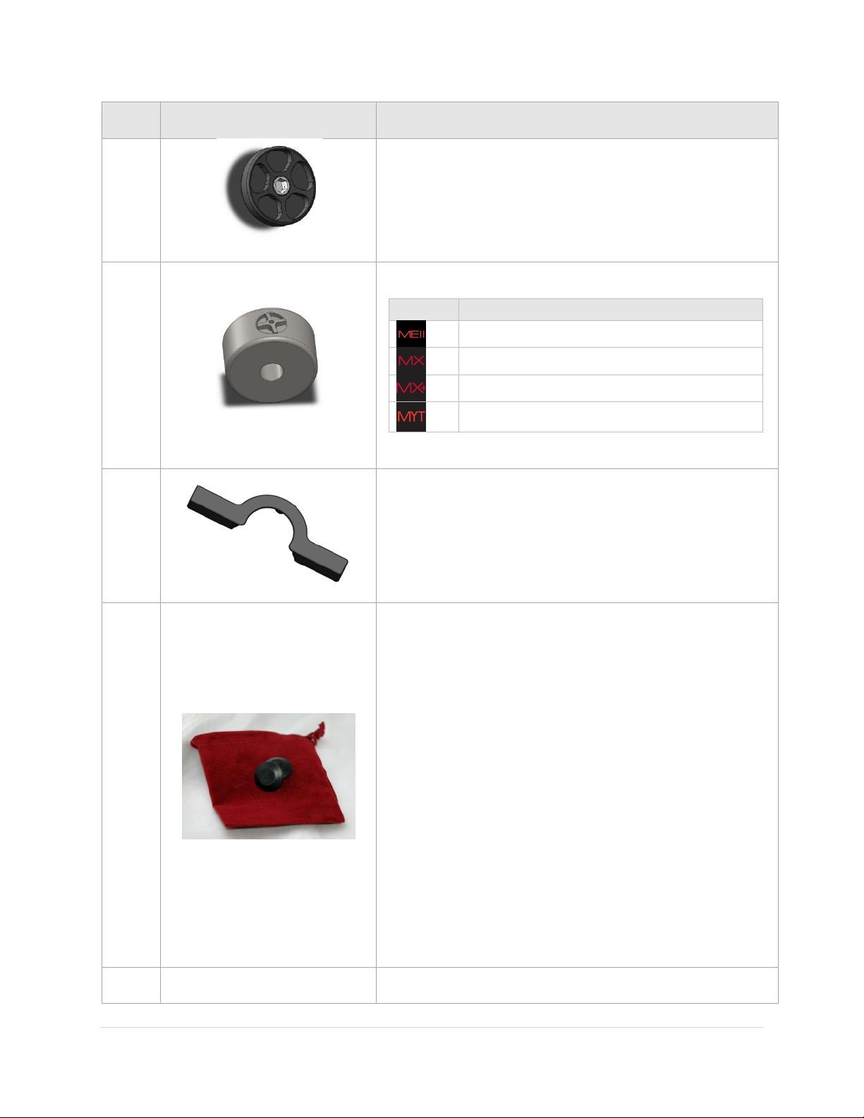
Paramount User Guide
Qty
Photo
Description
See
table
at
right.
Counterweights (page 99).
Model
Number of counterweights
Two 13.6 kg / 30 lb.
Two 9 kg / 20 lb.
Two 9 kg / 20 lb.
One 9 kg / 20 lb.
1
Paramount ME II (only) Altitude Adjuster Wrench (page 112).
1
Paramount ME II (only) Accessory Pouch
Use this pouch to store the following items:
Two (2) 3/8” shoulder bolt hole plugs for holding the two
(2) 5/16-in. x 2-1/4-in right ascension locking shoulder
bolts and two (2) declination locking shoulder bolts.
Four (4) Delrin washers. When locking the Paramount ME
II’s right axis (page 89), use two of these washers to
protect the surface of the mount from being marred by
the steel shoulder bolts.
Four (4) plastic plugs to cover the outer side of the right
ascension axis locking holes (page 89) and the declination
axis locking holes (page 108).
The pouch can be conveniently stowed behind the Altitude
Adjuster beneath the right ascension housing.
1
Cable tie to help route cables through the mount (Figure 8).
46 | P a g e

Paramount User Guide
Qty
Photo
Description
1
One (1) Paramount Software Suite thumb drive in jewel
box.
Before installing TheSkyX Professional Edition, please carefully read the Paramount Quick
Start Guide, which is shrink wrapped to the printed user guide inside the Accessories Box.
The PDF version can be downloaded from:
http://www.bisque.com/sc/media/p/77034.aspx
Locating Your Serial Numbers
The Paramount mount and the Paramount Software Suite serial number are printed on a card that is
attached to the altitude adjuster (Figure 13). Please retain this card for your permanent records.
Figure 13: The Paramount serial numbers are attached to the altitude adjuster.
47 | P a g e

Paramount User Guide
Your Paramount Software Suite serial number should be entered the first time TheSkyX
Professional Edition is launched. Doing so also automatically activates the Add Ons.
Registering the Paramount serial number, alone, does not register the software suite,
and is not sufficient to access software installers and updates. You must register both
the Paramount serial number and the Paramount software suite serial number.
Software Bisque does not automatically register serial numbers for you.
When you remove the packing tape on the Paramount shipping box, and lift the cardboard
flaps, please stop and carefully read the enclosed insert (shown in Figure 15) before
removing the mount from the box!
The insert describes very important basic mount features and the correct procedure to
prepare the mount for handling once it has been removed from the shipping box.
Paramount and Software Serial Number Registration
Please register the Paramount hardware and software serial numbers at:
http://www.bisque.com/register
Serial number registration gives your Software Bisque web account access to software installers, software
updates, control system firmware updates (page 151) and the latest MKS 5000 USB drivers (page 170).
Unpacking the Paramount
We trust you are excited to unpack and start using your Paramount as soon as possible. Please resist the
urge to simply remove everything from all the boxes, try to use the mount, and then consult the
documentation only after something goes wrong. Taking a few moments now to review and understand
the basic mount design will hopefully avoid potentially harmful accidents or damage to your mount.
Your Safety is Paramount
The Paramount is extremely rugged and designed to provide years of reliable service, but, like any
precision instrument, you must become familiar with certain basic features and operating procedures to
ensure proper use and your personal safety.
48 | P a g e

Paramount ME II Unpacking Insert
Paramount User Guide
Figure 14: Please carefully read the above flyer and the warning below before unpacking the Paramount ME II.
49 | P a g e

Paramount User Guide
Paramount MX Unpacking Insert
Figure 15: Please carefully read this flyer before unpacking the Paramount MX.
Please see the “RA Worm Block Switch” on page 73 for details about using the three position switch.
50 | P a g e
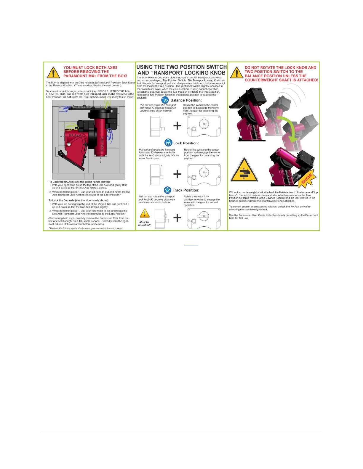
Paramount MX+ Unpacking Insert
Paramount User Guide
Figure 16: Please carefully read this flyer before unpacking the Paramount MX+.
Please see the “RA Worm Block Switch” on page 73 for details about using the two position switch.
51 | P a g e

Paramount User Guide
Figure 18: The three Paramount MYT right ascension axis locking positions.
Paramount MYT Unpacking Insert
Figure 17: Please carefully read this flyer before unpacking the Paramount MYT.
The Paramount MYT right ascension axis can be locked at one of three unique orientations (Figure 18).
1. The counterweight shaft is horizontal and the optical tube assembly side of the right ascension
axis is on the west side of the pier.
2. The counterweight is oriented vertically.
3. The counterweight shaft is horizontal and the optical tube assembly side of the right ascension
axis is on the east side of the pier.
52 | P a g e

Paramount User Guide
The declination axis can be locked at one of four unique positions, each 90 degrees apart (Figure 19).
Figure 19: The four Paramount MYT declination axis locking positions.
53 | P a g e

Paramount User Guide
Model
How to lock axis…
Install the locking shoulder bolts (page 89).
Rotate the right ascension axis three position switch to the Lock position.
Pull and rotate the transportation lock knob clockwise to the Lock position.
Pull and rotate the transportation lock knob clockwise to the Lock position.
1. When the declination axis is rotated fully clockwise, and the long axis of the Versa-Plate is parallel
to the wedge plates.
2. Starting from the orientation in Step 1, rotate the Versa-Plate 90 degrees counterclockwise.
3. Starting from the orientation in Step 1, rotate the Versa-Plate 180 degrees counterclockwise.
4. Starting from the orientation in Step 1, rotate the Versa-Plate 270 degrees counterclockwise.
Packing the Paramount for Transport
Always make sure to perform the following steps when packing up the Paramount for shipment or
transport.
1. Place the right ascension axis mechanical switch in the Balance position.
2. Rotate the right ascension axis so that the counterweight shaft is “down”.
3. Lock the right ascension axis so that it cannot rotate when the mount is lifted off the pier or tripod.
4. Carefully remove the payload from the Versa-Plate.
5. Carefully remove the counterweight safety knob.
6. Carefully remove the counterweights.
7. Carefully remove the counterweight shaft.
8. Rotate the Versa-Plate fully clockwise to the hard stop position. In this position, the Versa-Plate
is parallel to the sides of the mount so that the mount will lay flat in the box. Note the physical
hard stops prevent the declination axis from fully rotating 180 degrees. If the declination axis is
rotated fully counterclockwise, the edge of the Versa-Plate will not be parallel with the sides of
the mount, and will not lay flat in the box.
9. Remove the four Base Thrust Mounting Knobs.
10. Lift the mount off the pier or tripod and gently place it in the packing foam.
11. Unlock both axes before shipment. The shipping box may be dropped, or experience other
excessive forces during shipment. Allowing the axes to rotate helps prevent possible damage to
the locking mechanisms.
54 | P a g e

Paramount User Guide
Model
How to unlock axis…
Remove the locking shoulder bolts (page 89).
Rotate the right ascension axis and declination axis Three Position Switch to the
Balance position.
Pull and rotate the transportation lock knob clockwise to the Balance position and
make sure the worm and gear are disengaged by rotating both axis a few degrees
back and forth.
Pull and rotate the transportation lock knob clockwise to the Balance position and
make sure the worm and gear are disengaged by rotating both axis a few degrees
back and forth.
Paramount Components
Please carefully review and become familiar with each Paramount component before attempting to
operate the mount.
55 | P a g e

Paramount User Guide
Paramount ME II Front View
56 | P a g e
Figure 20: The front view of the Paramount ME II.

Paramount MX Front View
Paramount User Guide
Figure 21: The front view of the Paramount MX.
57 | P a g e

Paramount User Guide
Paramount MX+ Front View
58 | P a g e
Figure 22: The front view of the Paramount MX+

Paramount MYT Front View
Always keep hands and fingers away from the right
ascension axis worm block cover!
A “pinch point” is created as the declination axis rotates past
the right ascension axis worm block cover.
Paramount User Guide
Figure 23: The front view of the Paramount MYT.
RA Worm Block Cover
59 | P a g e

Paramount User Guide
Figure 24: Caution: Always keep hands clear of this area!
Payload Mounting Plate (Versa-Plate)
The Paramount Versa-Plate provides a stable mounting platform to carry a variety of astronomical
equipment. The optical tube assembly can be attached using the integrated Losmandy and Celestron
dovetail rail-compatible dovetail, a telescope cradle, or telescope mounting rings. The Instrument Panel
(page 67) mounted to the bottom rear of the Versa-Plate places power ports, two USB 2.0 ports, and
custom through the mount cables near the camera-end of the telescope, right where they’re needed.
60 | P a g e

Paramount User Guide
Figure 25: The Paramount ME II Versa-Plate technical specifications.
Figure 26: The Paramount MX and MX+ Versa-Plate technical specifications.
61 | P a g e
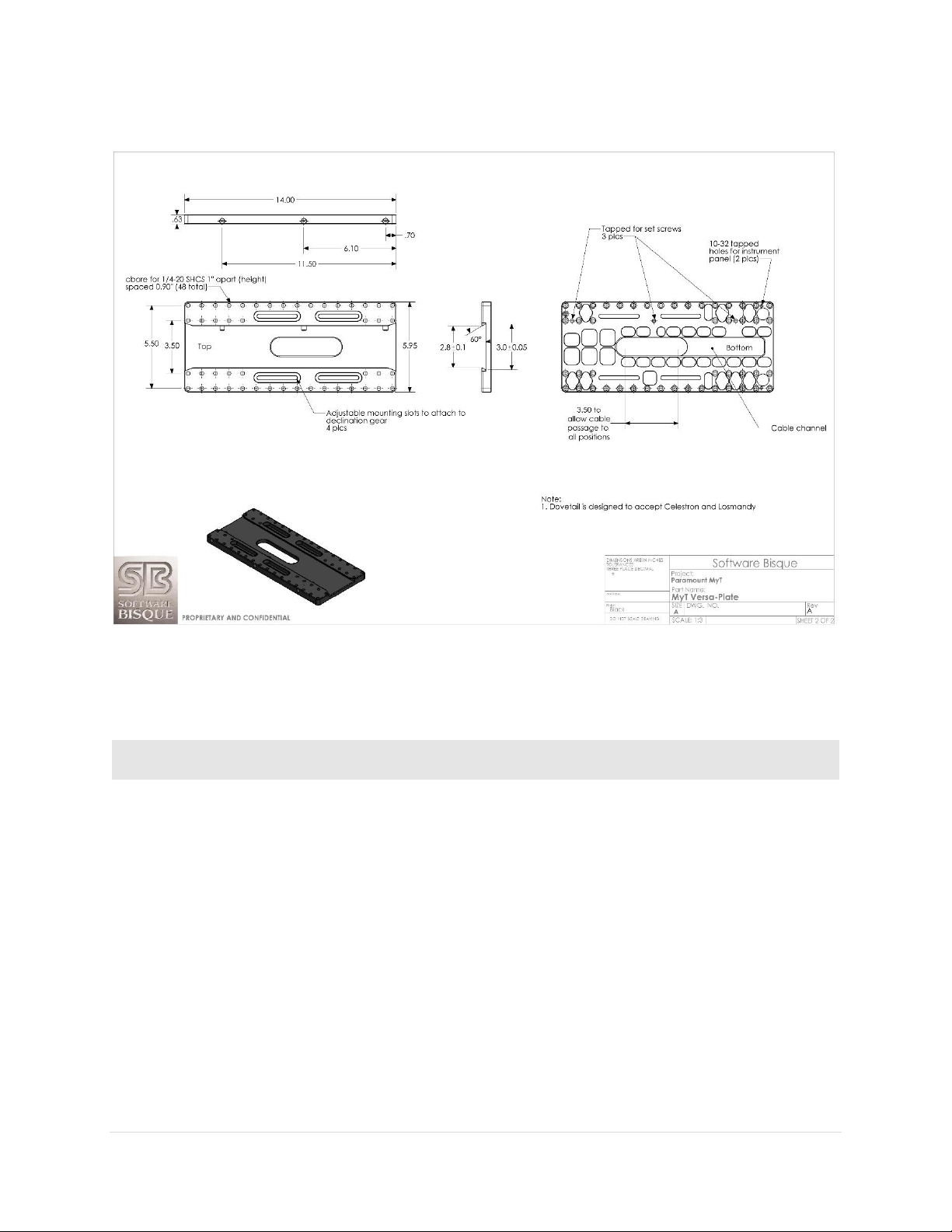
Paramount User Guide
OTA Mounting
Advantages
Disadvantages
Losmandycompatible
Dovetail
Mounting the OTA to the Versa-Plate is
relatively fast and easy.
Hardware is available, or integrated into
telescopes from several different
manufacturers, including:
o ADM Accessories
o Celestron International
o Losmandy Astronomical
Products
o Meade Instruments
o Officina Stellare
Dovetails are not always
rigidly mounted to the
OTA itself. This can
introduce flexures that
affect overall pointing
accuracy and
repeatability.
Figure 27: The Paramount MYT Versa-Plate technical specifications.
The table below lists the most common hardware used to mount telescopes (or optical tube assemblies)
and the advantages and disadvantages of each system.
62 | P a g e

Paramount User Guide
OTA Mounting
Advantages
Disadvantages
Parallax
Instruments OTA
Tube Rings
Extremely rigid mount-to-telescope
attachment.
Allows multiple optics to be rigidly
mounted.
Repeatable all sky pointing.
Hardware is usually
more expensive.
Model
How to unlock axis…
Install the right ascension locking bolts and rotate the right
ascension Two Position Switch to the Balance position (page 89).
Rotate the right ascension axis Three Position Switch to the Lock
position (page 73).
Rotate the right ascension axis Two Position Switch to the
Balance position (page 73) and pull and rotate the Transport Lock
Knob to the Lock position (page 73).
Rotate the right ascension axis Two Position Switch to the
Balance position (page 73) and pull and rotate the Transport Lock
Knob to the Lock position (page 73).
Paramount Versa-Plate Knobs
The Versa-Plate Knobs (three on the Paramount MX, Paramount MX+ and Paramount MYT, four on the
standard Paramount ME II; up to six with the optional Large Dovetail Accessory Rail) are designed to
securely captivate a male Losmandy-compatible dovetail. Rotating the knob clockwise advances an
angled brass plunger on the inside of the dovetail. The angled brass plunger wedges the male dovetail to
the opposite side of the female dovetail to prevent any slippage or rocking of the payload, regardless of
the mount’s orientation.
To mount an OTA with a male dovetail to the Versa-Plate:
1. With the counterweight shaft oriented vertically, lock the right ascension axis in place.
2. Carefully slide the male dovetail on the OTA into the Versa-Plate’s dovetail until the OTA is
approximately balanced in the declination axis.
Figure 28: The brass plunger compresses the male dovetail (from left to right in the above diagram).
63 | P a g e
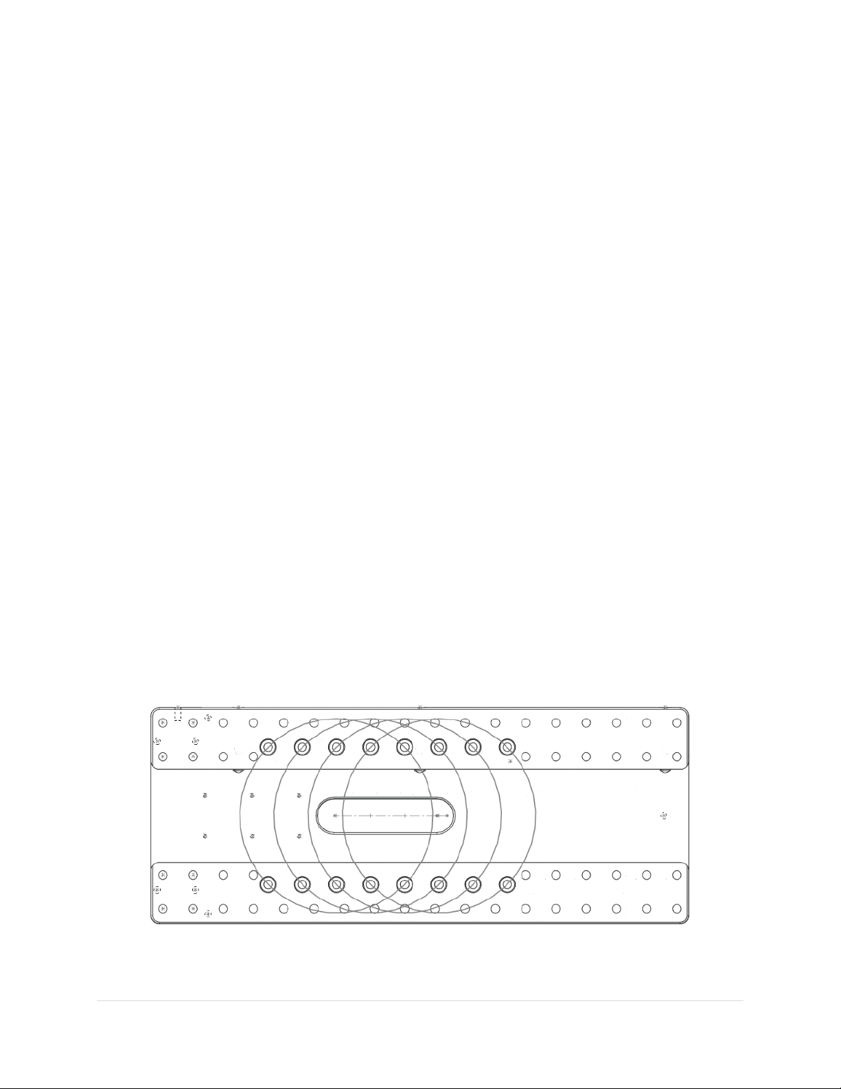
Paramount User Guide
3. Hand tighten each Versa-Plate knob until the brass plungers securely hold the dovetail in place.
While tightening the knobs, push slightly on the OTA in the same direction as the advancing brass
plungers to make sure the dovetail plate is securely compressed against opposite side of the
dovetail wedge (Figure 28). Also ensure that the male dovetail plate is securely captivated by at
least two of the Versa-Plate Knobs before letting go of the OTA or testing declination axis balance.
Securing a heavy or expensive payload with one knob is not sufficient. The length of the male
dovetail varies by manufacturer. For best results and when the length of the male dovetail
permits, always tighten all three knobs to the hold it securely in place.
4. Test the declination axis balance, then make adjustments to the position of the payload as
needed.
5. After the payload in the declination axis is balanced and the knobs are hand tightened, definitively
secure each knob by inserting a 1/4-in hex wrench and tighten it an additional one-quarter turn
only. Do not over tighten these knobs or the internal threads can be damaged. Note that when
two or three of the knobs are “hand tightened”, the dovetail will not slide. The final 1/4 turn with
the hex wrench ensures that your heavy and expensive payload is mounted securely and will not
move when the mount slews.
Versa-Plate Mounting Positions
The Paramount MX, MX+, ME II and MYT Versa-Plate can be mounted to the top of the declination axis in
four different positions to move the balance point of different payloads. The gray circles in Figure 29
represent the top of the declination axis at each mounting position.
If your payload is “camera-end heavy,” mount the Versa-Plate at the forward most position so that the
payload can be more easily balanced. Remove the six 1-inch socket head cap screws (SHCS) using a 3/16in hex wrench, then adjust the position of the Versa-Plate accordingly. The mounting position depends
on your equipment, so there may be a bit of trial and error to find the optimal spot. The four SHCS should
be tightened snugly so that the Versa-Plate cannot wiggle or shift when carrying the payload, but not too
tight.
Figure 29: Machined circles mark the four mounting positions on the Paramount MX and Paramuont MX+ Versa-Plate. (The
Instrument Panel end is to the left.) The Paramount ME II’s Versa-Plate has two mounting positions.
64 | P a g e

Paramount User Guide
The Instrument Panel is attached to the bottom of the Versa-Plate. Typically, you will want
to mount the optical tube assembly to the Versa-Plate so that the eyepiece or camera end
is as close to the Instrument Panel as possible. Doing so offers the shortest cable route
between powered accessories that are mounted to the draw tube and the power ports on
the Instrument Panel.
Figure 30: The Versa-Plate mounting slots on the Paramount MYT allow the payload to be adjusted to achieve balance in
declination.
The Paramount MYT Versa-Plate has four slots that can be used to adjust the balance point of the payload
in declination. To do so, loosen the four ¼-20 SHCS screws using a 3/16-in. hex wrench, then slide the
Versa-Plate to the desired position. Once balance has been achieved, snugly tighten each screw enough
so that the Versa-Plate does not rotate or shift during mount slews, but not so tight as to deform the
washers.
Standard versus Wide Mounting Versa-Plate Orientation
The Paramount is shipped with the Versa-Plate in the standard orientation. The Versa-Plate can also be
mounted at 90 degrees from the standard orientation, offering a wider mounting area to accommodate
multiple optical tube assemblies.
65 | P a g e

Paramount User Guide
The standard Versa-Plate mounting configuration works well for Schmidt-Cassegrain,
Ritchie-Chretien, and refracting telescopes where the “business end” naturally places
equipment near the Instrument Panel.
For Newtonian telescopes and other optical designs, where the camera and other
accessories are located toward the “front” of the telescope, the Versa-Plate can be rotated
180 degrees so that the devices are closer to the Instrument Panel.
Figure 31: The standard (left) and wide (right) Versa-Plate mounting orientations for the Paramount MX.
Figure 31 shows one standard and one wide orientation of the Versa-Plate, relative to the top of the
Paramount MX declination axis. For each orientation, the black arrow shows the direction incoming light
passes through the optical tube assembly when it is mounted to the Versa-Plate.
When mounting the Versa-Plate on the Paramount MX, pay very close attention to the mounting holes
on the top of the declination axis. The three circled holes in Figure 31 form a triangle that must point
toward the stars, or, in the opposite direction of the OTA’s incoming light.
Notice that for the both the standard and wide orientations, there are symmetrical mounting holes on
the top of the declination axis that allow the Versa-Plate to be attached 180 degrees apart; either one can
be used, depending on your needs. However, when mounting the OTA, make sure to maintain the relative
orientation between the top of the declination axis and the direction of incoming light described above.
Otherwise, the telescope will not point in the correct direction.
To help make sure the Versa-Plate is mounted properly, early model Paramount mounts had an arrow
machined into the top of the declination axis that represented the direction of incoming light. The top of
the declination axis on later model Paramount ME II, Paramount MX+ mounts, and all Paramount MYT
mounts have an arrow and star machined into the top of the declination axis (Figure 31). For these
66 | P a g e

Paramount User Guide
If the optical tube assembly is attached to the Versa-Plate such that the OTA’s
direction of incoming light does not align with the direction of incoming light for
the declination axis, homing the mount will result in the optical tube pointing
somewhere besides hour angle 2 and declination 0. Remove both the OTA and
the Versa-Plate to ensure both are mounted properly.
Mounting the Paramount MYT’s Versa-Plate in the wide orientation reduces the
cross-sectional area for cabling to pass through on the top of the declination axis
by about one-third. There is still sufficient space for the standard cables and a
few custom cables, be aware that there is less “wiggle room” compared to the
standard orientation.
mounts, the machined arrow pointing to a star means the optical tube should be mounted such that the
light gathering end of the telescope should be closest to the machined star.
To change the orientation of the Versa-Plate from the standard to the wide configuration:
1. Remove the six 1-inch ¼-20 3/16 socket head cap screws on the top of the Versa-Plate.
2. Rotate the Versa-Plate 90 degrees. The top of the declination axis has “indentations” to
accommodate the Instrument Panel-specific and custom through the mount cabling.
3. Align the mounting holes on the Versa-Plate with the mounting holes at the top of the declination
axis and replace four of the six screws. Only four socket head cap screws are used in the wide
orientation.
4. When mounting the OTA, make sure that the direction of incoming light for the OTA corresponds
with the required direction of incoming light for the declination axis as described above.
A simple litmus test to make sure the OTA is mounted properly is to home the mount. Once the homing
process is completed, if the telescope is not pointing at hour angle 2 and declination 0, the OTA mounted
incorrectly. To correct this situation,
1. Remove both the OTA and the Versa-Plate.
2. Double-check the orientation of the Versa-Plate with the top of the declination axis.
3. Double-check the direction of incoming light of the OTA with the orientation of the three holes
on the top of the declination axis (Paramount MX) or the machined arrow on the top of the
declination axis (Paramount ME II and Paramount MX+).
4. Rotate the OTA and/or Versa-Plate and remount them so that these three components are
properly aligned. If necessary, home the mount with no payload and no Versa-Plate attached,
then appropriately reattach both.
Versa-Plate Cable Spacers (Paramount ME II only, Optional)
Software Bisque offers optional spacers that can be used when the Paramount ME II Versa-Plate is
mounted in the wide orientation. When mounted to the top of the declination axis, the spacers create a
67 | P a g e

Paramount User Guide
channel through which instrument cabling can be passed. Spacers can also be used in the standard
position allowing more “clearance” for instrument cabling.
Large Dovetail Accessory Rail (Paramount ME II only, Optional)
The Paramount ME II can accept optical tube assemblies with a PlaneWave Instruments dovetail mounting
plate using the optional Large Dovetail Accessory Rails. Four “rails” and the rotating safety knob mount
directly to the existing Versa-Plate and offer six mounting knobs to securely attach and carry 20-inch class
optical tubes. The safety knob allows a heavy optical tube assembly to be mounted by placing one edge
of the male side of the dovetail into place, then rotating the telescope to meet the other side, rather than
having to slide the entire payload along the length of the dovetail. Once the OTA is in place, rotate the
safety knob to temporarily captivate the OTA and then proceed to tighten each Versa-Plate knob until the
OTA is secure.
Instrument Panel
Figure 32: The Instrument Panel housing is mounted to the bottom of the Versa-Plate.
Figure 33: Photograph of the Instrument Panel.
Instrument Panel Components
The Instrument Panel provides two USB 2.0 ports, a guider port, a focuser for pulse focuser control and
ports that can be used to supply power to your devices.
68 | P a g e

Paramount User Guide
The Paramount External power ports and through the mount cabling
is intended to be used with direct current (DC) power sources only.
Never attempt to power devices through the mount with an
alternating current (AC) power source.
The External Power connectors on the Instrument Panel and on the Electronics Box do not
supply power nor do they have anything to do with the Paramount MX or Paramount MX+
power supply.
These connectors act as a conduit to route an external power source that is connected to
the Power In connector located Electronics Box to the Power Out connector on the
Instrument Panel.
Powering Devices (Power Out)
The Instrument Panel port labeled Power Out is the output port for the mount’s built-in through the mount
power cabling. The input port for the through the mount cabling is labeled Power In on the Electronics
Box (page 78).
These ports are designed to satisfy the power requirements for a variety of DC-powered astronomical
devices, including dew heaters, video cameras, and other instruments.
The “stock” through the mount cabling for this connector uses 18-gauge AWG wires to carry relatively
heavy DC loads and the 4-pin Kycon KPPX-4p series connectors (Mouser part number 806-KPPX-4P) are
rated to carry a maximum of 20 volts at 7.5 amps.
Software Bisque offers cable sets that can be used to route power through the mount for many model
cameras, as well as a generic “pig tail” cable set if you want to supply power to different device. See
“Appendix C: External Power Cable Sets” on page 178 for these cable specifications.
If you plan on making your power own cables, the KPPX series snap and lock power connectors have many
advantages, including:
Self-locking
Small footprint
Inexpensive
Readily available
Rated for relatively heavy power loads
Available in board mount or straight-through configurations
Search for “KPPX video assembly” on the Kycon web site for printed and video-based assembly
instructions.
69 | P a g e

Paramount User Guide
Both USB ports on the Instrument Panel are powered by the Paramount control system.
If a USB camera plugged into one of these ports and the mount’s power is turned off, the
USB camera will no longer be able to communicate with the computer that is connected to
the mini USB port on the Electronics Box.
USB Ports (USB A and USB B)
These two USB ports are part of an integrated USB hub on the MKS 5000 electronics board. The
Instrument Panel’s two USB ports can connect any two USB 2.0 devices to a computer’s USB port.
To allow USB communication between these ports and the computer, plug the square end of the miniUSB cable to the Electronics Box’s mini-USB port and the flat end into your computer’s USB port. Next,
plug the rectangular end of the device’s USB cable into either USB A or USB B and power on the mount.
Guider Port (Guider)
This RJ12 port is based on pin outs from the standard SBIG guider connector that is used by virtually every
astronomical camera. See the “Guide Port” section of the SG-4 Autoguider Operating Manual for the
SBIG autoguider port specifications.
Figure 34: Diagram showing the pin outs for the guider cable and the camera and guider port.
Plug one end of the standard guider cable into the camera’s guider port, and the other end into the
Instrument Panel’s Guider port.
70 | P a g e

Paramount User Guide
Autoguiding, which involves monitoring the position of a guide star and adjusting the
mount’s position as the star moves, has traditionally be performed using a guider cable
attached to the camera’s guider port and the telescope’s guider port as described above.
Software Bisque’s DirectGuide feature eliminates “relay based” autoguiding. A Paramount
mount, coupled with TheSkyX Professional Edition and the Camera Add On configured to
autoguide using DirectGuide makes guider ports obsolete. DirectGuide details can be found
in TheSkyX Professional Edition User Guide.
Attempting to power a device through this port that draws more than 5W
(5V at 1A max.) will cause the MKS 5000 control system to emit successive
beeps, indicating an “error condition.”
The total power supplied to both the 5V and 12V ports is 12W (+12V DC at
1A max.). When using both ports to power devices, make sure that the
combined power required by each device does not 12W.
If this occurs, the device should be powered using the OEM, or other sufficiently
rated power source.
Focuser Port (Focus)
Use this port to connect your pulse focuser to the mount so that TheSkyX Professional Edition or other
software (using TheSkyX Professional Edition as a server) can be used to “remotely” adjust the focuser’s
position.
Plug the pulse focuser into this port, establish communication with the Paramount, then use the Focus
Controls on TheSkyX Professional Edition’s Telescope window to adjust focus.
5 Volt Power Jack (5V)
The Instrument Panel port labeled 5V can supply power for devices that require up to 5W (+5V DC at 1A
max.).
Power to this unfused 2.1 mm female port is supplied by the MKS 5000 control system, so the mount must
be plugged in and turned on for it to be operational. Compatible 2.1 mm male DC power plugs include:
Mouser part number 1710-0721 (no locking collar)
Mouser part number 171-7391 (locking collar)
12 Volt Power Jack (12V)
1A max.).
Power to this unfused 2.1 mm female port is supplied by the MKS 5000 control system, so the mount must
be plugged in and turned on for it to be operational. Compatible 2.1 mm male DC power plugs include:
The Instrument Panel port labeled 12V can provide power to devices that require up to 12W (+12V DC at
71 | P a g e

Paramount User Guide
Attempting to power a device through this port that draws more than 12W
(12V at 1A max.) will cause the MKS 5000 control system to emit successive
beeps, indicating an “error condition.”
The total power supplied to both the 5V and 12V ports is 12W (+12V DC at
1A max.). When using both ports to power devices, make sure that the
combined power required by each device does not 12W.
If this occurs, the device should be powered using the OEM, or other sufficiently
rated power source.
Mouser part number 1710-0721 (no locking collar)
Mouser part number 171-7391 (locking collar)
RA Worm Block Cover
The RA Worm Block Cover incorporates the following features:
Protects the internal right ascension worm block components from dust and debris.
Provides a convenient handle to grasp when lifting the mount.
Houses the right ascension axis Three Position Switch (page 73).
RA Cable Conduit
This access hole in the right ascension shaft allows custom cables to be passed through the mount. See
“Through the Mount Cabling” on page 35 for more information.
This access hole is dome-shaped to serve as an integrated carrying handle and is covered by the RA Gear
Cover.
RA Gear Cover (ME II Only)
The RA Gear Cover provides an access hole for through the mount cables.
Dec Cable Conduit
This access hole in the declination shaft allows custom cables to be passed through the mount. See
“Through the Mount Cabling” on page 35 for more information.
Right Ascension Carrying Handle
Use the integrated carrying handle to lift the mount. On the Paramount MX, place the Three Position
Switch in the Lock position before lifting the mount. The Paramount ME II’s RA Cable Conduit access hole
is dome-shaped and serves as the integrated carrying handle (remove the RA Gear Cover to access it). The
Paramount MX+ has no integrated carrying handles but underneath the electronics box can serve as an
aid when carrying the mount.
72 | P a g e

Paramount User Guide
RA Worm Block Switch
The Paramount’s RA and Dec Axis have an arrow-shaped knob as part of a rotatable, mechanical switch.
(The Paramount ME II and Paramount MX+ switch has two positions and is referred to as the Two Position
Switch. The Paramount MX switch has three positions and is referred to as the Three Position Switch).
This switch can be rotated to one of two or three positions and each position places the mount in a
different operational state as described in the table below.
Figure 35: The Paramount ME II Two Position Switch.
Figure 36: The Paramount MX Three Position Switch.
73 | P a g e

Paramount User Guide
Model
Mechanical Switches
When the Two Position Switch (Figure 35) is in the Balance position, the worm and gear are
separated so the axis can rotate freely. When the switch is rotated to point at the star, the
mount is ready for normal operation.
Separate locking bolts must be installed lock the axis in place. See “Right Ascension Axis
Locking Hole (Paramount ME II Only)” on page 89 and “Declination Axis Locking Hole
(Paramount ME II Only)” on page 108 for details about locking the Paramount ME II axes.
Figure 37: The Paramount MX+ Two Position Switch and Transport Lock Knob.
Figure 38: The Paramount MyT Two Position Switch.
74 | P a g e

Paramount User Guide
Model
Mechanical Switches
The balance, star and lock symbols shown are etched into the top of the cover of the
Paramount MX, where they are most visible when setting up the mount (Figure 36).
The Balance, Star, and Lock positions (Figure 37) are etched on the front of the Paramount
MX+ worm block covers. The arrow-shaped Two Position Switch is used to balance and
track; the circular Transport Lock Knob is used to lock the axis during transport, or free the
axis during normal use.
Notes:
The Transport Lock Knob is slightly recessed in the lock position.
The Transport Lock Knob should always be rotated clockwise when locking or
unlocking the axis.
When the Two Position Switch (Figure 38) is in the Balance position, the worm and gear are
separated, so the axis can rotate freely. When the switch is rotated to point at the star
(Track position), and the Transport Lock Knob is in the unlock position, the mount is ready
for normal operation.
Notes:
The Transport Lock Knob is slightly recessed in the lock position.
The Transport Lock Knob should always be rotated clockwise when locking or
unlocking the axis.
ADJUSTING THE PARAMOUNT’S MECHANICAL SWITCHES ALWAYS REQUIRES
BOTH HANDS!
Rotating the Two or Three Position Switch for both the RA axis and the Dec axis
requires the use of both hands to prevent sudden or unexpected rotation of the
mount.
Before rotating the Dec Axis Two or Three Position Switch with your right
hand, firmly grasp the Versa-Plate with your left hand to prevent sudden
rotation of this axis from an unbalanced payload.
Before rotating the RA Axis Two or Three Position Switch with your right
hand, firmly grasp the Counterweight Shaft with your left hand to
prevent sudden rotation of this axis from an unbalanced payload.
When the switch is rotated to, or passes through the Balance Position, the axis
will rotate freely. Unexpected rotation of either axis due to an unbalanced
payload can cause personal injury or serious damage to the mount!
Always use extreme caution and, please, always use BOTH HANDS!
75 | P a g e

Paramount User Guide
Track Position: Rotate the arrow on the switch fully counterclockwise to
engage the worm with the gear. This position is used during normal mount
operation.
Balance Position: Rotate the arrow on the switch to the center position to
disengage the worm from the gear so that the axis rotates freely.
Balancing either the right ascension or declination axis of the
Paramount is always a two-handed operation! Please
carefully read the document shown in Figure 15 for details
about where to grasp each axis before placing the Three
Position Switch in the Balance Position.
This position is for balancing the payload and is the recommended position to
place the switch after the mount has been placed inside the shipping container
box and while the mount is being transported. If the mount is subjected to a
severe impact during shipping, both axes will rotate freely. Unrestricted
motion in each axis can help minimize damage to the worms and gears.
The Paramount must always be homed after balancing either
axis! Otherwise, the mount will be “lost in space” and
potentially slew beyond the software slew limits.
Lock Position (Paramount MX only): Rotate the Three Position switch fully
clockwise to separate the worm from the gear and lock the axis in place.
Always lock both axes before lifting the mount.
An axis can be locked to any position, at 5 degree increments. Note that
physically rotating the switch to the Lock Position inserts an internal locking
shaft into one of 72 locking holes that are machined into the internal gear. You
will usually need to wiggle the axis a few degrees back and forth in order to
align the locking shaft with one of the locking holes. When the shaft enters the
hole, the entire Three Position Switch will drop slightly into worm gear cover.
Once locked, the axis can no longer rotate.
Rotating the switch away from the Lock Position causes the locking shaft to be
removed from locking hole and the axis will rotate freely. Note that the entire
switch itself will rise slightly out of the worm block cover as a result.
Unlock Position (Paramount MX+ and MyT): Pull out and rotate the
transportation lock knob 90 degrees clockwise to lock/unlock the axis. While
this knob can be rotated in either direction, always rotate it clockwise as
counterclockwise rotation may cause the knob head to become loose. Always
lock both axes before lifting the mount.
76 | P a g e

Paramount User Guide
Each axis can be locked at any position, in five degree increments. Note that
physically rotating the switch to the Lock Position inserts an internal locking
shaft into one of seventy two locking holes that are machined into the internal
gear. You will usually need to wiggle the axis a few degrees back and forth in
order to align the locking shaft with one of the locking holes. When the shaft
enters the locking hole, the entire transport lock knob will drop slightly into
worm gear cover. The axis will not rotate when the knob is in the lock position,
even if the two position switch is in the Track position.
Pulling out and rotating the knob 90 degrees allows the axis to rotate freely.
Note that the entire knob will rise slightly out of the worm block cover when in
the unlocked position.
RA Spring Plunger and Cam Stop Access Hole (Paramount ME II and MX+ Only)
This hole provides access to the spring plunger and cam stop adjustment. See the Paramount Cam Stop
Adjustment Instructions document here:
http://www.bisque.com/sc/media/p/75503.aspx for details.
RA Encoder Cover (Paramount ME II Only)
This cover provides access to the absolute encoder module and is reserved for future use.
RA Assembly
The RA Assembly houses an internal shaft that can be used to snake additional cables through the mount
and allows light to pass through the mount for the polar alignment telescope.
Electronics Box
The Electronics Box includes the mount power switch, USB 2.0 cable input, status lights, ports that can be
used to run power through the mount to the Instrument Panel, a hardware park port and an expansion
slot access panel for the WiSky Wi-Fi and absolute encoder module.
77 | P a g e
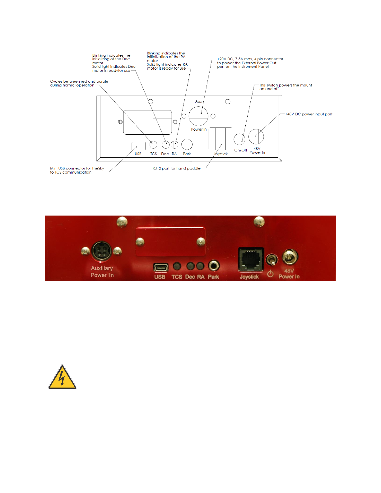
Paramount User Guide
The Paramount External power ports and through the mount cabling
is intended to be used with direct current (DC) power sources only.
Never attempt to power devices through the mount with an
alternating current (AC) power source.
Figure 39: Technical drawing of the Paramount MX and Paramount MX+ Electronics Box labeling each component.
Figure 40: Photograph of the Paramount ME II Electronics Box.
Electronics Box Components
External Power (Power In)
This 4-pin DC power connector can be used to run up to 20V at up to 7.5 amps DC maximum power
through the mount to the Instrument Panel. See “Powering Devices (Power Out)” on page 69 for
specifications for this connector and the internal cabling.
See page 178 for the pin out specifications and connector part numbers.
78 | P a g e
Paramount User Guide
The External Power connectors on the Instrument Panel and on the Electronics Box do
not supply power nor do they have anything to do with the Paramount power supply.
These connectors act as a conduit to route an external DC power source that is connected
to External Power connector located in the Electronics Box to the External Power
connector in the Instrument Panel.
Do not plug the Paramount ME II power supply into this port! See “Power Input (48V
Power In)” on page 80 for instructions on how to supply power the Paramount ME II.
Do not attempt to supply voltage to this port! Doing so can damage to the MKS 5000
control system and immediately voids the warranty.
Mini USB Port (USB)
The mini USB 2.0 port accepts the square end of the standard mini USB cable connector (supplied with
the mount). Plug the rectangular end of the USB cable into the computer’s USB port.
TCS Status LED (TCS)
The Telescope Control System (TCS) status light emitting diode (LED) “pulsates” from bright to faint to
provide visual confirmation that the control system is operating normally. If this LED is not illuminated
after turning the mount on, there may be a problem with the Bisque TCS control system. Please contact
Software Bisque (page 15) for further troubleshooting advice.
Right Ascension and Declination LEDs (Dec and RA)
The right ascension and declination LEDs show the status of the DC-servo motors. The LEDs blink while
the motors are being initialized. When the LEDs shine steadily, the motor is operating normally and ready
for use. If either LED is not illuminated, motor initialization failed. An unbalanced payload, uncentered
joystick, or depressed joystick button can cause motor initialization failure. Turn the power off, make sure
the mount payload is properly balanced, the joystick on the hand controller is centered, and the joystick
button is not pressed before repowering the mount to see if the behavior persists.
Hardware Parking (Park)
Reserved for future use. This port may offer the ability to “hardware park” the Paramount by supplying
an external voltage to the port. This capability offers an alternative to parking the mount using TheSkyX
Professional Edition and can be crucial as a backup parking method when operating the mount remotely.
Hand Controller or Joystick Port (Joystick)
Plug the RJ12 connector on the Paramount hand controller or the Paramount ME joystick to manually
home and slew the mount. See page 108 for details about this component.
79 | P a g e

Paramount User Guide
Model
Connecting PSU to 48V Power In Port
Connecting the PSU to
External Power
1. Plug the 4-pin locking male Kycon connector on the PSU into
the female Kycon connector on the Power Supply Extension
Cable.
Figure 41: Paramount ME II PSU plugs into the Power Supply Extension Cable.
Do not attempt to plug the 4-pin Kycon connector on the PSU
into the Electronics Box port labeled Power In.
2. Plug the male Kobiconn DC power plug on the Power Supply
Extension Cable into the port labeled 48 V Power on the
Electronics Box.
Plug the female end of
the Power Cable for the
Power Supply Unit
(page 45) into the PSU’s
power input. Plug the
male end into an
external power supply
(electrical grid, battery
or suitable other power
source).
Plug the male Kobiconn DC power plug on the Power Supply
Extension Cable into the port labeled 48V Power on the
Electronics Box.
Plug the female end of
the Power Cable for
the Power Supply Unit
(page 45) into the
PSU’s power input.
Plug the male end into
an external power
supply.
Mount Power Switch (On/Off)
This switch turns the mount on (up position) and off (down position).
Power Input (48V Power In)
This port is used to supply power to the mount’s control system. The Electronics Box’s female 48V Power
In port accepts a 2.5 mm Kobiconn DC power plug with a locking collar (Mouser Electronics part number:
171-7395, http://www.mouser.com).
The Paramount ME II, Paramount MX, Paramount MX+ and Paramount MYT PSUs use tip positive plugs.
See “Power Supply Unit" on page 112 for more information.
Plugging Power Supply Unit into the Electronics Box
The Paramount MX PSU can be plugged directly into the 48V Power In port on the Electronics Box; the
Paramount ME II and Paramount MX+ requires an additional power extension cable. The table below
describes how to physically connect the PSU of each model from the external power source to the 48V
Power In port (page 80) on the Electronics Box.
80 | P a g e

Paramount User Guide
Expansion Slot Cover
The removable cover on the front of the Electronics Box provides access to a plug in “expansion slot” on
the MKS 5000 electronics board. This expansion slot may be used to provide future control system
enhancements. For now, there is no reason to remove this cover.
Polar Alignment Scope Mounting
The Paramount ME II, Paramount MX and Paramount MX+ can be fitted with an optional polar alignment
scope to optically align the mount’s polar axis with the celestial pole. The Paramount Polar Alignment
Scope includes the optics, a reticle illuminator, an extension tube, a threaded machined aluminum cover
that protects the scope during transit and a mounting bracket that provides space for custom through the
mount cabling to exit the mount.
Figure 42: Polar Alignment Scope and mounting hardware.
Download the PDF document named “Paramount Polar Alignment Scope Installation and Use” from the
Software Bisque Downloads page for more information:
http://www.bisque.com/sc/media/p/58136.aspx
Type the URL below into your web browser’s Address bar to purchase the Paramount Polar Scope:
http://www.bisque.com/sc/shops/store/MXPolarScope.aspx
Polar Axis Adjustments
A common problem with many commercial mounts when making polar alignment adjustments is that
changes to the position of the altitude axis also changes the position of the azimuth axis, and vice-versa.
In other words, the basic mechanical design is flawed in that it prevents independent motion in azimuth
and altitude. This makes precise polar alignment more difficult than it should be.
81 | P a g e

Paramount User Guide
The Paramount base consists of an outer, fixed plate that is mounted to the pier, and an inner rotating
plate on which the mount sits. Adjustments in azimuth are achieved by rotating the Azimuth Adjustment
Knobs at the front of the mount (Figure 43). For a level mount, rotation of this plate does not affect the
altitude of the polar axis.
The altitude axis is held in place using a separate mechanical system that includes the Altitude Adjuster
Thrust Knobs (Figure 60) and the Altitude Adjuster (Figure 45). For a level mount, adjustments in altitude
will not change the azimuth of the polar axis.
Azimuth Adjuster Knobs
The base of the Paramount incorporates a circular plate inside the mount’s rectangular base, and allows
the mount to rotate about a vertical axis through the center of the mount. This rotation permits the
azimuth of the polar axis to be changed when aligning the mount to the celestial pole. The Azimuth
Adjustment Knobs push against a bar that is mounted to the circular plate and provide the means to rotate
the plate, even when the mount if fully loaded.
The Azimuth Adjustment Knobs work in opposition – one must be loosened before the other can be
tightened. The knob that is tightened rotates the azimuth axis; the knob that is loosened provides
“clearance” for the axis to rotate.
Provided the opposite knob is sufficiently loose, the azimuth axis can be rotated by tightening the opposite
knob, without applying excessive force. Note that a fully-loaded mount may make rotating the base plate,
and the knobs, more difficult. If necessary, insert a 5/32 hex wrench into the center of the adjustment
knob to assist rotation. For really heavy loads,
Tightening the right knob moves azimuth east.
Tightening the left knob moves azimuth west.
Before making any adjustments to the azimuth of the polar axis:
Make sure the rotating plate is close to its center position so there is a maximum amount of
rotation in both directions.
Rotate both knobs counterclockwise until both are just tight. This effectively squeezes the
rotating bar and serves as a good zero point. To avoid deforming the rotating bar, do not over
tighten the knobs.
When making adjustments based on the advice given in the TPoint Add On Polar Alignment
Report, first loosen the knob on the opposite side of the direction of rotation the suggested
number of tics, then tighten the other knob until it is “just tight” again.
82 | P a g e

Paramount User Guide
The azimuth axis polar axis adjustment range is plus or minus seven (7) degrees from center
position. To be safe, make sure to orient your permanent pier within three (3) degrees (or
so) of the celestial pole so that polar alignment can be achieved without having to rotate
the permanently mounted pier itself.
Software Bisque Permanent piers have slotted mounting holes that provide
additional azimuth rotation (plus or minus five degrees from the center position).
The Software Bisque Pyramid Portable Pier and the Might Tripod allow unlimited
rotation in azimuth, so the mount’s initial orientation does not matter.
Figure 43: Rotate the Azimuth Adjuster Knobs to adjust the azimuth axis (Paramount MX pictured above).
Azimuth Vernier Scale
Both Azimuth Adjuster Knobs include Vernier scales that can be used for refining the position of the
azimuth axis. The longest tic marks represent approximately 4 arcminutes rotation in azimuth. The
medium length marks are approximately 2 arcminutes rotation and the shortest tics marks are
approximately 1 arcminute.
So, for example, if the TPoint Add On’s Polar Alignment Report suggests to “rotate the azimuth axis 180
arcseconds east,” you would have to rotate the right knob clockwise three tics (about three arcminutes)
on the Vernier scale.
83 | P a g e

Paramount User Guide
Always immediately secure the Paramount to a pier or tripod before attaching the
counterweight shaft, adding counterweights, or optical equipment! Forgetting to do so is
relatively easy, and can have disastrous results.
Model
Total Length
Thread Specification
5 cm (2 in.)
3/8-inch, 24 threads per inch UNF
3.8 cm (1.5 in.)
3/8-inch, 24 threads per inch UNF
3.8 cm (1.5 in.)
3/8-inch, 24 threads per inch UNF
There are two set screws located on the side of the Base Plate that compress a Delrin
plunger against the side of the integrated rotating plate and prevent lateral motion of the
plate.
These set screws should never be adjusted.
The set screw access holes on the Paramount MX, Paramount MX+ and Paramount MYT
are located on the same side of the Base Plate as the Altitude Adjuster Knobs. (One is
shown to the left of the Azimuth Adjuster Knob in Figure 43.). On the Paramount ME II,
they are located on the opposite side of the Altitude Adjuster Knobs.
Base Thrust Mounting Knobs
The four base thrust mounting knobs are used to securely attach the base of the Paramount to the top of
the pier, tripod or other mounting surface.
The Paramount ME II base plate also includes integrated micro levelers than can help level the Base Plate
on a slightly uneven mounting surfaces. Please carefully read “Micro Levelers (Paramount ME II Only)”
on page 108 for details about using this component.
Base Plate
The base plate incorporates four precision thrust mounting knobs that are used to attach the Paramount
mount to top of the pier or tripod.
84 | P a g e

Paramount ME II Rear View
Paramount User Guide
Figure 44: The rear view of the Paramount ME II.
85 | P a g e

Paramount User Guide
Paramount MX Rear View
Figure 45: The rear view of the Paramount MX.
86 | P a g e

Paramount MX+ Rear View
Paramount User Guide
Figure 46: The rear view of the Paramount MX+.
87 | P a g e

Paramount User Guide
Figure 47: The rear view of the Paramount MYT.
Declination Carrying Handle (Paramount MX Only)
Use the integrated carrying handle (located above the Declination Three Position Switch) to lift the mount.
Remember to always place both Three Position Switches in the Lock position before lifting the mount
(page 73).
Declination Axis Three Position Switch (Paramount MX Dec Three Position Switch)
See the “RA Worm Block Switch” description on page 73 for details about using this component.
Cable Conduit Access Hole and Cover
The Paramount MX and Paramount MX+ (only) can accept an optional polar alignment scope. “Line of
site” for the polar alignment scope is achieved by removing the Cable Conduit Cover and rotating the
88 | P a g e

Paramount User Guide
Always keep fingers clear from the cable conduit access
hole!
While the declination axis rotates during mount
slews, an internal shaft in the declination assembly is
also being rotated by a very high torque servomotor.
When the declination axis’ Three Position Switch is in
the Balance Position (page 73), the internal shaft can
rotate freely and may do so with a high angular
velocity when the mount’s payload is even slightly
out of balance.
In both cases, the rotating internal shaft creates a
potentially dangerous pinch point with the outer declination
axis assembly that can cut, crush or sever fingers.
Always keep fingers clear during mount slews and use
extreme caution when routing cables through the mount, or
aligning the declination shaft’s “through-hole” during polar
scope alignment.
declination axis until the through holes in the internal shaft allow incoming light to pass through the
mount.
Early models of the Paramount MX used a circular aluminum nut instead of a curved plate to cover the
declination axis access hole, as shown in Figure 48.
Figure 48: The original Paramount MX cable conduit access cover.
Right Ascension Axis Locking Hole (Paramount ME II Only)
The Paramount ME II’s right ascension axis can be locked into one, and only one, position by orienting the
counterweight shaft vertically and then inserting two shoulder bolts (supplied with mount) into both Right
Ascension Axis Locking Holes and through the right ascension gear. The bolts can be permanently
mounted (before shipment, for example) by threading a nut on end of the bolt that protrudes through
the back side of right ascension gear housing.
89 | P a g e

Paramount User Guide
When installed, the right ascension and declination axis locking bolts are designed to
prevent the axis from rotating during shipment or while adding payload to the mount.
As a best practice, always try to maintain a relatively balanced payload, even when
mounting equipment.
The shoulder bolts are not designed to carry the mount’s entire payload. If you mount an
excessively unbalanced payload on the declination axis, for example, you run the risk of
bending one or both of the bolts, making removal difficult.
The specifications for right ascension axis locking shoulder bolt are:
18-8 stainless steel shoulder screw
5/16-in. shoulder diameter
2-1/4-in. long shoulder
1/4 in.–20 thread
The declination axis locking shoulder bolt has the same specifications, but is 1 3/4-in. long.
The reason the right ascension axis can only be locked when the counterweight shaft is vertical is to
prevent unbalanced payloads from damaging the mount. If the mount’s right ascension axis were to be
locked in any other orientation, unbalanced payload could potentially exert destructive torque on the
locking mechanism.
Configurable Hard Stop Positions (Paramount ME II Only)
The Right Ascension Locking Holes also provide access bolts that define the Paramount ME’s configurable
hard stop position. For each “side of the meridian”, there are six different positions where a physical hard
stop mounting bolt can be installed.
After placing the Two Position Switch in the Balance mode, rotate the right ascension access and look into
one of the Right Ascension Locking Holes. As the axis is rotated, you will see five threaded holes that do
not contain a bolt and the sixth, at the maximum hard stop limit, with a bolt installed. The position of this
bolt defines the maximum allowable rotation for the axis in this direction.
Normally, the hard stop position need not be altered, and the configurable software slew limits (page 159)
are used to prevent the mount from slewing to undesired positions.
To change the position of the hard stop, remove the hard stop bolt using a square-ended hex wrench. A
square-ended hex wrench bolt captivates the socket head cap screw so that it can be extracted from the
Right Ascension Locking Hole. Once removed, the socket head cap screw can be placed at the desired
hard stop position.
Declination Axis Assembly (Dec Assembly)
The declination assembly is a permanent component of the Paramount and cannot be removed.
90 | P a g e

Paramount User Guide
Paramount Serial Number (Serial Number)
The Paramount’s serial number is permanently affixed to the base of the right ascension assembly. It also
appears on your invoice or packing slip (page 47).
Altitude Scale
The Altitude Scale is a series of tic marks machined into the edge of both altitude wedge plates. On the
Paramount MEII, MX, and MX+, the longer tic marks represent approximately ten degree increments, the
medium tics are approximately five degree increments and the shorter tics are approximately one degree
increments. The short tic marks on the Paramount MyT altitude scale represent approximately two
degrees in elevation; longer tic marks represent ten degree increments.
When the mount’s base is close to level, this scale can be used to set the altitude of the polar axis to plus
or minus fifteen arcminutes or so.
The altitude of the mount’s polar axis can be determined by looking at the intersection of the bottom of
the altitude reference block and the nearest tic mark on the Altitude Scale (Paramount MEII, MX, and
MX+, Figure 50), or the machined arrow on the base of the Paramount MYT right ascension housing Figure
51.
91 | P a g e

Paramount User Guide
Figure 49: Altitude Scales for the Paramount ME II, Paramount MX/MX+ and Paramount MYT.
Model
Minimum Elevation (°)
Maximum Elevation (°)
14
62
10
65*
10
65*
0
64
*The Paramount MX and Paramount MX+ polar axis can actually be adjusted to exceed the maximum scale by
about one degree, so that the highest “reachable” latitude is closer to 66 degrees.
62° (max.)
14° (min.)
20°
30°
40°
50°
10° (min.)
65° (max.)
20°
30°
40°
50°
60°
60°
64° (max.)
50°
40°
30°
60°
0° (min.)
10°
20°
An optional Paramount ME II or Paramount MX/MX+ Latitude Adjustment Wedge allows the mount’s
polar axis to reach lower or higher polar elevations.
92 | P a g e

Paramount User Guide
Figure 50: The tic mark that is aligned with the bottom of the Altitude Reference Block represents the polar axis altitude for
the Paramount ME II, Paramount MX and Paramount MX+.
Figure 51: The arrow machined into the right ascension base plate points to the altitude of Paramount MYT polar axis.
Altitude Adjuster
The Altitude Adjuster is used to make precise adjustments to the mount’s altitude axis during polar
alignment. The elevation of this axis should match the latitude of your observing site. The adjuster uses
right-handed threads so that, when viewed from above, rotating the Altitude Adjuster knob
counterclockwise raises the elevation of the polar axis.
93 | P a g e

Paramount User Guide
Remember the “Right Hand” Rule
The altitude adjuster uses “right-handed” threads. Suppose you wish to increase the
altitude of the polar axis. Point the thumb on your right hand upward, and rotate the
altitude adjuster in the direction your fingers curl.
Figure 52: Rotating the Altitude Adjuster in the direction of the arrow lowers the MX axis (right hand rule applies).
Polar Axis Adjustment for the Paramount MX, Paramount MX+ and Paramount ME II
1. Loosen the Altitude Adjuster Thrust Knobs (page 106).
2. Rotate the large central knob (near the arrow in Figure 52) to raise or lower the polar axis.
The Paramount ME II includes a removable Altitude Adjuster Wrench (page 112) to help rotate the
Altitude Adjuster Knob, even with the heavy payloads.
Polar Axis Adjustment for the Paramount MYT
The Paramount MYT has coarse and fine altitude adjustments and requires a two-step process when
setting the polar axis altitude.
The coarse adjustment mechanism incorporates a horizontal bar that can be placed into slots that are
machined on the inside of the wedge plates. Each slot raises or lowers the polar altitude by eight degrees.
The coarse adjustment should be performed before any equipment is attached to the Versa-Plate.
94 | P a g e

Paramount User Guide
Once the polar axis has been placed at the approximate latitude using the coarse adjustment, the fine
adjustment can be used to refine the polar axis altitude when the mount is loaded with equipment and
counterweights.
Adjusting the Paramount MYT Polar Axis:
1. Rotate the fine altitude adjustment knob until the stainless steel bar is centered in the threaded
rod (Figure 53). Doing so ensures there is sufficient fine adjustment to achieve polar alignment
at a given coarse adjustment position (described below). If the bar is not centered in the threads
initially, there may not be enough travel to reach the desired altitude. If you run out of travel
when making fine adjustments, re-center the bar in the threads, then move the altitude higher or
lower using the coarse alignment, as necessary.
2. Loosen (but do not remove) both Altitude Retaining Knobs on the wedge side plate of the mount,
then lift the right ascension axis. This will unseat the bar from the slots on the inside of the wedge
plate and allow the entire mechanism to swing freely (Figure 54).
3. Align the arrow that is machined either side of the right ascension housing base (Figure 51) with
the tic mark that matches the observing site’s latitude, and then insert the stainless steel bar into
the nearest slot.
The threads on the fine adjustment mechanism allow the altitude of the polar axis to be moved
up or down 8 degrees from the center position. Once the bar is at the coarse position, there
should be ample “overlap” to get to the desired altitude.
Figure 53: The Paramount MYT fine altitude adjustment assembly at the mid-travel position.
95 | P a g e

Paramount User Guide
Figure 54: The Paramount MYT coarse altitude adjustment mechanism when lifted out of a mounting slot.
From here, you can mount your equipment and get ready to precisely align the mount with the refracted
pole. See “How To Polar Align” on page 111 for details.
Altitude Adjuster Vernier Scale
Paramount ME II, Paramount MX and Paramount MX+ Altitude Scale
In addition to the Altitude Scale tic marks on the wedge, the Altitude Adjuster knob has a fine-position
Vernier scale that allows the mount’s elevation to be adjusted to an accuracy of plus or minus 15
arcseconds (Figure 55).
So, for example, when the TPoint Add On’s Polar Alignment Report states “raise the mount’s polar axis 62
arcminutes,” it means that one complete revolution of the Altitude Adjuster, plus two positive tic marks
on the Vernier scale from the vertical line labeled ‘A’ should place the elevation of the mount close to the
refracted pole.
The arrow on Figure 55 shows the location of the fine-position Vernier scale for the Paramount MX,
Paramount MX+ and Paramount ME II. This scale shows elevation adjustments from approximately +10
to –10 arcminutes. The medium height tick marks represent approximately 5 arcminute divisions; the
small tic marks represent approximately 1 arcminute divisions.
One rotation of the Altitude Adjuster knob is about one degree of elevation adjustment. The rotating
knob directly beneath the Vernier scale has four vertical lines labeled with the letters A, B, C, and D that
96 | P a g e
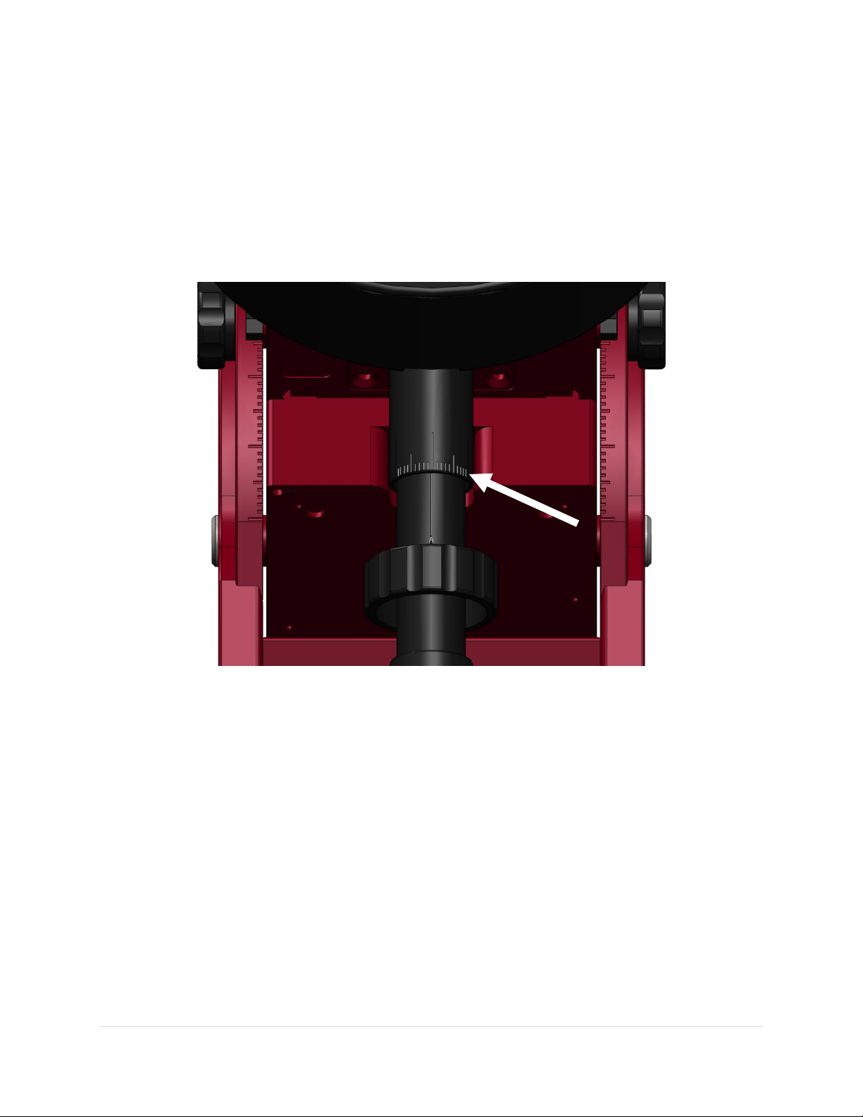
Paramount User Guide
can be used to make absolute elevation adjustments. These vertical lines are 90 degrees apart and
represent fifteen arcminute increments in elevation.
The Vernier scale also allows the mount’s elevation to be placed at a specific position and is useful for
restoring a specific elevation if the mount is used at multiple observing sites. For example, suppose your
observatory’s elevation is 39 degrees plus “an additional rotation that aligns the vertical B line with the –
4.5 tic mark on the Vernier scale”. You can subsequently use this position to precisely restore the altitude
of the polar axis each time the mount is setup.
Figure 55: The Vernier scale on the Altitude Adjuster for Paramount MX, MX+ and ME II.
Paramount MYT Altitude Scale
Figure 56 shows the location of the calibrated tic marks on the Paramount MYT. Each tic on the flat,
stationary plate represents an adjustment of approximately 2 arcminutes. Align the edge of the knob with
the tic mark when making fine adjustments.
97 | P a g e

Paramount User Guide
Model
Length
Diameter
Weight
Maximum Number
of Counterweights
47 cm (18.5 in.)
4.763 cm (1.875 in.)
6.7 kg (14.75 lb.)
Six 30 lb. or six 40
lb.
41 cm (16 in.)
3.8 cm (1.5 in.)
4 kg (9 lb.)
Six 20 lb.
33 cm (13 in.)
3.8 cm (1.5 in.)
3.2 kg (7 lb.)
Four 20 lb. or 10 lb.
Always attach the counterweight shaft is attached before operating the mount. The
weight of the counterweight shaft helps balance the unloaded right ascension axis.
Attempting to slew the mount when either axis is severely out of balance may cause
the motors to stall and the control system will emit successive beeps.
Figure 56: When making fine adjustments, align the edge of the knob with the stationary tic mark to determine relative
motion.
Counterweight Shaft
To attach the stainless steel counterweight shaft to the Paramount, insert the threaded end into the
bottom of the declination assembly (Figure 45) and rotate the shaft clockwise until it is hand tight. The
counterweight shaft changes the mount’s center of mass and may make the unit “top heavy,” so make
sure to install the secure the mount to the pier or tripod first.
98 | P a g e
Paramount User Guide
Model
Counterweight Specifications
14 kg (30 lb.), 1.875 in. bore
Technical drawing URL: http://www.bisque.com/sc/media/p/74654.aspx
In addition to the 1.875-in. diameter counterweight shaft, the Paramount ME II can also
accept the 1.5-in. diameter Paramount ME/MX counterweight shaft.
9 kg (20 lb.), 1.5 in. bore
Technical drawing URL: http://www.bisque.com/sc/media/p/70864.aspx
4.5 kg (10 lb.), 1.5 in. bore
Counterweights are extremely heavy! Please use extreme
caution so that you do not accidentally drop one and injure
yourself or others!
Counterweight Shaft Extension Bar (Optional)
The optional counterweight shaft extension bar (sold separately) screws into the end of the Paramount
standard counterweight shaft. This bar both extends the moment arm and allows up to two additional
counterweights for ultra-heavy payloads.
Counterweights
Two counterweights are included with the Paramount and can be mounted on the counterweight shaft
to balance the mount’s payload. Slide the counterweight to the approximate balance position, and then
rotate the counterweight knob until the knob is hand tight. A softer metal brass plunger on the end of
the knob holds the counterweight in place and will not score or gouge the stainless steel shaft.
The table below shows the counterweight specifications by model.
The amount of counterweight required to achieve balance depends on the total weight of the optical tube
assembly and accessories, and how the weight is distributed. Before adding any counterweights to the
counterweight shaft, first estimate how much counterweight is required, and then add this amount to the
counterweight shaft. Err on the heavy side. The counterweights should initially “outweigh” the optical
tube assembly by being too far down the shaft. This way, when fine-tuning the balance, the
counterweight shaft will tend to rotate so that the counterweights are downward, instead of your
expensive equipment.
Once sufficient counterweights are added, the right ascension axis should be very “bottom heavy.” At
this point, adding the optical tube assembly should result in a system that is somewhat close to being
balanced.
99 | P a g e

Paramount User Guide
Never position the Paramount in the above orientation, with or
without counterweights!
Figure 57 shows the Paramount in an unstable configuration that places extreme and
potentially destructive lateral force on the teeth of the right ascension worm and gear. The
counterweight shaft should always remain in the vertical position while the Paramount is
being loaded with counterweights and payload (telescope, camera, etc.).
If you must orient the mount’s payload in a severely out of balance position, for the
Paramount MX, place the Three Position Switch in the Lock position first (page 73), for the
Paramount ME II install the locking bolts and place the Two Position Switch to balance, and
for the Paramount MX+ place the Two Position Switch to balance and pull and rotate the
transport lock knob 90 degrees to a lock position.
Even when mount’s axis is locked, the excessive imbalance demonstrated above could
bend, mar or otherwise damage the shaft or bolts that lock the axis in place. Please do not
abuse your precision mount in this manner.
After the counterweights are added, firmly tighten each of the counterweight knobs to ensure they do
not slip. Also, make sure to install the counterweight safety knob on the bottom of the counterweight
shaft.
Figure 57: Please, never ever place any model Paramount mount in this orientation, not even with a single counterweight.
100 | P a g e
 Loading...