

Paramount Fitness MS-1000, MS-1050 Assembly Manual

ASSEMBLY MANUAL
OPTIONAL STATION
MS-1000/1050
ADJUSTABLE CABLE COLUMN
MS-1000 Right Side
MS-1050 Left Side
AM-MS1000.fm
Rev 04-02

SAFETY REQUIREMENTS
1. Review and understand all of the warning labels affixed to the machines and the facility
safety sign. Replace any warning l abel at the first sign of wear. Labels and the Facility Safety
Sign may be obtained from Paramount free of charge.
2. Be certain that machine operation is understood before machine is used. Refer to the
instruction label provided with the machine.
3. Keep children away from this equipment.
4. DO NOT high-pin or double-pin the weight stack. DO NOT allow the mac hin e to be used if the
top plate or weight stack is pinned i n a raised position. Use an assistant and carefully return
the machine to the proper position with the cap plate resting on the top weight. Inspect the
cable to ensure that it is seated in all of the pulleys.
5. Use ONLY Paramount weight selector pins. Other manufacturer’s pins way work free of the
weight stack causing possible injury . Be certain the pin is completely inserted prior to use.
6. Cables: Inspect the entire cable and the end fittings daily. Pay close attenti on to the area
going over the pulleys and to the end connections. When adjusting cables at the threaded
inserts make sure all connections are tight. Adjust tension on cables as needed. Replace all
cables at first signs of wear. Use only Paramount supplied replacement cables. Ensure
that the dimension from under the bol t head to t he t op surface of the sel ector b ar i s no great er
than 1-3/8 inches (see installation). Ensure that the cable tension bolt & nut are tight.
7. Adjustment Pins: check the function of select or pins on adjustable pulley housings. Make
sure that the selector pin inserts completely into each position without binding.
8. Nuts, Bolts, and Fasteners: Check tightness weekly. If any hardware has become loose,
retighten and/or use Loctite
TM
Threadlocker 242.
9. Frames and Lifting Ar ms: Inspect weekly for integrity and function. Replace any component
at first signs of wear.
10. DO NOT attempt to free any jammed assemblies by yourself as this may result in injury.
11. Instruct Users not to wear loose or dangling clothes or have headphone wires hanging when
using this equipment.
12. Recommend that users receive a medical exam before commencing an exercise program.
User should stop exercising if they feel faint or dizzy.
13. Regularly Check the function of your machine by verifying the following:
•Cables and end fittings are intact and tensioned properly.
•All adjustments are possible and carried out with ease.
•The proper selector pin is in the weight stack.
•The exercise is performed smoothly, free of noise and/or binding.
•The guide rods are properly lubricated.
14. Follow the installation guidelines provided with the products.
15. Retain these instr uctions for future reference.
If you have any questions, do not hesit ate to cont act your Paramoun t Dealer of Paramount Fi tness
Corp. at (800) 721-2121 or www.paramountfitness.com.
Refer to Maintenance Schedule label located on the machine for maintenance intervals.
2 MS Assembly Instructions PT1.fm

MAINTENANCE REQUIREMENTS
• Frames: Wipe all machines down with a damp cloth and dry completely each da y. This
includes painted and chrome parts and upholstered pads.
• Painted/chrome parts: Use Simple Green or similar cleaner for light di rt and gri me. Use TurtleWax® Polishing Compound or a good car polish to remove heavier dirt and grease as well
as for polishing. DO NOT use sol vents, l acquer thinner, acetone or finger nail polis h remover .
For scuffs and marks that are not removed by the above methods use a soft scrub cleanser.
• Upholstery: Use cloth towels and warm water daily to remove surface dirt and perspiration.
Use a lanolin based hand cleaner or Naugahyde® brand upholstery cleaner to condition and
deep clean on a weekly basis. DO NOT use Windex, Simple Green, 409, or similar products
to clean the upholstery.
• Weight stack enclosures (shrouds): Wipe down with a damp cloth as needed.
• Exercise instruction labels: Clean with soap and water as needed.
• Guide rods: Wipe all dirt and dust off the guide r ods befo re applyi ng a light applicat ion of Tri-
TM
Flow
guide rods with the rag. DO NOT use light oil base lubricants such as WD-40. Caution: Tri-
Flow
• Bronze bushings: Check monthly for signs of wear and replace as needed. Lubricate
monthly with Tri-Flow
We recommend that you purchase the Paramount Performance Kit (P/N KIT-01) to maintain your Paramount products. This will insure that the proper maintenance materials
required will be used. Please refer to the General Maintenance Manual (p/n AM-GMM)
for other important safety and maintenance information.
or other silicone spray l ubricant, spr aying the T ri-FlowTM on a rag and then wiping the
TM
will stain carpet and clothing.
TM
.
ASSEMBLY NOTES
• It is recommended that at least two (2) people be used to assemble this machine.
• Read the assembly instructions completely before beginning to assemble the
machine. This will help you to become familia r with the machine and prevent mistakes requiring unnecessary disassembly and reassembly.
• Hardware placement is indicated with a balloon. Refer to the hardware page for co rresponding size and configuration. You may have some remaining hardware as extra
pieces are alw ays included in on e of the bags.
• Install all plastic end caps on assemblies where necessary before assembling the
machine.
• Initially tighten all hardware by hand, as this will assist in the alignment of the
machine. When the framewo rk of the ma chin e is complete , tigh ten all nuts, bolts and
setscrews. Be sure all hardware is tight before using the machine.
• Bolts should point inward on the machine wherever possible, leaving the bolt heads
facing out.
• Route cables prior to installing pulley whee ls.
• Read and understand all machine warning and instruction labels before using the
machine.
3 MS Assembly Instructions PT1.fm

HARDWARE MEASUREMENT GUIDE
As shown below, Button Head, Socket Head and Hex Head screw length is measured
from the bottom of the head to the end of the screw. The length of Flat Head screws is
measured as the total overall length.
BHCS - BUTTON HEAD CAP SCREW
SHCS - SOCKET HEAD CAP SCREW
FHCS - FLAT HEAD CAP SCREW
HHCS - HEX HEAD CAP SCREW
MEASURE BOLT
FROM HERE
TOOLS REQUIRED
STEP LADDER
1
SOCKET
WRENCH
2
SOCKET
9/16”
3/4”
3
WRENCH
9/16”
3/4”
7/8”
15/16”
45
ALLEN WRENCH
5/32”
7/32”
5/16”
4 MS Assembly Instructions PT1.fm

MS-1000/1050 ASSEMBLY INSTRUCTIONS
1. Your MS-1000 (ri ght side ha ndl e ) or MS-10 50 (l e ft side handle) adjustabl e cabl e column stations require minimal assembly to comp lete. These assembly instructions
may vary slightly depending upon the method of shipment.
2. To complete the installation, you will need an available side “A” on a 4-sided modular
frame. Each station will add an additi onal 10-3/4” to the overall size of the unit (see
diagram below). The minimum ceiling height requirement is 93”.
Total weight per station with 170 lb. stack = 270 lbs. (123 kg.)
Total weight per station with 250 lb. stack = 350 lbs. (159 kg.)
MS-1000
RIGHT SIDE HANDLE
MS-1050
LEFT SIDE HANDLE
5 MS-1000 PT1.fm

PLACEMENT OF OPTIONAL STAT IONS
Optional stat ions are d esigned to fi t a parti cular side of your MS M odular Frame. Use the
diagram below to determine the correct side of the modular frame that the optional stations should be attached. Note that the optional stations are referred to as either Side
“A” or Side “B” Stations.
MS-4000
Optional Stations = 4
- (2) Side “A” St a tio ns .
- (2) Side “B” Stations.
MS-5000
Optional Stations = 3
- (1) Side “A” Station.
- (2) Side “B” Stations.
MS-6000
Optional Stations = 2
- (2) Side “B” Stations.
MS-8000
Optional Stations = 6
- (2) Side “A” Stations.
- (4) Side “B” Stations.
A
A
A
B
B
B
B
B
B
A
B
B
B
A
B
MS-12000
Optional Stations = 8
- (2) Side “A” Stations.
- (6) Side “B” Stations.
A
IMPORTANT!
IF YOU DID NOT ORDER AN OPTIONAL SIDE “A” STATION FOR ANY OF THE
ABOVE CONFIGURATIONS, A HALF-BLANK STATION (MS-0005) MUST BE
INSTALLED IN PLACE OF EACH SIDE “A” STATION.
B
B
B
B
A
B
6 MS-1000 PT1.fm
B
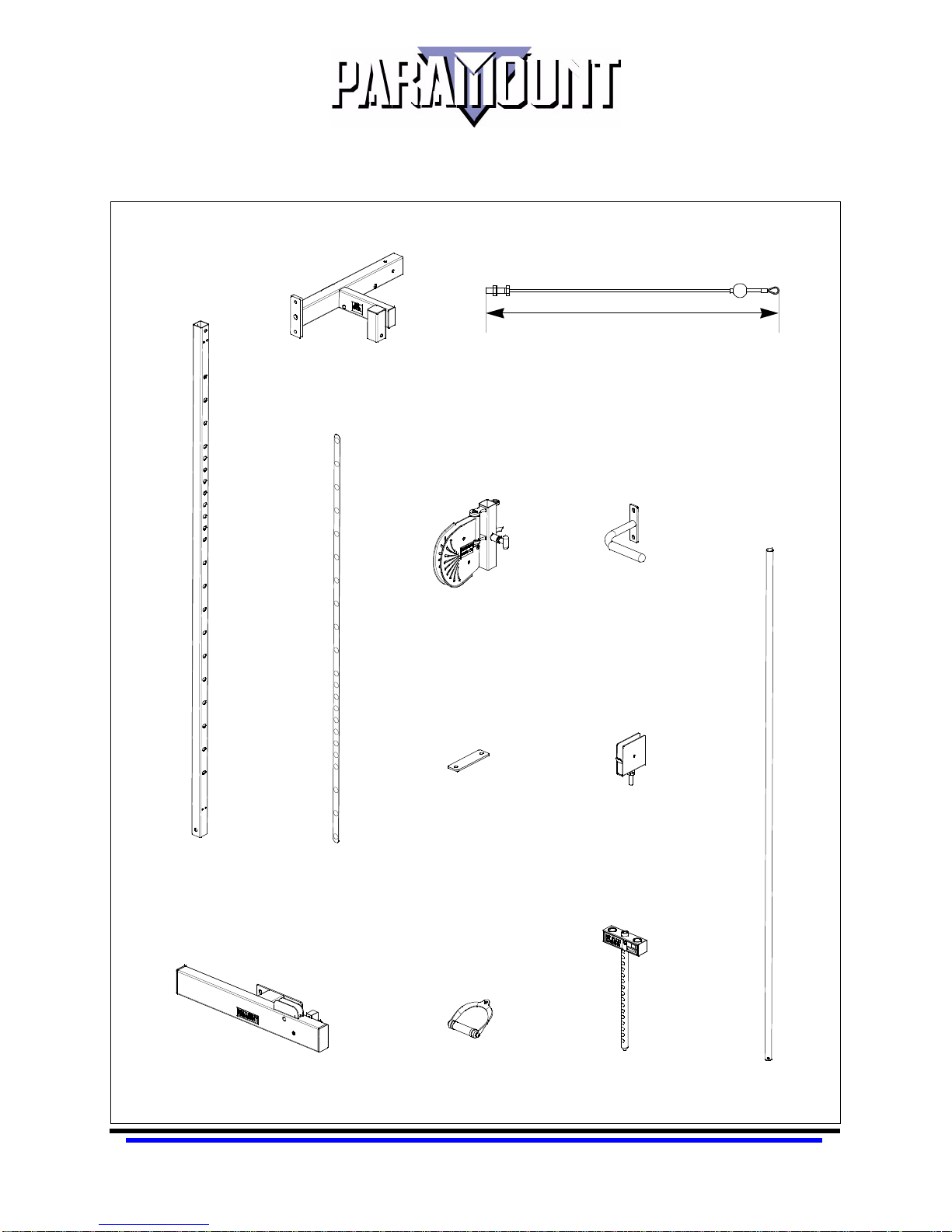
MS-1000 COMPONENTS
RIGHT SIDE
(see following page for left side)
Note: Depending upon the method of shipment, some
of the items that appear may already be assembled
to your machine.
MS1002000X
TOP PULLEY
HOUSING (RIGHT)
MS1002035X
ADJUSTABLE PULLEY
(RIGHT)
351-1/2 in. (893 cm)
MS1002090
CABLE
MS1002050X
HANDLE
MS1002061
ADJUSTMENT
COLUMN
MS1002010X
BOTTOM PULLEY
HOUSING (RIGHT)
B5000
ADJUSTMENT
LABEL
MS8002002
BEAM CONNECTOR
B1100
HANDLE
7 MS-1000 PT1.fm
MS1002020X
CAP PLATE PULLEY
9099780X
SELECTOR BAR
MS8002009X
GUIDE ROD (2)
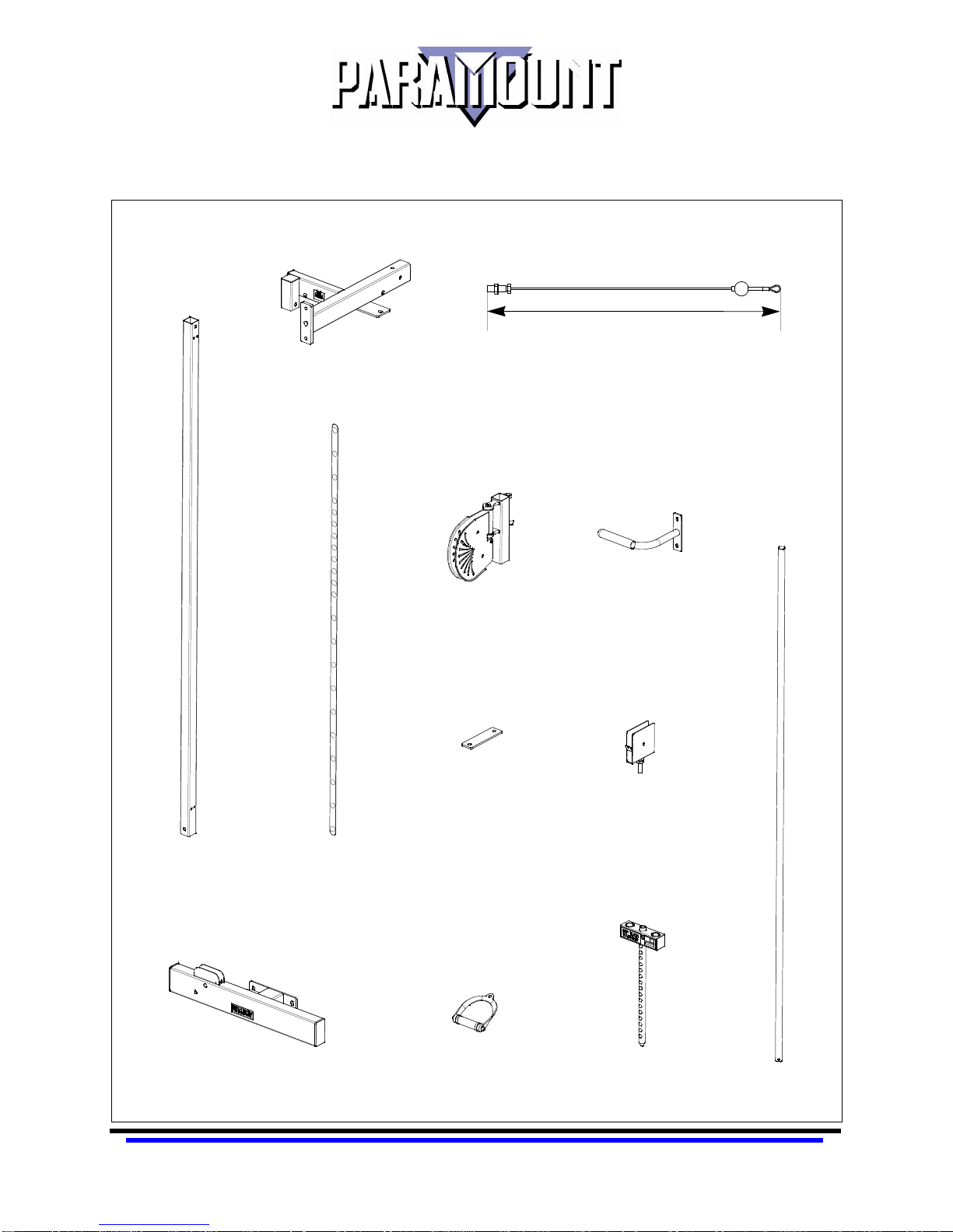
MS-1050 COMPONENTS
LEFT SIDE
(see previous page for right side)
Note: Depending upon the method of shipment, some
of the items that appear may already be assembled
to your machine.
MS1002005X
TOP PULLEY
HOUSING (LEFT)
MS1002030X
ADJUSTABLE PULLEY
(LEFT)
351-1/2 in. (893 cm)
MS1002090
CABLE
MS1002050X
HANDLE
MS1002061
ADJUSTMENT
COLUMN
MS1002015X
BOTTOM PULLEY
HOUSING (LEFT)
B5000
ADJUSTMENT
LABEL
MS8002002
BEAM CONNECTOR
B1100
HANDLE
8 MS-1000 PT1.fm
MS1002020X
CAP PLATE PULLEY
9099780X
SELECTOR BAR
MS8002009X
GUIDE ROD (2)
 Loading...