

Paramont PAR 4MP User Manual

Paramont Cameras
User Manual: PAR 4MP Series

Notes on Safety
This product is intended to be supplied by a Listed Power Unit, marked with 'Limited
Power Source', 'LPS' on unit, output rated minimum 12V/2 A or POE 48V/
350mA(depending on models), no more than 2000m altitude of operation and Tma=60
Deg.C.
As for the modes with PoE function, the function of the ITE being investigated to IEC
60950-1 standard is considered not likely to require connection to an Ethernet network
with outside plant routing, including campus environment and the ITE is to be
connected only to PoE networks without routing to the outside plant.
Risk of explosion if battery is replaced by an incorrect type. Dispose of used batteries
according to the instructions.
Do not attempt to disassemble the camera; in order to prevent electric shock, do not
remove screws or covers.
There are no user-serviceable parts inside. Please contact the nearest service center as
soon as possible if there is any failure.
Avoid from incorrect operation, shock vibration, heavy pressing which can cause
damage to product.
Do not use corrosive detergent to clean main body of the camera. If necessary, please
use soft dry cloth to wipe dirt; for hard contamination, use neutral detergent. Any
cleanser for high grade furniture is applicable.
Avoid aiming the camera directly towards extremely bright objects, such as, sun, as this
may damage the image sensor.
Please follow the instructions to install the camera. Do not reverse the camera, or the
reversing image will be received.
Do not operate it in case temperature, humidity and power supply are beyond the limited
stipulations.
Keep away from heat sources such as radiators, heat registers, stove, etc.
Do not expose the product to the direct airflow from an air conditioner.
This manual is for using and managing the product. We may reserve the rights of
amending the typographical errors, inconsistencies with the latest version, software
upgrades and product improvements, interpretation and modification. These changes
will be published in the latest version without special notification.
All pictures, charts, images in this manual are only for description and explanation of
our products. The ownerships of trademarks, logos and other intellectual properties
related to Microsoft, Apple and Google belong to the above-mentioned companies.
This manual is suitable for IR water-proof network cameras.

Table of Contents
1 Introduction ................................................................................................................... 1
2 IE Remote Access ........................................................................................................... 2
2.1 LAN ................................................................................................................................................ 2
2.1.1 Access through IP-Tool .................................................................................................. 2
2.1.2 Directly Access through IE ............................................................................................. 3
2.2 WAN ............................................................................................................................................... 5
3 Live View ........................................................................................................................ 8
4 Network Camera Configuration ................................................................................. 11
4.1 System Configuration.................................................................................................................... 11
4.1.1 Basic Information ......................................................................................................... 11
4.1.2 Date and Time .............................................................................................................. 11
4.1.3 Local Config ................................................................................................................. 12
4.1.4 Storage.......................................................................................................................... 12
4.2 Image Configuration ..................................................................................................................... 14
4.2.1 Display Configuration .................................................................................................. 15
4.2.2 Video / Audio Configuration ........................................................................................ 17
4.2.3 OSD Configuration ....................................................................................................... 18
4.2.4 Video Mask .................................................................................................................. 18
4.2.5 ROI Configuration ........................................................................................................ 19
4.2.6 Lens Control ................................................................................................................. 20
4.3 PTZ Configuration ........................................................................................................................ 21
4.4 Alarm Configuration ..................................................................................................................... 21
4.4.1 Motion Detection .......................................................................................................... 21
4.4.2 Other Alarms ................................................................................................................ 23
4.4.3 Alarm In ....................................................................................................................... 24
4.4.4 Alarm Out ..................................................................................................................... 25
4.4.5 Alarm Server ................................................................................................................ 26
4.5 Event Configuration ...................................................................................................................... 26
4.5.1 Object Removal ............................................................................................................ 27
4.5.2 Exception ...................................................................................................................... 29
4.5.3 Line Crossing ............................................................................................................... 30
4.5.4 Intrusion ....................................................................................................................... 33
4.5.5 Crowd Density Detection.............................................................................................. 35
4.5.6 People Intrusion ............................................................................................................ 37
4.5.7 People Counting ........................................................................................................... 38
4.6 Network Configuration ................................................................................................................. 41
4.6.1 TCP/IP .......................................................................................................................... 41
4.6.2 Port ............................................................................................................................... 42
4.6.3 Server Configuration .................................................................................................... 43
4.6.4 DDNS ........................................................................................................................... 43

Network Camera User Manual
4.6.5 SNMP ........................................................................................................................... 44
4.6.6 802.1x ........................................................................................................................... 45
4.6.7 RTSP ............................................................................................................................ 46
4.6.8 UPNP ........................................................................................................................... 47
4.6.9 Email ............................................................................................................................ 48
4.6.10 FTP ............................................................................................................................... 49
4.6.11 QoS............................................................................................................................... 50
4.7 Security Configuration .................................................................................................................. 50
4.7.1 User Configuration ....................................................................................................... 50
4.7.2 Online User .................................................................................................................. 51
4.7.3 Block and Allow Lists .................................................................................................. 52
4.8 Maintenance Configuration ........................................................................................................... 52
4.8.1 Backup and Restore ................................ ................................................................ ...... 52
4.8.2 Reboot .......................................................................................................................... 53
4.8.3 Upgrade ........................................................................................................................ 53
4.8.4 Operation Log ............................................................................................................... 54
5 Search ........................................................................................................................... 55
5.1 Photo Search ................................................................................................................................ . 55
5.2 Video Search ................................................................................................................................. 56
5.2.1 Local Video Search ....................................................................................................... 56
5.2.2 SD Card Video Search .................................................................................................. 57
Appendix ................................................................................................................................ 59
Appendix 1 Q & A ................................................................................................................. 59
Appendix 2 Installation of Water-proof Rubber Plug ....................................................... 60
Appendix 3 Specifications .................................................................................................... 61
1
Network Camera User Manual
1 Introduction
This IP-CAMERA (short for IP-CAM) is designed for high performance CCTV solutions. It
adopts state of the art video processing chips. It utilizes most advanced technologies, such as
video encoding and decoding technology, complies with the TCP/IP protocol, SoC, etc to
ensure this system more stable and reliable.
This product is widely used in banks, telecommunication systems, electricity power
departments, law systems, factories, storehouses, uptowns, etc. In addition, it is also an ideal
choice for surveillance sites with middle or high risks.
Main Features
ICR auto switch, true day/night
3D DNR, true WDR
ROI coding
Support BLC, Defog, Anti-flicker
Support smart phone, iPad, remote monitoring
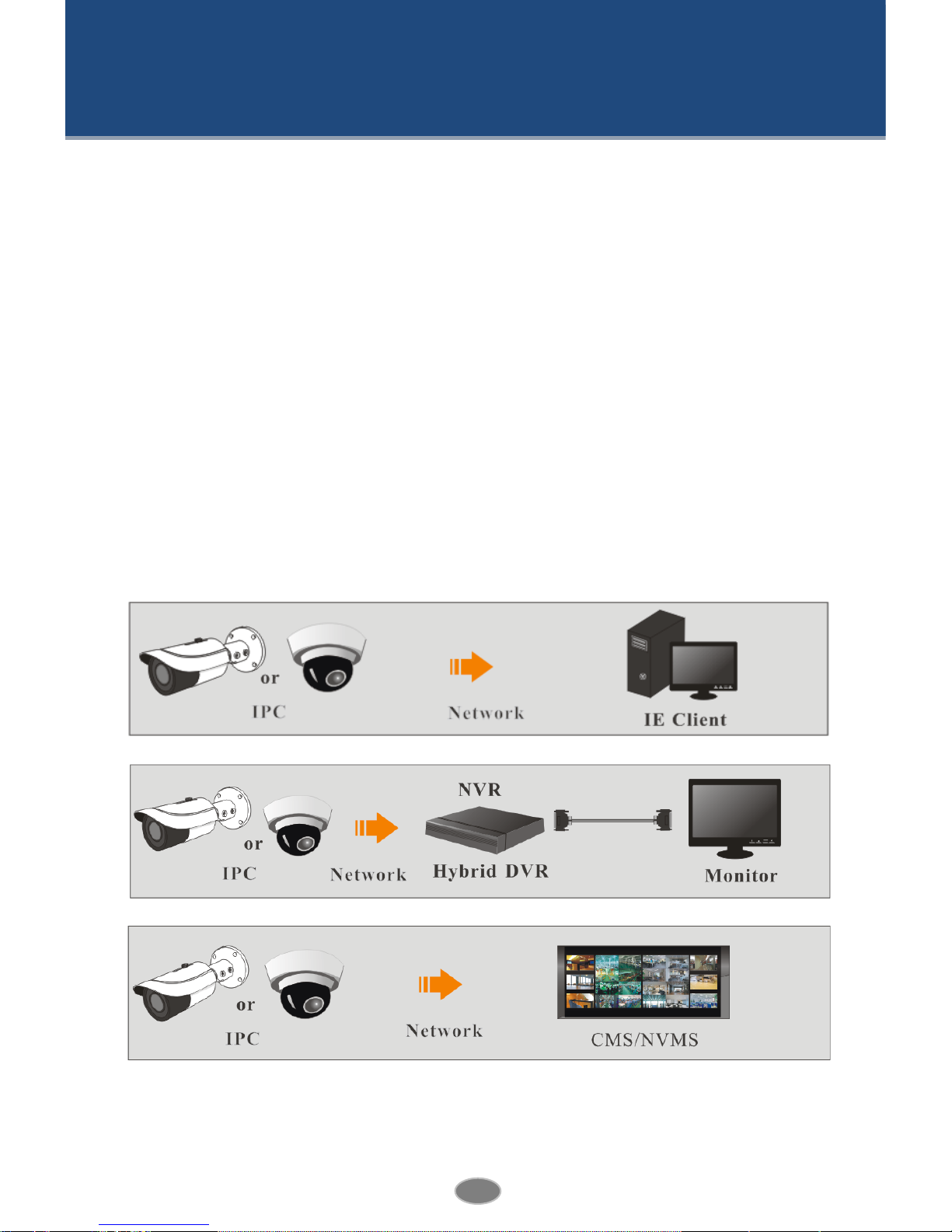
Surveillance Application
2
Network Camera User Manual
2 IE Remote Access
You may connect IP-Cam via LAN or WAN. Here only take IE browser (6.0) for example.
The details are as follows:
2.1 LAN
In LAN, there are two ways to access IP-Cam: 1. access through IP-Tool; 2. directly access
through IE browser.
2.1.1 Access through IP-Tool
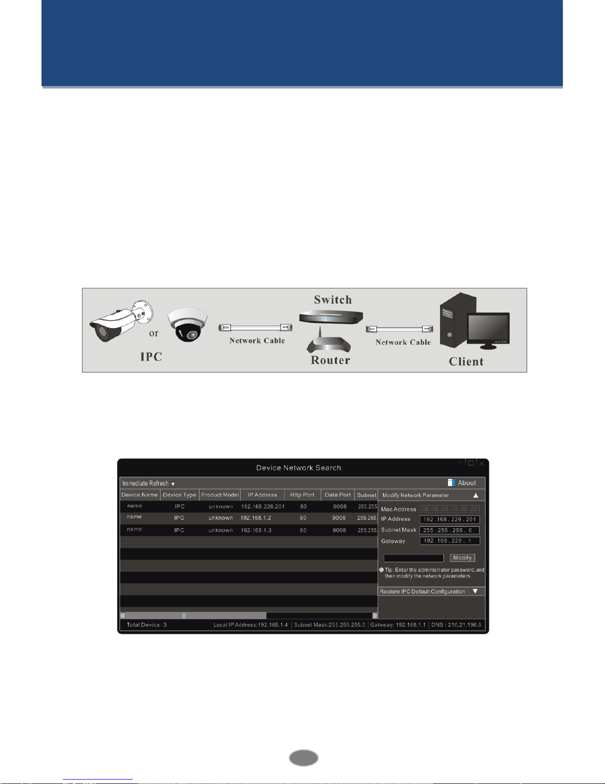
Network connection:
① Make sure the PC and IP-Cam are connected to the LAN and the IP-Tool is installed in the
PC from the CD.
② Double click the IP-Tool icon on the desktop to run this software as shown below:
③ Modify the IP address. The default IP address of this camera is 192.168.226.201. Click the
information of the camera listed in the above table to show the network information on the
right hand. Modify the IP address and gateway of the camera and make sure its network
address is in the same local network segment as that of the computer. Please modify the IP
address of your device according to the practical situation.
3
Network Camera User Manual
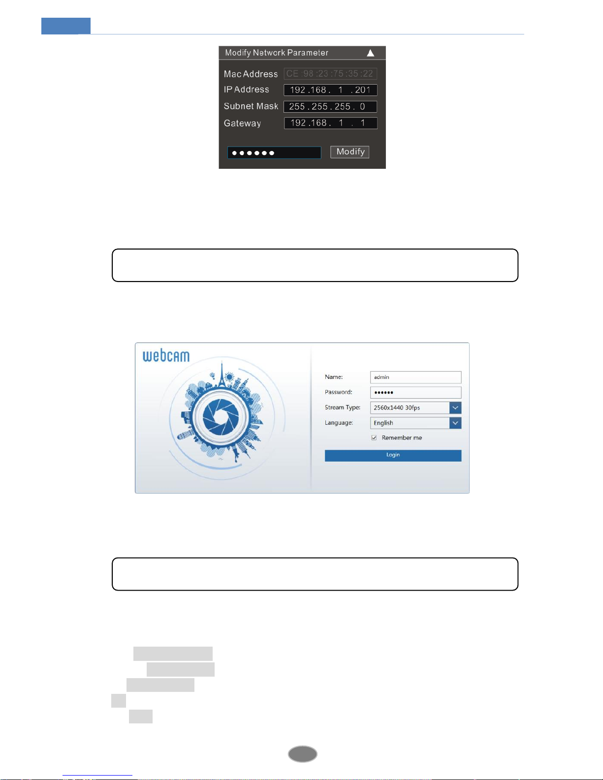
For example, the IP address of your computer is 192.168.1.4. So the IP address of the camera
shall be changed to 192.168.1.X. After modification, please input the password of the
administrator and click “Modify” button to modify the setting.
④ Double click the IP address and then the system will pop up the IE browser to connect
IP-CAM. Download, install and run the Active X control.
Input the username and password in the login window to log in. (You can modify the default
username and password for your first login for some versions)
2.1.2 Directly Access through IE
The default network settings are as shown below:
IP address: 192.168.226.201
Subnet Mask: 255.255.255.0
Gateway: 192.168.226.1
HTTP: 80
Data port: 9008
The default password of the administrator is “123456”.
The default username is “admin”; the default password is “123456”.
4
Network Camera User Manual
You may use the above default settings when you log in the camera for the first time. You may
directly connect the camera to the computer through network cable.
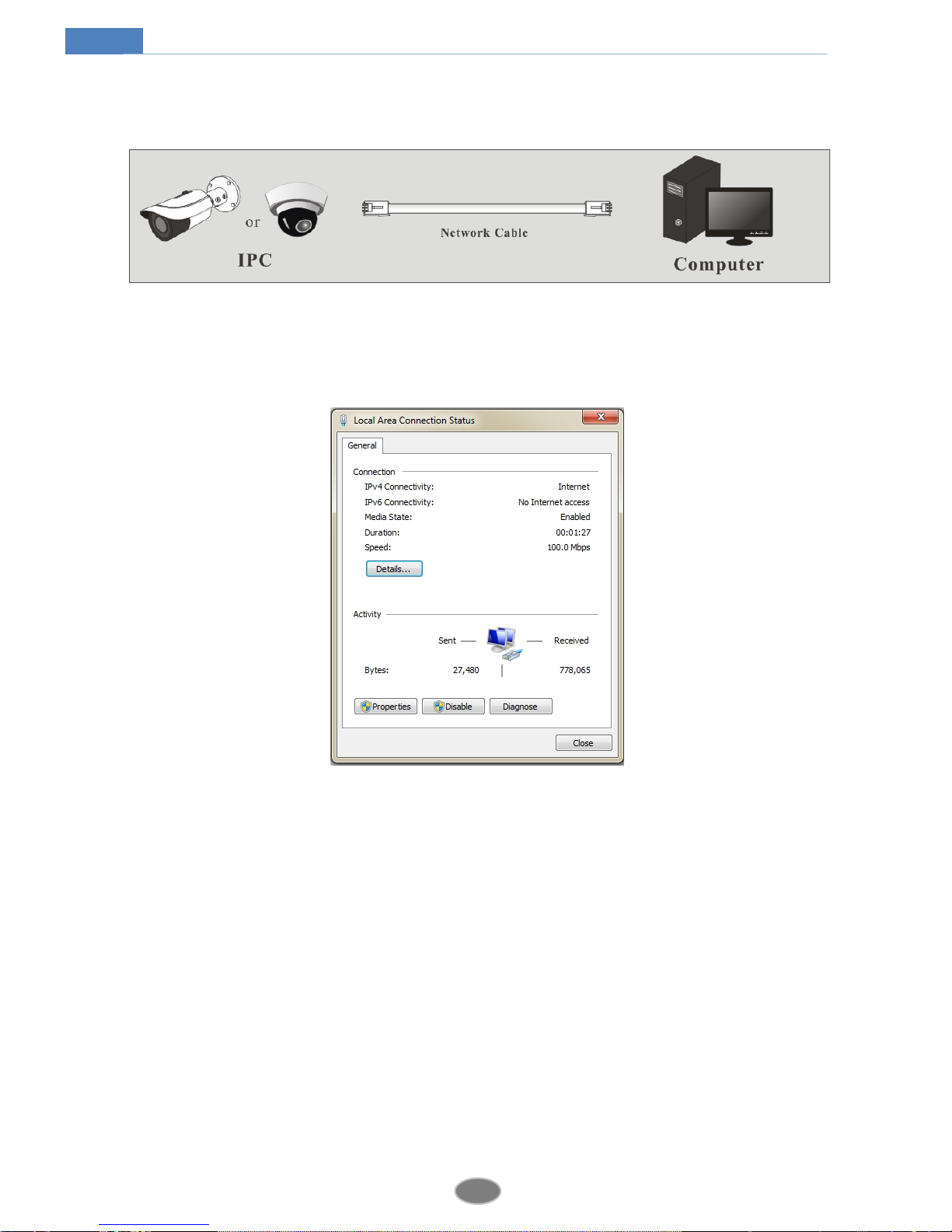
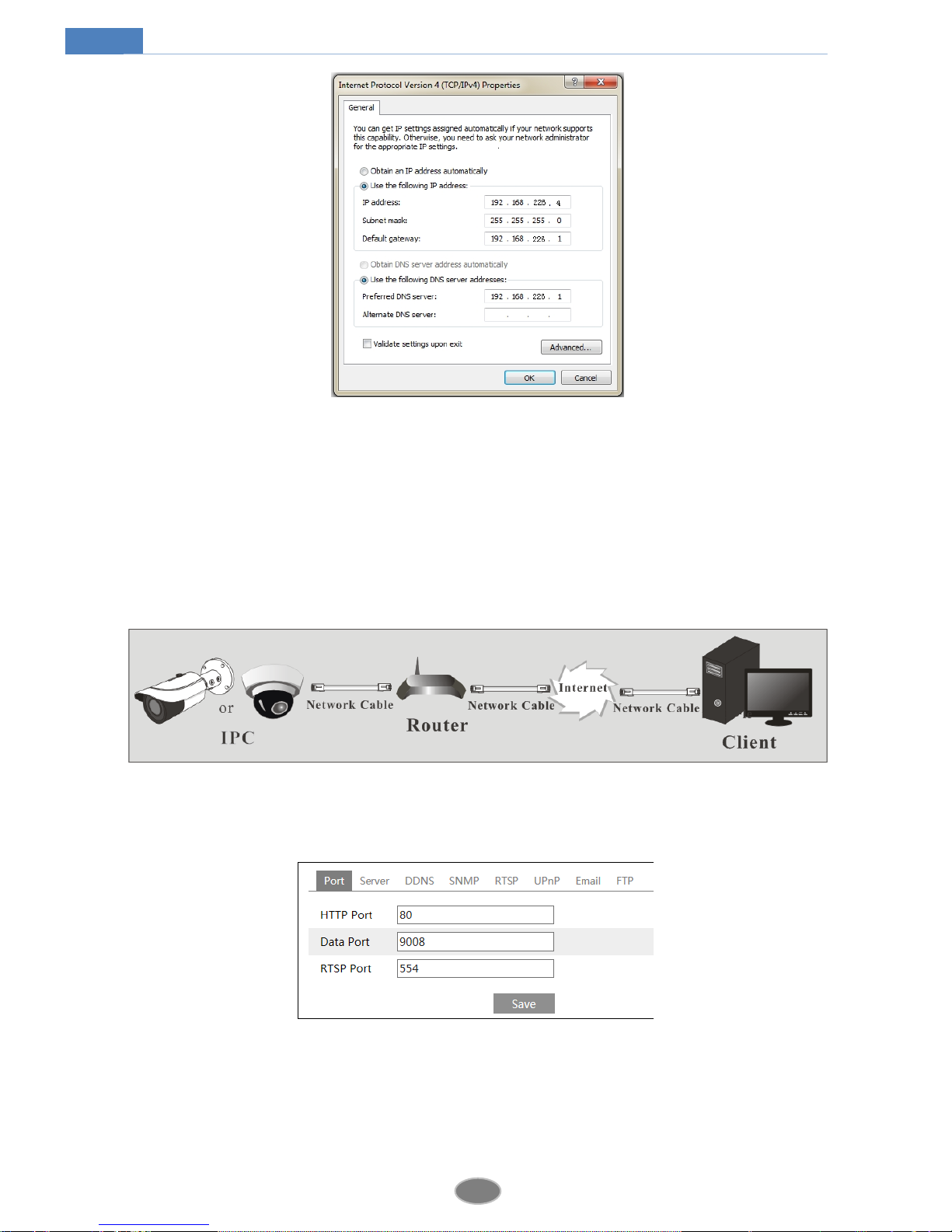
① Manually set the IP address of the PC and the network segment should be as the same as
the default settings of the IP camera. Open the network and share center. Click “Local Area
Connection” to pop up the following window.
Select “Properties” and then select internet protocol according to the actual situation (for
example: IPv4). Next, click “Properties” button to set the network of the PC.
5
Network Camera User Manual
② Open the IE browser and input the default address of IP-CAM and confirm.
③ Download, install and run the Active X control.
④ Input the default username and password in the login window and then enter to view.
2.2 WAN
Access through the router or virtual server
① Make sure the camera is well connected via LAN and then log in the camera via LAN and
go to ConfigNetworkPort menu to set the port number.
Port Setup
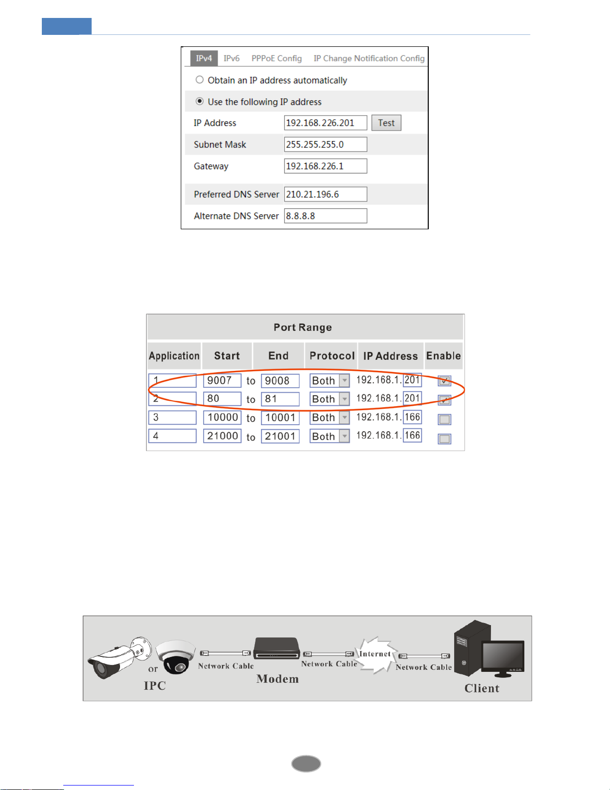
② Go to Config NetworkTCP/IP menu to modify the IP address.
6
Network Camera User Manual
IP Setup
③ Go to the router’s management interface through IE browser to forward the IP address and
port of the camera in the “Virtual Server”.
Router Setup
④ Open the IE browser and input its WAN IP and http port to access. (for example, if you
change your http port as 81, you may input “192.198.1.201:81” in the address bar of web
browser to access).
Access through PPPoE dial-up
Network connection
You may access the camera through PPPoE auto dial-up. The setting steps are as follow:

7
Network Camera User Manual
① Go to ConfigNetworkPort menu to set the port number.
② Go to Config NetworkTCP/IPPPPoE Config menu. Enable PPPoE and then input
the user name and password which you can get from your internet service provider.
③ Go to Config NetworkDDNS menu. Before you configure the DDNS, please apply
for a domain name first. Please refer to DDNS configuration for detail information.
④ Open the IE browser and input the domain name and http port to access.
Access through static IP
Network connection
The setting steps are as follow:
① Go to ConfigNetworkPort menu to set the port number.
② Go to Config NetworkTCP/IP menu to set the IP address. Check “Use the following
IP address” and then input the static IP address and other parameters.
③ Open the IE browser and input its WAN IP and http port to access.

8
Network Camera User Manual
3 Live View
After you log in, you will see the following window.
The following table is the instructions of the icons on the live view interface.
Icon
Description
Icon
Description
Original size
SD card recording indicator icon
Appropriate size
Color abnormal indicator icon
Auto
Abnormal clarity indicator icon
Full screen
Scene change indicator icon
Start/stop live view
Line crossing indicator icon
Start/stop two-way audio
Crowd density indicator icon
Enable/disable audio
People counting indicator icon
Snap
Object removal indicator icon
Start/stop recording
Intrusion indicator icon
9
Network Camera User Manual
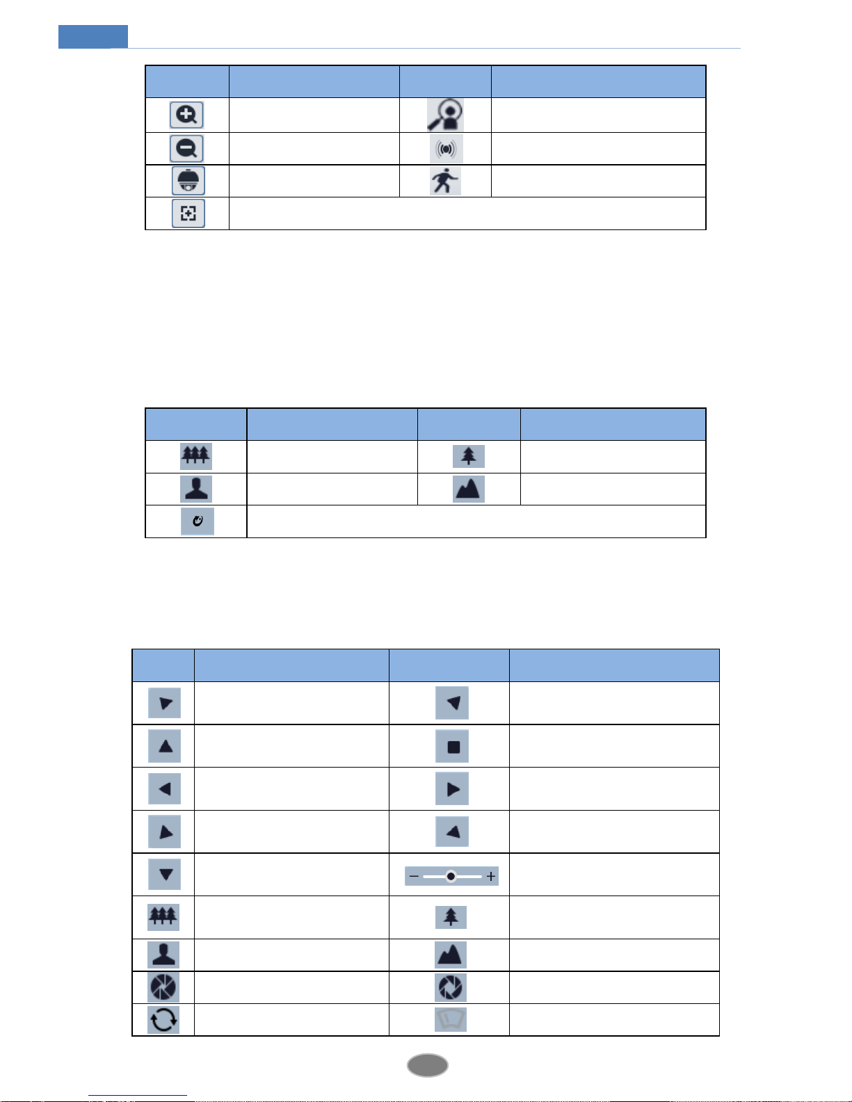
Icon
Description
Icon
Description
Zoom in
People intrusion indicator icon
Zoom out
Sensor alarm indicator icon
PTZ control
Motion alarm indicator icon
AZ control (only available for the model with motorized zoom lens )
All above-mentioned indicator icons can be displayed in live view interface only when the
corresponding event detections are enabled.
In full screen mode, double click to exit.
Click AZ control button to unfold AZ control panel. The descriptions of the control panel are
as follows:
Icon
Description
Icon
Description
Zoom -
Zoom +
Focus -
Focus +
One key focus
Click PTZ extended button to unfold PTZ control panel. In remote preview interface, you can
view the image from every direction by controlling PTZ panel.
The descriptions of the control panel are as follows:
Icon
Description
Icon
Description
Click it to rotate the dome
diagonally up-left
Click it to rotate the dome
diagonally up-right.
Click it to rotate the dome
upwards.
Click it to stop rotating the dome.
Click it to rotate the dome
towards left
Click it to rotate the dome
towards right.
Click it to rotate the dome
diagonally down-left
Click it to rotate the dome
diagonally down-right.
Click it to rotate the dome
downwards.
Drag the scroll bar to adjust
rotating speed of the dome.
Click it to zoom out the live
image.
Click it to zoom in the live image.
Focus -
Focus +
Iris -
Iris +
Auto scan
Wiper

10
Network Camera User Manual
Select preset and click to call the preset. Select and set the preset and then click to
save the position of the preset. Select the set preset and click to delete it.
Light
Radom scan
Group scan
Preset
11
Network Camera User Manual
4 Network Camera Configuration
In the Webcam client, choose “Config” to go to the configuration interface.
4.1 System Configuration
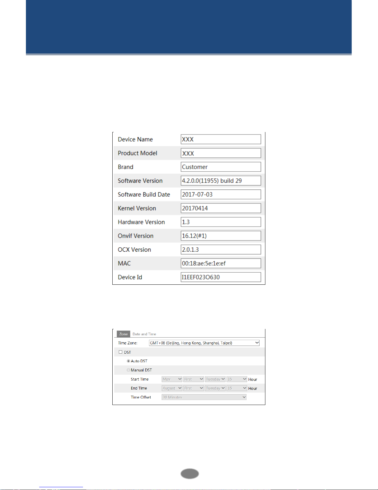
4.1.1 Basic Information
In the “Basic Information” interface, you can check the relevant information of the device.
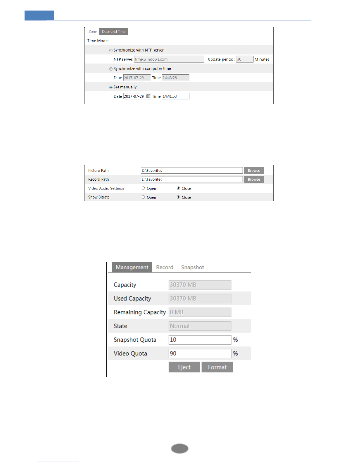
4.1.2 Date and Time
Go to ConfigSystemDate and Time. Please refer to the following interface.
You can select the time zone and DST as required.
Click “Date and Time” tab to set the time mode.
12
Network Camera User Manual
4.1.3 Local Config
Go to ConfigSystemLocal Config. You can set the storage path of the captured pictures
and video records. You can also enable or disable the bitrate display in the live view interface
and the audio of record files.
4.1.4 Storage
This function is only available for the model with SD card.
Go to ConfigSystemStorage to go to the interface as shown below.
SD Card Management
The first time you use the SD card, you should click “Format” button to format the SD card.
All data will be cleared by clicking this button.
Click “Eject” button to stop writing data to SD card. Then the SD card can be ejected safely.
Snapshot Quota: Set the capacity proportion of captured pictures in the SD card.
13
Network Camera User Manual
Video Quota: Set the capacity proportion of record files in the SD card.
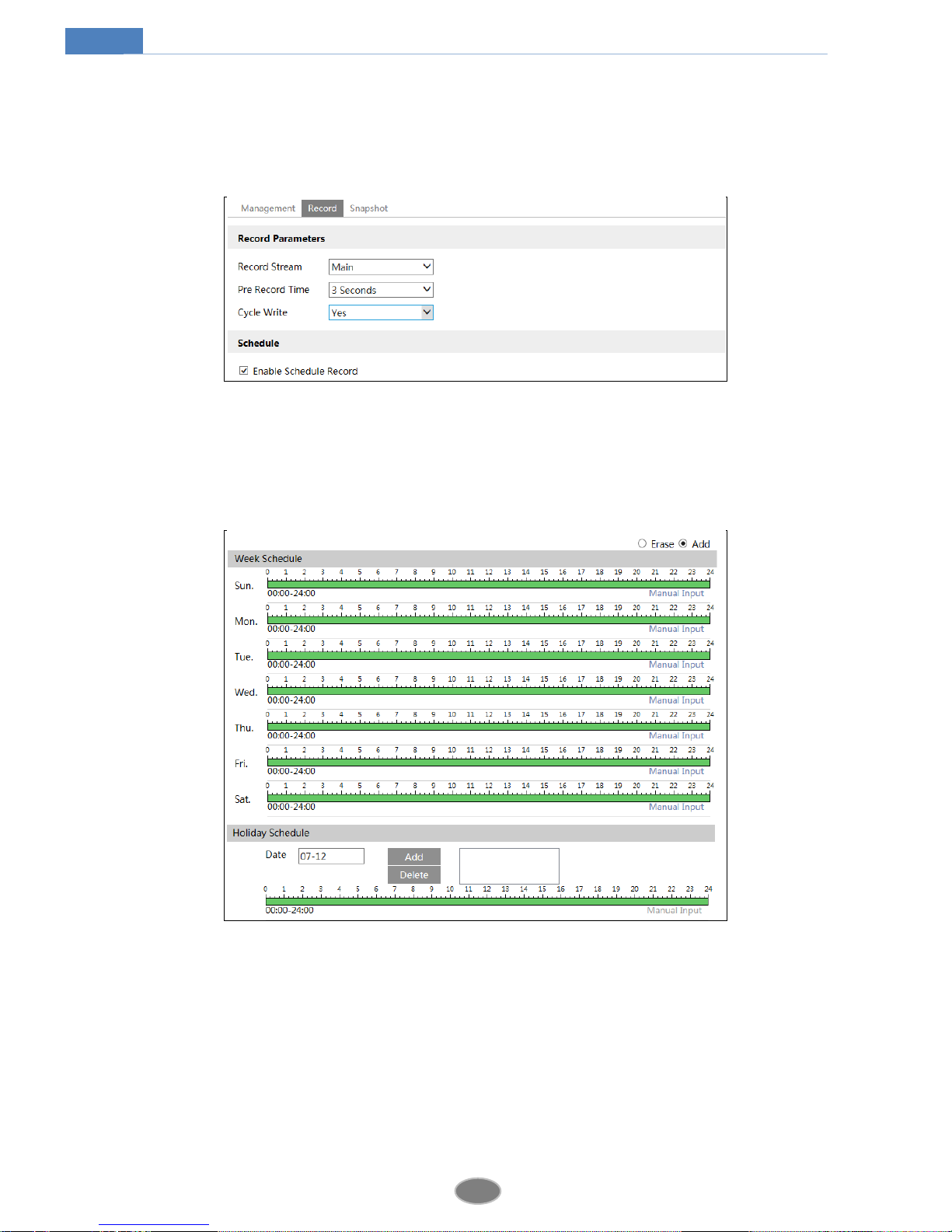
Schedule Recording Settings
1. Go to ConfigSystemStorageRecord to go to the interface as shown below.
2. Set record stream, pre-record time, cycle writing.
Pre Record Time: Set the time to record before the actual recording begins.
3. Set schedule recording. Check “Enable Schedule Record” and set the schedule.
Week schedule
Set the alarm time from Monday to Sunday for alarm everyday in one week. The lengthwise
means one day of a week; the rank means 24 hours of a day. Green means selected area.
Blank means unselected area.
“Add”: Add the schedule for a special day. Drag the mouse to set the time on the timeline.
“Erase”: Delete holiday schedule. Drag the mouse to erase the time on the timeline.
Manual Input: Click it to input the specified start and end time to add or erase the time.
Day schedule
14
Network Camera User Manual
Set alarm time for alarm in some time of a special day, such as holiday.
Set a date at the “Date” box, click “Add” button to add that date to the list box on the right
side and then drag the cursor to set the schedule of that day.
Select a date in the list box on the right side, and click “Delete” to remove the schedule on
that day.
Click “Save” button to save the settings.
Note: Holiday schedule is prior to Week schedule.
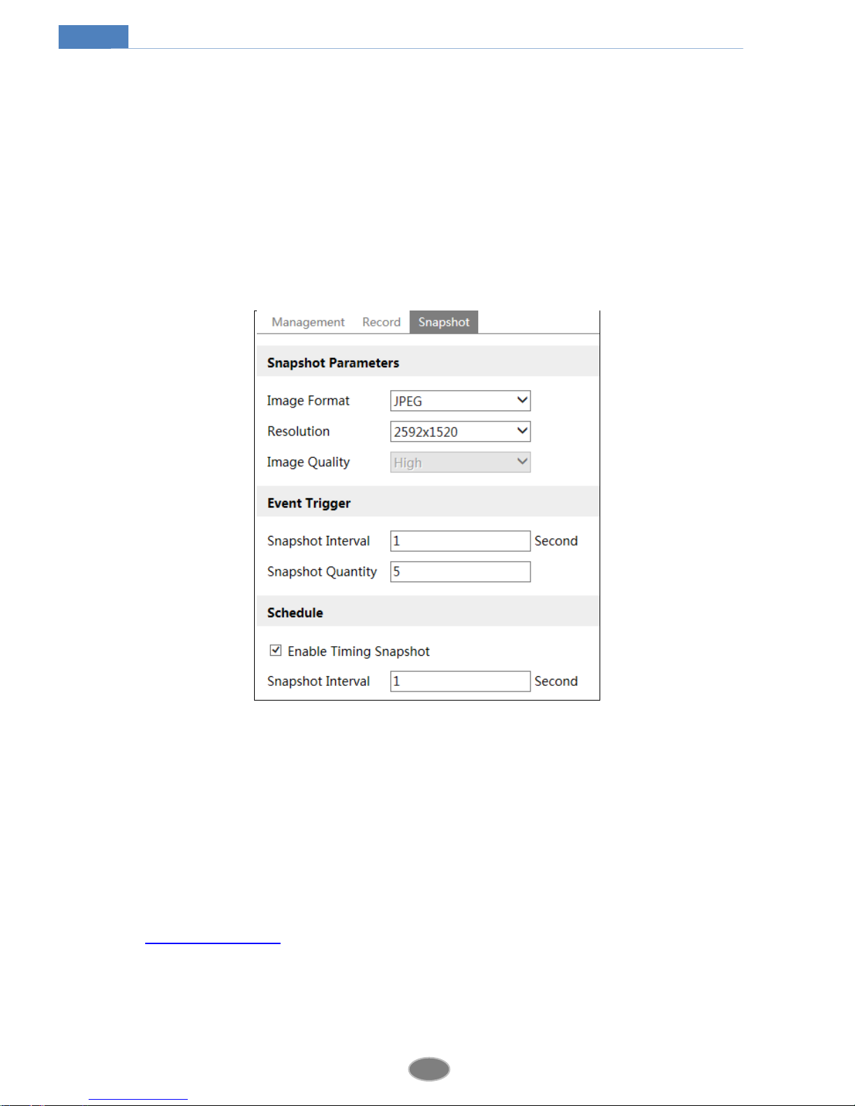
Snapshot Settings
Go to ConfigSystemStorageSnapshot to go to the interface as shown below.
Here you may set the format, resolution and quality of the image saved in the SD card and the
snapshot interval and quantity. Additionally, you can also set the timing snapshot.
Snapshot Quantity: The number you set here is the maximum quantity of snapshots. The
actual quantity of snapshots may be less than this number. Supposing the occurrence time of
an alarm event is less than the time of capturing pictures, the actual quantity of snapshots is
less than the set quantity of snapshots.
Timing Snapshot: You shall enable timing snapshot first and then set the snapshot interval
and schedule. The setting steps of schedule are the same with that of the schedule recording
(See Schedule Recording).
4.2 Image Configuration
Image Configuration includes Display, Video/Audio, OSD, Video Mask and ROI Config.
15
Network Camera User Manual
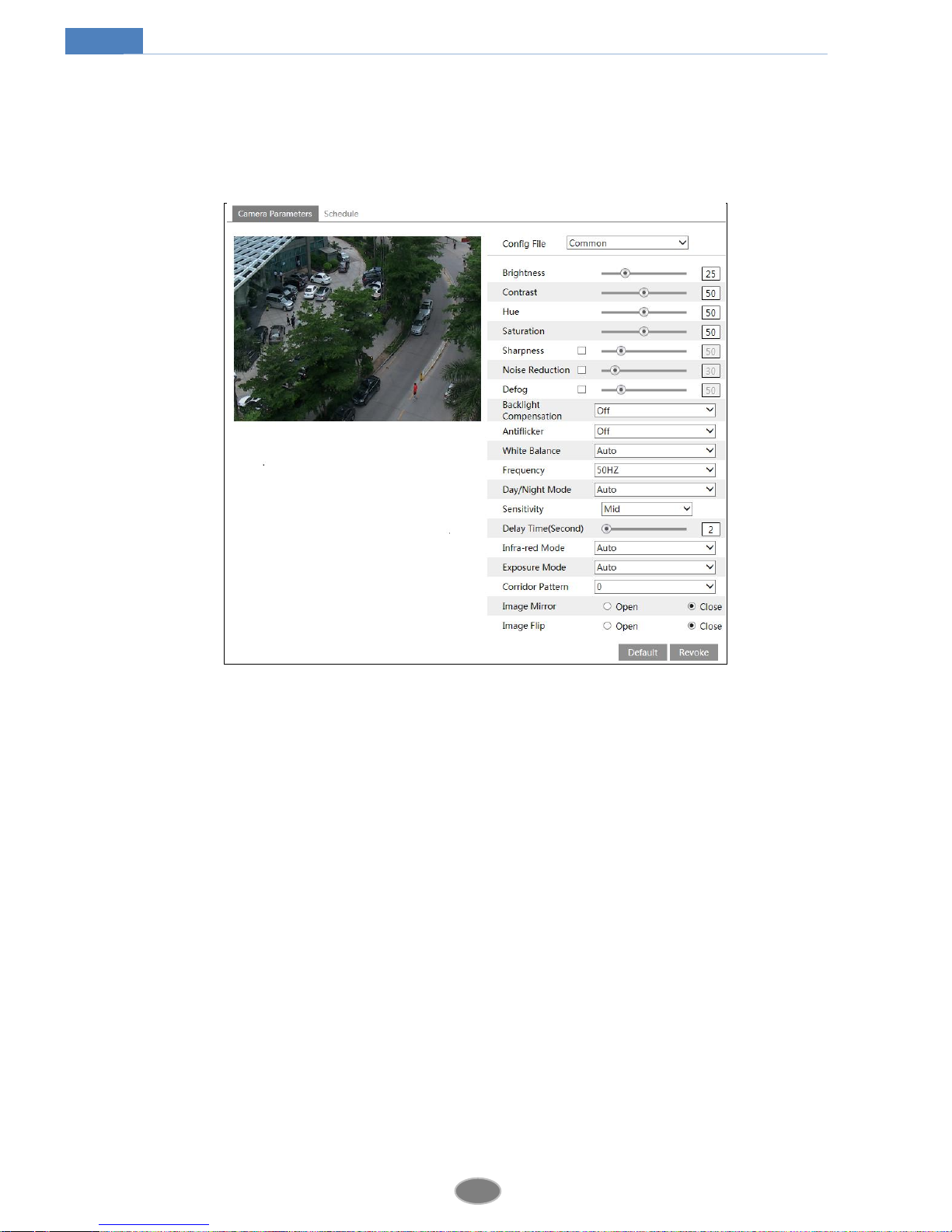
4.2.1 Display Configuration
Go to ImageDisplay interface as shown below. You can set and adjust the picture’s
brightness, contrast, hue and saturation and so on for common, day and night mode separately.
Then you can quickly see the image effect by switching the configuration file.
Brightness: Set the brightness level of the camera’s image.
Contrast: Set the color difference between the brightest and darkest parts.
Hue: Set the total color degree of the image.
Saturation: Set the degree of color purity. The purer the color is, the brighter the image is.
Sharpness: Set the resolution level of the image plane and the sharpness level of the image
edge.
Noise Reduction: Decrease the noise and make the image more thorough. Increasing the
value will make the noise reduction effect better but it will reduce the image resolution.
Defog: Activating this function and setting an appropriate value as required in foggy, dusty,
smoggy or rainy environment helps you to get clear images.
Backlight Compensation:
Off: close the backlight compensation function. It is the default mode.
WDR
As to the WDR scene, WDR will help the camera provide clear images when there are
both very bright and very dark areas simultaneously in the field of the view by lowering the
brightness of the highlight area and increasing the brightness of the lowlight area. High,
middle and low can be selected.
There will be some record lost in a few seconds during mode changing from non-WDR to
WDR mode.
16
Network Camera User Manual
HLC: lower the brightness of the whole image by suppressing the brightness of the
image’s highlight area and reducing the size of the halo area.
BLC: if enabled, the auto exposure will activate according to the scene so that the object
of the image in the darkest area will be seen clearly.
HFR: If this function is enabled, the system will restart and then the maximum value of the
frame rate of the main stream can be set to 60 fps. (Some models may not support this
function).
Antiflicker:
Off: Close the anti-flicker function.
50Hz: Make sure the horizontal stripes will not appear in the image while the device
is adjusting the exposure automatically according to the brightness of the scene.
60Hz: Make sure the horizontal stripes will not appear in the image while the device
is adjusting the exposure automatically according to the brightness of the scene.
White Balance: Adjust the color temperature according to the environment automatically.
Frequency: 50Hz and 60Hz can be optional.
Day/night Mode: Please choose the mode as needed.
Sensitivity: High, middle and low can be selected.
Infrared Mode: You may choose “ON”, “OFF” and “Auto” as required. (Some models may
not support the infrared mode).
Exposure Mode: You may choose “Auto” or “Manual” as required.
Corridor Pattern: You can change the direction of the video image by using this function. 0,
90, 180 and 270 are available. The default value is 0. The video resolution should be 1080P or
under 1080P if you use this function.
Image Mirror: Reverse the current video image right and left.
Image Flip: Turn the current video image upside down.
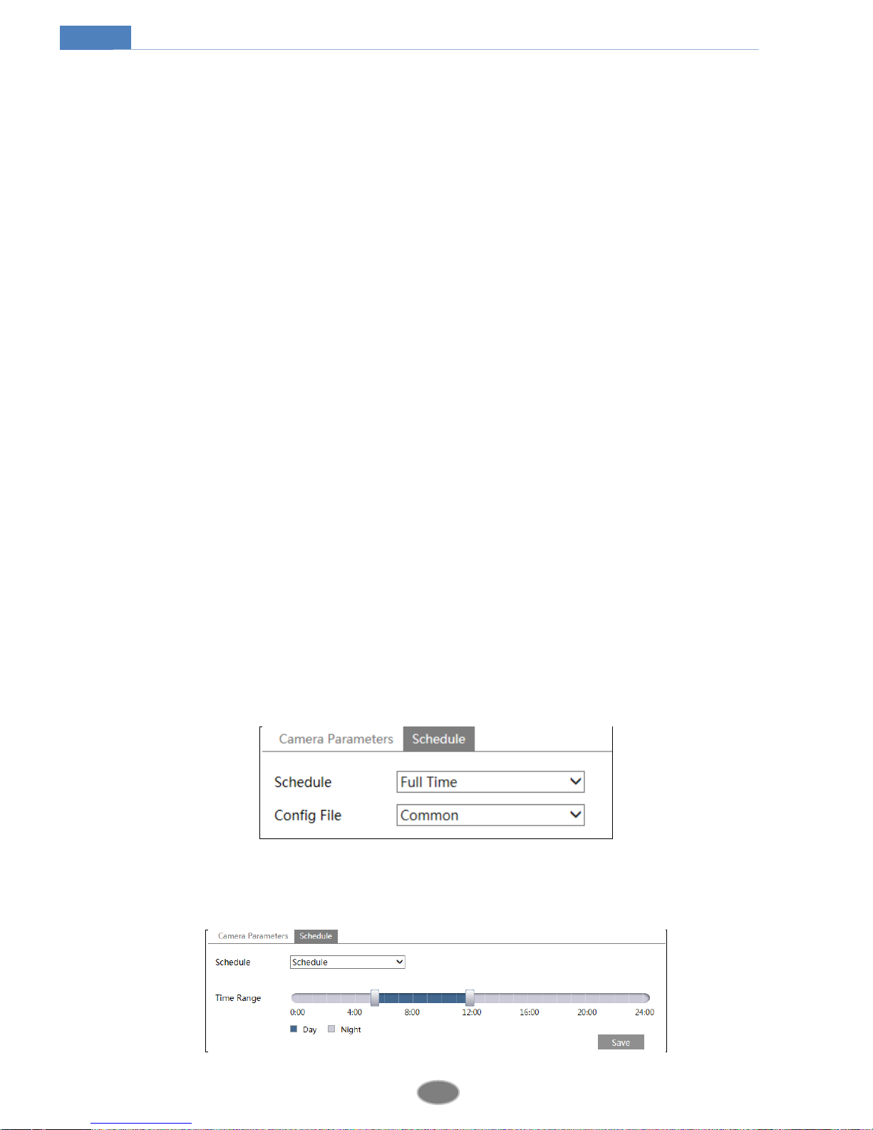
Schedule Settings of Image Parameters:
Click “Schedule” tab as shown below.
You may set full time schedule for common, day, night mode and specified time schedule for
day and night. Choose “Schedule” in the drop-down box of schedule as shown below.
17
Network Camera User Manual
Drag “ ” icons to set the time of day and night. Blue means day time and blank means night
time. If the current mode of camera parameters is set to schedule, the image configuration
mode will automatically switch between day and night according to the schedule.
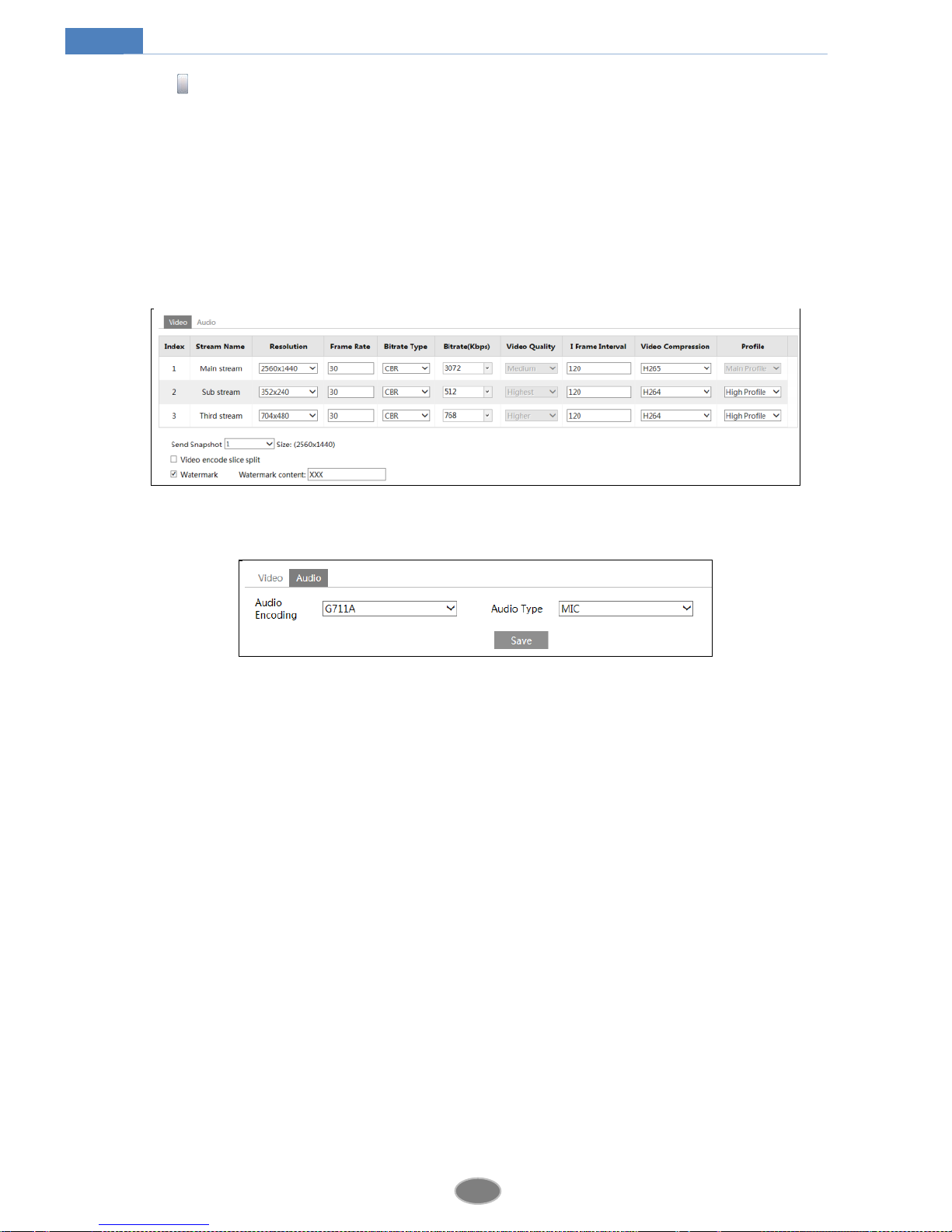
4.2.2 Video / Audio Configuration
Go to ImageVideo / Audio interface as shown below. In this interface, you can set the
resolution, frame rate, bitrate type, video quality and so on subject to the actual network
condition.
Click “Audio” tab to go to the interface as shown below.
Three video streams can be adjustable.
Resolution: The higher the resolution is, the clearer the image is.
Frame rate: The higher the frame rate is, the more fluent the video is. However, more storage
room will be taken up.
Bitrate type: Including CBR and VBR. CBR means that no matter how changeable the video
resources are, the compression bitrate keeps constant. This will not only facilitate the image
quality better in a constant bitrate but also help to calculate the capacity of the recording.
VBR means that the compression bitrate can be adjustable according to the change of the
video resources. This will help to optimize the network bandwidth.
Bitrate: Please choose it according to the actual network situation.
Video Quality: When VBR is selected, you need to choose image quality. The higher the
image quality you choose, the more bitrate will be required.
I Frame interval: It is recommended to use the default value. If the value is over high, the
read speed of the group of pictures will be slow resulting in the quality loss of the video.
Video Compression: H264 and H265 are optional. Higher quality of image can be transferred
under limited network bandwidth by using H265 video encoding. However, higher quality of
the hardware is required.
Profile: Baseline, main/high profiles are optional. Baseline profile is mainly used in
interactive application with low complexity and delay. Main/high profile is mainly used for
18
Network Camera User Manual
higher coding requirement.
Send Snapshot: Please select it according to the actual situation.
Video encode slice split: If this function is enabled, you may get more fluent image even
though using the low-performance PC.
Watermark: Check it and input the watermark content. You may see the watermark when
playing back the local record in the search interface, lest the record files is tampered.
Audio Encoding: G711A and G711U are selectable.
Audio Type: MIC and LIN are selectable.
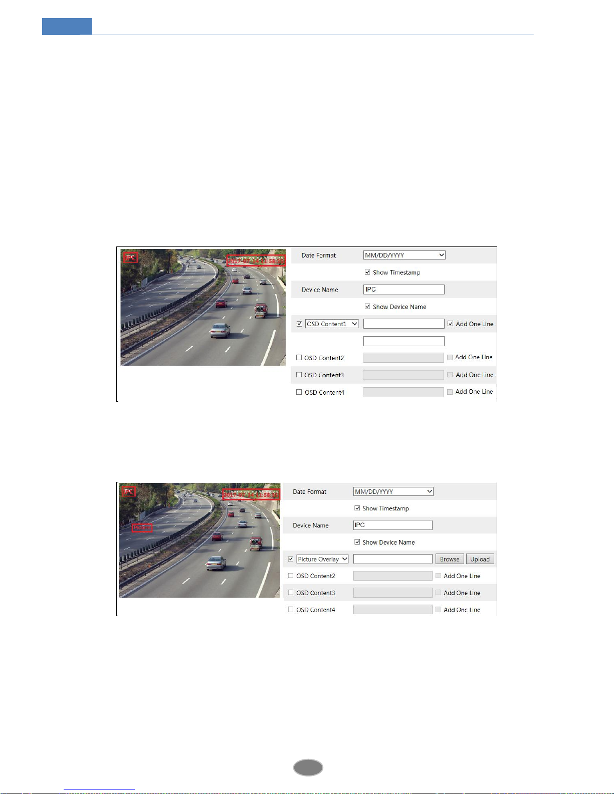
4.2.3 OSD Configuration
Go to ImageOSD interface as shown below.
You may set time stamp, device name, OSD content and picture overlap here. After enabling
the corresponding display and inputting the content, drag them to change their position. Then
click “Save” button to save the settings.
Picture Overlap Settings:
Check “OSD Content1”, choose “Picture Overlay” and click “Browse” to select the overlap
picture. Then click “Upload” to upload the overlap picture. The pixel of the image shall not
exceed 200*200, or it cannot be uploaded.
4.2.4 Video Mask
Go to ImageVideo Mask interface as shown below. You can set 4 mask areas at most.
19
Network Camera User Manual
To set up video mask:
1. Enable video mask.
2. Click “Draw Area” button and then drag the mouse to draw the video mask area.
3. Click “Save” button to save the settings.
4. Return to the live to see the following picture.
Clear the video mask:
Go to video mask interface and then click “Clear” button to delete the current video mask
area.
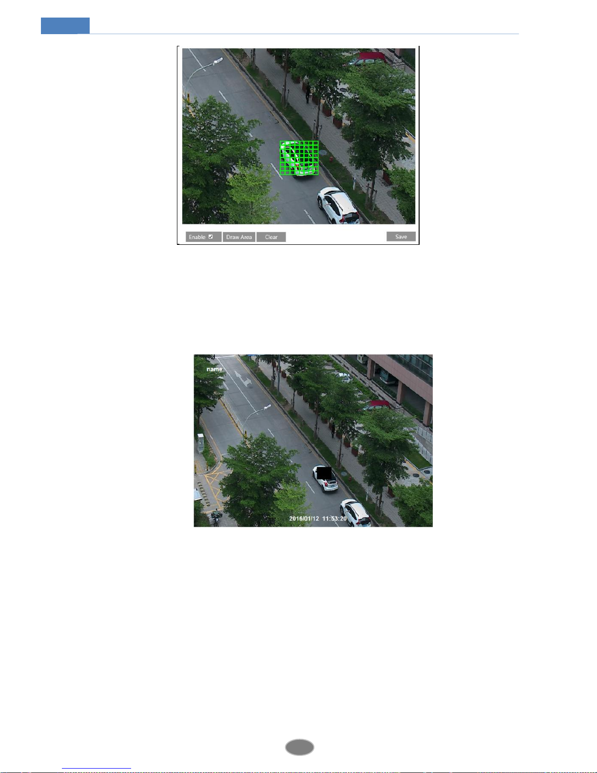
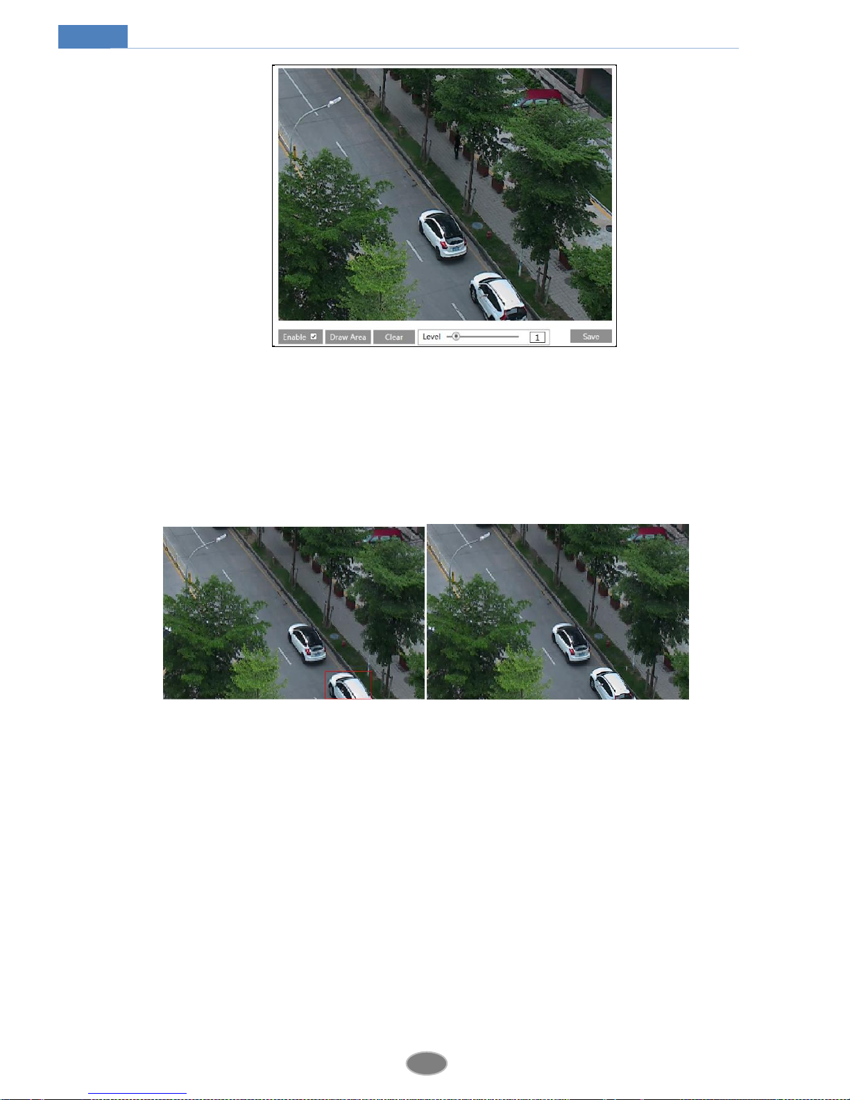
4.2.5 ROI Configuration
Go to ImageROI Config interface as shown below.
20
Network Camera User Manual
1. Check “Enable” and then click “Draw Area” button.
2. Drag the mouse to set the ROI area.
3. Set the level.
4. Click “Save” button to save the settings.
Now, you will see the selected ROI area is clearer than other areas especially in low bitrate
condition.
4.2.6 Lens Control
This function is only available for the model with motorized zoom lens. You may adjust
zoom and focus and choose the focus mode or one key focus.
 Loading...