

Page 1
Parameter Generation and Control, Inc.
Black Mountain, North Carolina
(828) 669-8717
500-1000 CFM Air Handler
460V, 60 Hz
Model #9354-4250
Installation and Operation Manual
Customer
Serial #
Ship Date
Parameter Generation and Control, Inc.
P. O. Box 129 1054 Old US 70 West Black Mountain, NC 28711
(800) 438-5494 (828) 669-6928 FAX
.
.
.
Page 2

PGC Inc. Horizontal 500-1000 CFM June 2006
Parameter Generation and Control, Inc.
2
Page 3

PGC Inc. Horizontal 500-1000 CFM June 2006
Inspection........................................................................................................................ 4
Installation....................................................................................................................... 4
Plumbing..................................................................................................................... 4
Electrical Connections................................................................................................7
Electrical Connections................................................................................................8
Operation......................................................................................................................... 9
Turning the Chamber Off and On............................................................................... 9
Process Variable Display.......................................................................................... 10
Adjusting Set Points.................................................................................................. 10
Operation After Loss of Power................................................................................. 10
Fault Displays ........................................................................................................... 11
Control Modes .......................................................................................................... 12
Specifications, 500-1000 CFM..................................................................................... 13
Replacement Parts, 500-1000 CFM.............................................................................. 14
Appendices
Appendix A – Technical Information
Appendix B – SmartPad™ Operation Manual
Appendix C – Diagrams
Appendix D - Manuals for Accessory Equipment
Parameter Generation and Control, Inc.
3
Page 4

PGC Inc. Horizontal 500-1000 CFM June 2006
Inspection
If the equipment is damaged upon receipt, immediately request the delivering carrier to
perform an inspection and prepare a report. All claims for damage must be made against
the delivering carrier. Report the nature and extent of the damage to PGC, 828-669-8717,
and include instrument serial and catalog numbers to facilitate repair or replacement.
Installation
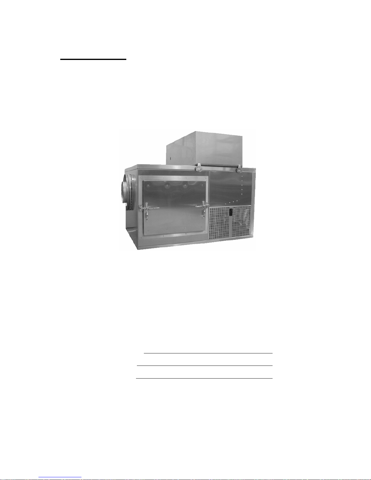
The 500-1000 CFM Conditioner was designed to be located adjacent to or on top of the
chamber to be conditioned. Allow at least 36 inches on the right side and front of the unit
for service. The location must be convenient to an adequate process water supply, drains
and electrical power. The conditioner must be reasonably level for proper water level
control.
Electrical power and water must be connected to this unit prior to operation. The required
voltage and current are listed on the nameplate located on the unit. The sump drain may
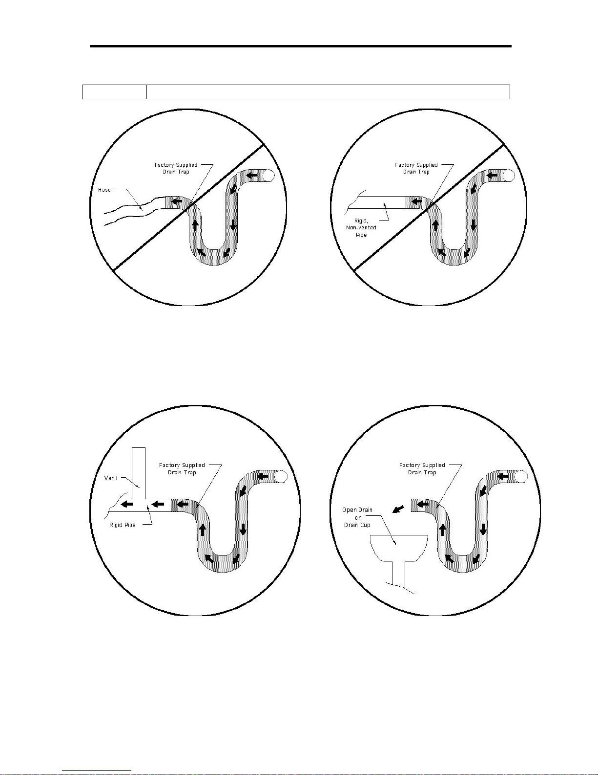
be connected directly to a facility drain, but the condensate drain must be connected to an
open (vented) trapped drain (see Figure 3) to ensure that backpressure on the facilities’
drain does not prevent proper drainage.
Note
The condensate drain has been supplied with a copper trap.
Plumbing
To prevent damage to the water pump and water heater, the unit must not
CAUTION
be operated until water is supplied to the unit and the sump has filled to the
proper level.
Process Water Supply Specifications
Units Maximum Typical Minimum
Process Water Pressure PSIG (Bar)
Process Water Daily
Gallons (Liters)
125 (8.6) N/A 5 (0.35)
5.0 (19) 1.5 (5.7) 0 (0)
Consumption
Condensate Production
Gallons (Liters)
5.0 (19) 1.5 (5.7) 0 (0)
per Day
Sump Water Volume Gallons (Liters)
15 (57) 15 (57) 6.6 (25)
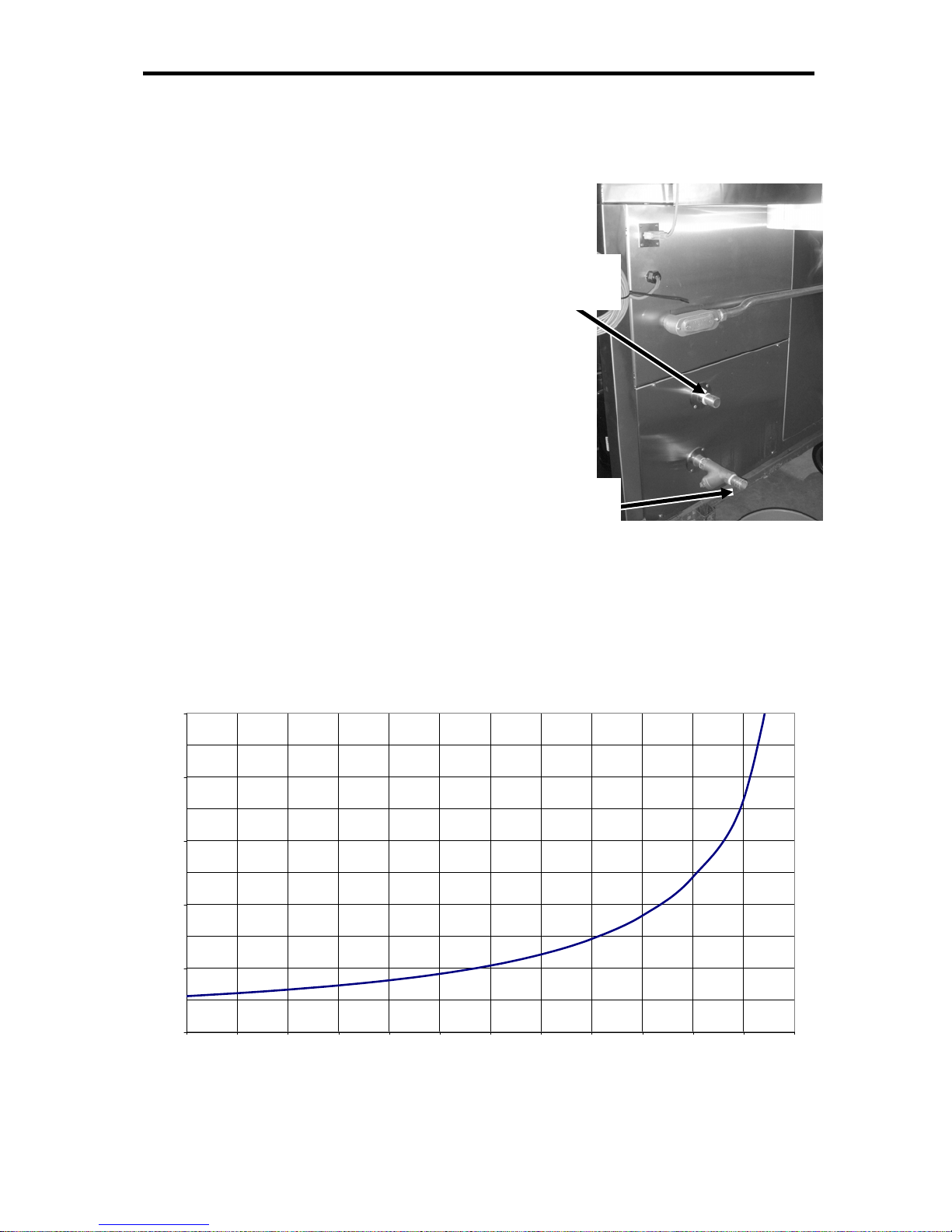
Process Water Inlet
Connect a clean water supply line through an external customer-supplied hand valve to
the Process Water Inlet connection on the rear of the conditioner; this is a ½” male NPT
connection.
Parameter Generation and Control, Inc.
4
Page 5
PGC Inc. Horizontal 500-1000 CFM June 2006
Condensate Drain
Connect the condensate drain to an open (vented) trapped external drain. This drain is a
¾” female copper sweat connection on the rear of the conditioner.
Sump Drain
Connect the sump drain to a facilities
drain. This drain does not require a trap.
This drain connection is made to the ¾” ¼
turn ball valve, supplied on the rear of the
Coolant Water
Outlet
conditioner.
Coolant Water Supply and Return
If the refrigeration system is equipped
with a water-cooled condenser. Connect
coolant water to the condenser inlet
connection on the rear of the chamber
cabinet. Connect the coolant water return
line to the coolant water outlet connection.
Coolant Water
Inlet
Coolant flow requirements will vary based
on the operating conditions of condensing
units, as the temperature of the coolant fluid.
The following graph indicates the maximum
Coolant Water Connections
500-1000 CFM
coolant flow requirements for the condenser.
Maximum Condensor Water Flow Requirements
5.00
4.00
3.00
2.00
Gallons Per Minute
1.00
0.00
45 50 55 60 65 70 75 80 85 90 95 100 105
500-1000 CFM
Entering Water Temperature (Degrees F)
Parameter Generation and Control, Inc.
5
Page 6

PGC Inc. Horizontal 500-1000 CFM June 2006
Filling the sump
To fill the conditioner with water, ensure
that the sump drain valve is closed and open
the customer-supplied external water inlet
valve. When the sump is filled to the proper
Process Water
Inlet
level, a mechanical float valve will
automatically shut off the flow and maintain
the proper water level during operation. The
float valve is preset at the factory to
maintain the proper level (1/2” above the
evaporator tubing); to change the water
Condensate
Drain
level, adjust the angle of the float arm
slightly.
A low-water safety switch is located in the
front, left corner of the sump. This switch
will open when the water level is too low for
safe operation of the pump and water heater.
When the water level is correct, the float
Plumbing Connections
Service
Drain
switch will close and allow the controller to
resume operation of the unit.
The water fill valve float may be padded to prevent damage during
CAUTION
shipping. Remove the padding before connecting the water supply to the
inlet.
NOTE
The conditioner will not operate until the low water level safety is satisfied.
Parameter Generation and Control, Inc.
6
Page 7
PGC Inc. Horizontal 500-1000 CFM June 2006
CAUTION
Do not connect the drain connection to an un-vented drain.
NOR
Ensure that the drain connection is vented, as shown below.
OR
“Open” (Vented) Drain Connections
Parameter Generation and Control, Inc.
7
Page 8

PGC Inc. Horizontal 500-1000 CFM June 2006
Electrical Connections
Turn all electrical switches, circuit breakers, and motor starter protectors
CAUTION
(MSPs) off to prevent accidental starting of equipment when power is
connected.
Determine voltage and current requirements of equipment before making
NOTE
electrical connections. This information is on a data plate attached to the
machine.
Connect the air handler in accordance with all applicable codes, using a customersupplied disconnect device.
The SmartPad™ user interface and the optional circular chart recorder can be located
remote from the air handler. Typically, the controller is located on the front of the
chamber to be controlled. These components are usually disconnected for shipment and
must be re-connected prior to operation. Refer to the attached wiring diagrams for reconnection information.
The SmartPad™ user interface interconnect cable has a maximum voltage
NOTE
of 24VDC. Refer to local codes to determine the proper conduit
requirements for the control cable.
The optional circular chart recorder can be powered by 24VDC or
120/230VAC. Refer to the wiring diagrams or the data plate on the
recorder for more information.
CAUTION
The compressor and blower will not
operate properly and may be damaged if
permitted to run backward. After the
Conditioner has filled with water and is
operating, observe the rotation of the
blower through the air bypass damper.
Ensure that the blower is turning as
indicated in the diagram below. If
necessary, turn off the wall disconnect and
interchanging any two phase wires at the
wall disconnect or of the line connection terminals. Exchanging
phases at this point will reverse the rotation of all 3-phase motors.
Parameter Generation and Control, Inc.
8
Page 9
PGC Inc. Horizontal 500-1000 CFM June 2006
Operation
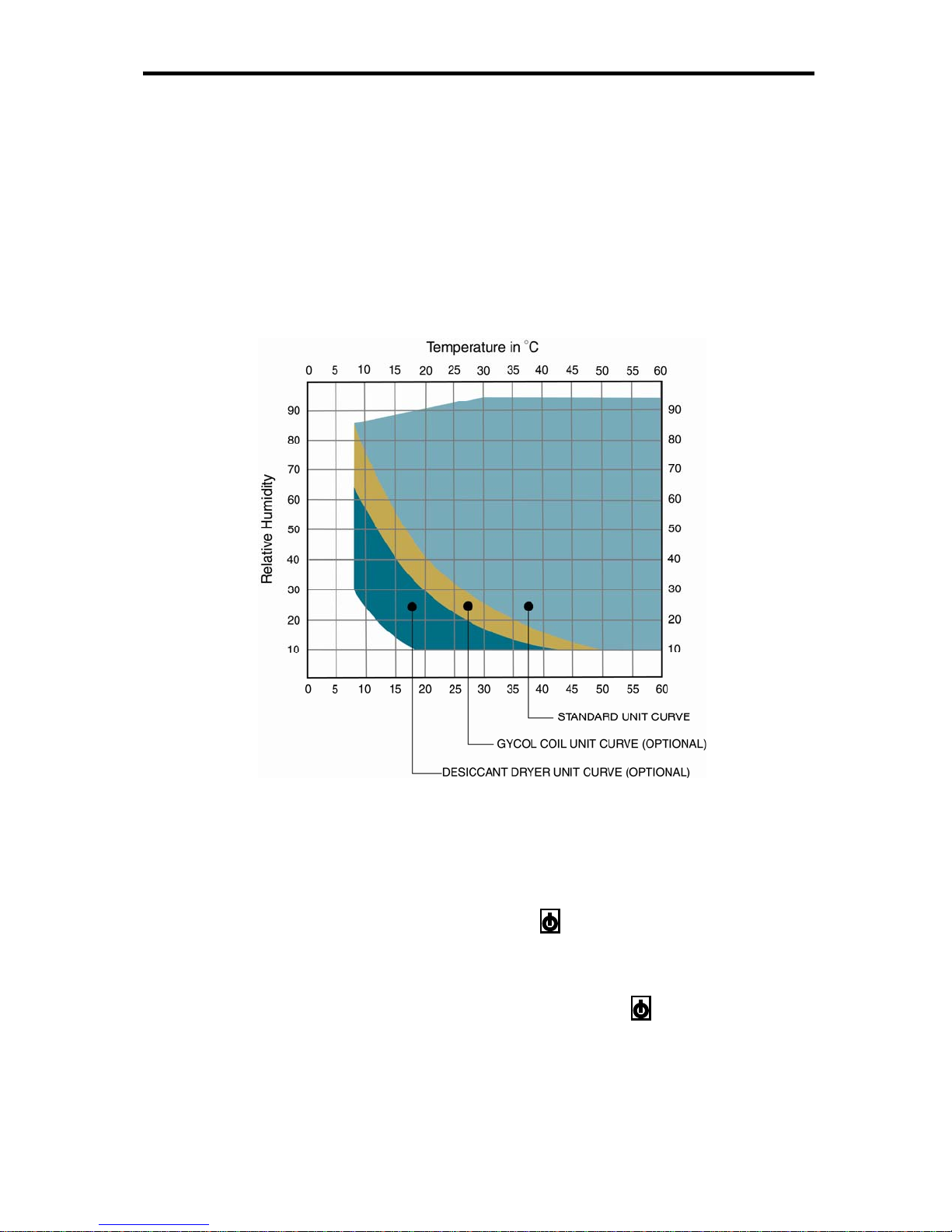
The 500-1000 CFM Conditioner is a self-contained conditioner designed to control drybulb temperatures over a range of 7°C - 60°C (44.6ºF - 140ºF), dependent upon the size
and construction of the test chamber. The dry-bulb temperature is held to ± 0.2°C and
relative humidity constancy to ± 0.5% with dew points above 5°C (41°F).
The SmartPad™ may be remotely mounted; refer to the PGC SmartPad™ section at the
rear of this manual for instructions.
Operating Range
Turning the Chamber Off and On
When the chamber is energized and the Standby key has been pressed, the system
should begin to operate and control the temperature and humidity in the chamber at the
set points entered into the SmartPad™ user interface.
The SmartPad™ user interface is configured with a Standby key located in the lower
right corner of the keypad. Pressing this key will disable the system and place the
controller in a Standby mode. The SmartPad™ display will indicate:
Parameter Generation and Control, Inc.
9
Page 10

PGC Inc. Horizontal 500-1000 CFM June 2006
STANDBY MODE
Press the ON/OFF key
to energize the system
When the system is in Standby mode, it can be energized by pressing the Standby key
Process Variable Display
The Process Variable screen is the first screen that will be displayed when the conditioner
is energized. This screen will display the measured process variables and will allow
access to the other screens in the SmartPad™.
The bottom line of the SmartPad™ display is a label for the four function keys on the key
pad. This label will vary from screen to screen to reflect the action of each of the function
keys.
Refer to the SmartPad™ manual in the appendix for a complete listing and discussion of
available screens.
Adjusting Set Points
In the Process Variable screen, pressing the SP function key will access the Set Point
screen. The Set Point screen will allow the user to enter the desired air temperature and
relative humidity set points for the chamber.
The SmartPad™ has no ENTER key. In order to enter a value in any field
NOTE
all digits must be entered. For example, to enter 25.0°C air set point you
must press “2”, “5” and “0”. When the field has been filled and the data has
been entered, the cursor will jump back to the beginning of the field.
Operation After Loss of Power
If power is removed from the conditioner, the controller will resume operation in the
same mode when power is regained. For instance, if the SmartPad™ was in Standby
mode when power was lost, it will be in Standby mode when power is restored. If the
SmartPad™ was operating and controlling the chamber, it will return to that mode of
operation.
Parameter Generation and Control, Inc.
10
Page 11

PGC Inc. Horizontal 500-1000 CFM June 2006
The SmartPad™ is not equipped with a battery backup.
NOTE
All set points, tuning values and ramping profiles are stored in non-volatile
memory and will be permanently stored in the SmartPad™.
If power is removed from the controller it will resume operation when
power is restored.
In Steady State set point mode the controller will resume operation at the
previous steady state set points.
In Programmable set point mode the controller will resume operation at
exactly the same segment and time remaining in that segment if the
duration of the power loss is less than approximately 20 minutes. If the
duration of the power loss exceeds approximately 30 minutes the
controller will re-initiate the program according to the loop parameters
defined in the INIT screen.
Fault Displays
If the system encounters a temperature, low-water, remote on/off switch, or refrigerant
pressure fault, the system will shut down and the SmartPad™ will indicate the fault that
has occurred. The SmartPad™ will continue to indicate that the fault exists, and will
indicate if/when the fault has cleared.
If the fault has been cleared, the system can be re-energized by pressing the Standby key
. If the fault has not cleared, the source of the fault must be determined and corrected
before the system can be re-energized.
Some faults will clear automatically and others will require user
NOTE
intervention.
Regardless of the fault clearing mechanism, the user must press the Standby
key in order for the conditioner to resume operation.
Parameter Generation and Control, Inc.
11
Page 12

PGC Inc. Horizontal 500-1000 CFM June 2006
Control Modes
The PGC conditioning system offers four modes of temperature and humidity control.
1. Cascade Temperature Mode
This is the most commonly used mode because the user specifies only the desired
air temperature and relative humidity (Rh) level in the chamber. The temperature
of the water spray controls the dew point of the discharge air and the water
temperature is adjusted in order to achieve desired humidity level. The air is then
re-heated to the desired temperature before returning to the test chamber. This
allows the system to respond to load variations while retaining the basic stability
of a spray system.
2. Two-Temperature Mode
In this mode, the user establishes the desired air and water temperatures that are
required to produce the desired relative humidity level, as determined by a
psychometric chart. The Two-Temperature mode can be used when operating the
very edges of the system capabilities.
3. Slow Damper Mode
This mode is similar to Cascade mode with the difference being that the air
bypass damper control loop and the air heater control loop have been separated.
In this mode the damper is moved slowly and its final position is when the desired
percentage of air heat output is achieved. The desired percentage of air heat is
determined by the user in the tuning parameters (Manual Adjust) section of the
controller. In some situations, slow damper mode can be applied to improve
energy efficiency or extend the operating range of the system. Typically, slow
damper mode is most effective when the system is operated at a single condition
as it will often require manual tuning adjustments for proper operation at multiple
set points.
4. Dry Mode
This mode is required to control dew points below 4°C. In this mode, all water is
removed from the spray chamber and an optional desiccant dryer is used to
control humidity. Although this mode is accessible in SmartPad, it is nonfunctional unless the system is equipped with a desiccant dryer.
Parameter Generation and Control, Inc.
12
Page 13

PGC Inc. Horizontal 500-1000 CFM June 2006
Specifications, 500-1000 CFM
Voltage-------------------------------------------------------------------------------- 460V~
Frequency----------------------------------------------------------------------3ph, 60 hertz
Current------------------------------------------------------------------------------ 8.8 FLA
Circuit Capacity (Max / Min)--------------------------------------------------30A / 12A
Heater, Water ------------------------------------------------------------------- 1800 watts
Heater, Air (Two, 1500 watt) ------------------------------------------------- 3000 watts
Refrigerant-------------------------------------------------------------R-404a, 96 Ounces.
Process Water Pressure, (Max/Min) ------------------------------------------125/5 psig
Weight Net --------------------------------------------------------------------------1000 lb.
Weight Shipping--------------------------------------------------------------------1400 lb.
Temperature Range -------------------------------------------------------------7° to 60°C
Relative Humidity Range----------------------------------------------------10% to 95%
1
Temperature Constancy (control) ------------------------------------------------ ± 0.2°C
Rh Constancy (control) ----------------------------------------------------------± 0.5%
1
Minimum Rh is limited by a minimum dew point of 5°C (41°F) for standard Spray
Mode. For example:
Air
Max. Rh Min. Rh
Temperature
10°C (50°F) 88% 70%
25°C (77°F) 93% 32%
40°C (104°F) 95% 17%
> 50°C
95% 10%
(122°F)
Parameter Generation and Control, Inc.
13
Page 14

PGC Inc. Horizontal 500-1000 CFM June 2006
Replacement Parts, 500-1000 CFM
Description Mfg. / Supplier Mfg./Supplier # PGC #
ACE Master Micro Controller PGC ACE 503g N/A
ACE4 Controller Assy. PGC OEM 6000-1559
ACE4 Power Supply Meanwell PS45-24 1607-0024
Circuit Breaker,1 Pole, 2AMP Siemens 5SX2102-8 0426-1020
Circuit Breaker,2 Pole, 2AMP Siemens 5SX2202-8 0426-2020
Compressor Copeland CS14K6E-TFD-230 1510-0298
Contactor Siemens 3RT1025-1BB40 0419-0948
Damper Drive Motor Actuator Belimo
OEM
1608-
0916A
Door, Spray Chamber, Inner PGC N/A 6000-0303
Door, Spray Chamber, Outer PGC N/A 6000-0392
Evaporator Coil, 5/8 OD x .032 wall Super Radiator Co. OEM 1244-0066
Filter Bag,5 Micron, Polyester McMaster-Carr 9316T22 0215-1800
Fuse, Door Heat 5A Bussman FNM5 0409-0123
Gasket, Return Duct Transition
Refrig. Hardware 47-131 1604-0101
Box, 140”
Gasket, Spray Chamber Inner
Refrig. Hardware 47-131 1604-0101
Door, 95”
Gasket, Spray Chamber Outer
Refrig. Hardware 47-131 1604-0101
Door, 95”
Gasket, Supply Duct Transition Box Refrig. Hardware 47-131 1604-0101
Heater, Air Vulcan OEM 0416-0508
Heater, Water Watlow OEM 0416-0599
Hour meter, UV Durant E42DIR48230 0215-2821
HygroClip Connector and Cable,
5 meters, amplified analog, 0ºC to
PGC MOK-05-XX-005V-1-
DIO
1636-0159
100ºC
HygroClip Micro Controller PGC Hygro 503 N/A
HygroClip T/Rh Transmitter,
PGC OEM
1608-0865b
Full-Range Calibration
HygroClip T/Rh Transmitter,
PGC OEM
1608-0865a
Single-Point Calibration
HygroClip T/Rh Transmitter, Un-
Rotronic HygroClip S 1608-0865
calibrated
HygroPalm Calibration Cable PGC AC1620-modified 1609-0866
HygroPalm Calibrator Rotronic HygroPalm 2 1609-0865
Latches, Access Panel Southco 62-43-251-3 1008-0080
Latches, Inner Doors Southco OEM 1001-0082
Latches, Outer Doors McMaster-Carr 5481K19 1009-1017
Mist Eliminator PGC N/A 5000-0135
Motor Protector Siemens 3RV1021-1KA10 0427-1250
Motor Protector Siemens 3RV1021-0GA10 0427-0063
Parameter Generation and Control, Inc.
14
Page 15

PGC Inc. Horizontal 500-1000 CFM June 2006
Description Mfg. / Supplier Mfg./Supplier # PGC #
Motor Protector Siemens 3RV1021-1BA10 0427-0200
Motor, Blower Continental Fan RO-TMK280-2-34 1602-0199
Pump March TE5.5CMD 1619-0091
Refrigeration Dryer, Filter Sporlan CW-165S 0215-0887
Relay , Solid State, Door Heat Omron G3NE-210T-US 0416-0414
Relay, Solid State, 4-28 VDC Continental RVDC/6V25 0416-0403
Sensor , Door Jamb Temperature JMS Southeast OEM 1607-0652
Sensor ,Water Temperature JMS Southeast 3ESCK6BZZ3120JYTA1619-0862
SmartPad™ controller PGC OEM 1607-1100
SmartPad™ Micro Controller PGC Spad 503D N/A
Spray Nozzle Spraying System NO. 1/4A-SS5-15. 1612-0201
Stepper Micro Controller PGC Step 503 (SDR3) N/A
Strainer, Bronze “Y” McMaster-Carr 43935K24 0215-0904
Supply Duct Transition, 10” Round PGC N/A 5000-1389
Surge Suppressor Siemens 3RT1936-1TR00 0419-0891
Switch, Float Gems LS1750-192-908 0421-0060
Switch, Hi-Lo Refrig Pressure Copeland 085-CP2M-7K 0423-0683
Thermostat, Safety Thermtrol TS-120SR 30F-240F 1636-0223
Timer, Chamber Light Intermatic FF60MC 0419-0355
Transformer Micron B100MBT713XK 0419-0326
UV Lamp Severn Trent Water 5340UD 0215-2825
UV Lamp Power Supply Severn Trent Water 20697UD 0215-2831
UV Lamp Quartz jacket Severn Trent Water 2450UD 0215-2824
UV Plastic Support PGC OEM 0215-2826
Valve, Expansion, Body Danfoss 068U2287 0215-0872
Valve, Expansion, Cartridge Danfoss 068U1037 0215-0777
Valve, Hot Gas Temp Control Sporlan SDR-3-20-S 0215-0873
Valve, Sump Float Hawkeye Steel
UFV600 0209-0050
Products
Parameter Generation and Control, Inc.
15
Page 16

Parameter Generation and Control, Inc
Precise Humidity Control
Notes:
________________________________________________________________________
________________________________________________________________________
________________________________________________________________________
________________________________________________________________________
________________________________________________________________________
________________________________________________________________________
________________________________________________________________________
________________________________________________________________________
________________________________________________________________________
________________________________________________________________________
________________________________________________________________________
________________________________________________________________________
________________________________________________________________________
________________________________________________________________________
________________________________________________________________________
________________________________________________________________________
________________________________________________________________________
________________________________________________________________________
________________________________________________________________________
________________________________________________________________________
www.humiditycontrol.com
sales@humiditycontrol.com
(800) 438-5494
Fax (828) 669-6928 (828) 669-8717
Black Mountain, North Carolina
Page 17

PGC, Inc 500-1000 CFM Air Handler May 2006
Appendix A
System Construction ................................................................................................................... 2
Theory of Operation.................................................................................................................... 3
Description of Operation............................................................................................................. 4
Measurement of Test Chamber Conditions ............................................................................ 4
Air Flow.................................................................................................................................. 4
Water Flow ............................................................................................................................. 5
Temperature Controls ............................................................................................................. 5
Description of Circuitry .............................................................................................................. 7
Safety Devices............................................................................................................................. 9
Troubleshooting ........................................................................................................................ 12
Operating Range of the System. ........................................................................................... 12
Water Temperature ...............................................................................................................12
Air Temperature.................................................................................................................... 13
Water Level .......................................................................................................................... 13
Rh Control ............................................................................................................................ 14
Maintenance .............................................................................................................................. 15
Preventive Maintenance Schedule........................................................................................ 15
Automatic Damper Motor Adjustments ............................................................................... 18
Calibration ............................................................................................................................ 18
Calibration ............................................................................................................................ 19
Calibration, Air/Rh ............................................................................................................... 19
Water Temperature Calibration ............................................................................................ 22
Appendix A A-1
Page 18

PGC, Inc 500-1000 CFM Air Handler May 2006
SYSTEM CONSTRUCTION
The 500-1000 CFM Conditioner consists of four main sections:
1. Conditioning Compartment: spray bypass damper, blower, spray eliminators, spray
jets, water sump, low water level safety float switch, process water float valve, stirring
jet, evaporator coil, and particulate filter
2. Mechanical Compartment (side access panels): refrigeration condenser, compressor,
receiver, , high- and low-pressure safety switches, filter/dryer, hot gas bypass valve,
water pump, water heater, water RTD, Programmable Logic Controller (PLC), and power
panel with terminal strips, circuit breakers, motor starter, and contactors
3. Conditioner Exterior: sump drain valve, air bypass damper actuator, UV filter, and air
temperature safety thermostat.
4. Control Enclosure: SmartPad™ user interface and optional chart recorder.
The unit is sturdily constructed, with a stainless steel interior and exterior, and insulated door
with heavy refrigerator-type latches and vapor-resistant seals. Double walls separated by
insulation are used around the conditioning chamber. All internal seams are welded to preclude
saturation of the insulation.
The spray tree is a 3” stainless steel tube (spray header) with spray nozzles attached along the
sides, and a clamp on each end for sealing the tube. The clamp on the right end secures a blank
plate against an O-ring gasket. A UV lamp is inserted from the electrical compartment, through
the plate on the left end.
Appendix A A-2
Page 19
PGC, Inc 500-1000 CFM Air Handler May 2006
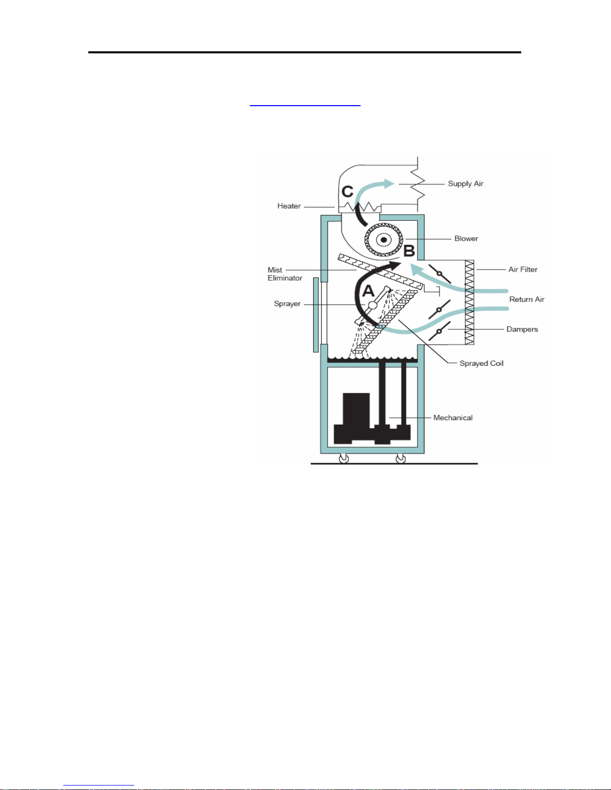
THEORY OF OPERATION
PGC’s method of control is the
same for both reach-in
chambers and conditioning
systems. The environment to be
conditioned is controlled at a
Supply Air
targeted dew point temperature,
and then reheated to the desired
air temperature. This
methodology follows a proven
technique that maintaining a
constant dew point and air
temperature will produce a very
constant relative humidity. The
desired air temperature and
relative humidity or water
Blower
Air Filter
Return Air
Dampers
temperature are set via the
SmartPad™. If equipped with
Sprayed Coil
an optional recorder, it can be
wired to record the actual air
temperature and relative
humidity or water temperature.
Mechanical
The air is cooled by means of a
water spray which constantly
sprays water across the air
stream, saturating the air. A
submerged refrigeration
evaporator coil operates 1°C2ºC (1.8°F-3.6°F) below the
desired dew point and cools the
Figure A-1 - Generic Conditioning Unit
water that is sprayed across the
air stream. The air is then reheated before it is returned to
the test chamber.
NOTE
Dew point is the temperature at which the air can contain no more moisture and
some moisture begins to condense.
A portion of the air can be diverted around the water spray saturator by a bypass damper. If the
air does not pass through the water spray, it will not be cooled; if the air is not cooled, it will not
require as much (if any) air heat to be applied before it is returned to the test chamber. The
amount of air that passes through the saturator, or bypasses the saturator, is determined by the air
temperature control loop.
Appendix A A-3
Page 20

PGC, Inc 500-1000 CFM Air Handler May 2006
DESCRIPTION OF OPERATION
The 500-1000 CFM Conditioner is a self-contained conditioner designed to control dry-bulb
temperatures over a range of 7°C – 60°C (44.6ºF - 140ºF), dependent upon the size and
construction of the test chamber. The dry-bulb temperature is held to ± 0.2°C and relative
humidity constancy to ± 0.5% with dew points above 5°C (41°F).
The temperature of the water spray saturator controls the dew point of the discharge air. When in
Rh Cascade or Slow Damper mode, the water temperature in the saturator is varied slowly in
response to a humidity control system. This allows the system to respond to wide load variations
while retaining the basic stability of a spray system. When in Two-Temperature mode, the user
establishes the air and water temperatures.
M
EASUREMENT OF TEST CHAMBER CONDITIONS
Precise control of temperature and humidity within the test chamber is obtained by accurately
measuring the dry-bulb temperature and the dew point temperature of the air in the test chamber
or the duct. The temperature of the water in the spray chamber controls the dew point
temperature, and is measured prior to the spray nozzles.
When operating in one of the spray modes, the dew point of the air exceeds the water temperature
by approximately 1°C for each 10°C difference between the air and water temperatures. During
the ramp portion of program cycling, the dynamic heat exchange process that takes place makes it
difficult to establish any exact relationship. When operating in the Two-Temperature mode, refer
to the air/Rh/water spray graph provided with the unit for air and water temperatures necessary
for the desired relative humidity.
A
IR FLOW
As the air enters the conditioner through the round, flexible duct connection in the removable top
cover. The process blower, located beneath this cover, will force the air into the conditioning
section. Entering the conditioning section, the air first encounters the by-pass damper; the
damper determines the volume of air that enters the saturator, and the volume that is bypassed
around the saturator. When the damper is fully closed, all of the air is forced through the water
spray. As the air passes through the water spray, it is saturated and cooled, nearly to the water
temperature. This method provides a stable dew point for the air as it leaves the saturator section.
The chilled and saturated air then passes through the water droplet eliminator to remove any free
moisture that may be present. The air then continues over the dry-bulb heaters, where it is heated
to the desired chamber air temperature (without affecting the dew point) and is returned to the
chamber through the round, flexible duct connection on the left end of the conditioner.
When the damper is fully open, most of the air bypasses the water spray and travels directly to the
air heaters. The bypassed air is then mixed with any air that traveled through the saturator section
and then returns to the test chamber. The spray bypass damper will be automatically positioned
by the actuator operating on a control signal derived from the duty cycle of the air heater. The
position of the damper can range from 0% to 100% open.
The dew point of the air stream is controlled even when most of the air is bypassed around the
water spray saturator. The air bypass damper is not 100% efficient, allowing some air to enter the
water spray saturator even when closed.
Appendix A A-4
Page 21

PGC, Inc 500-1000 CFM Air Handler May 2006
In Slow Damper mode, the position of the damper is load dependent; the damper
will change slowly to achieve the desired conditions. The damper will also change
NOTE
position in order to compensate for droop or overshoot in the air temperature
control loop.
W
ATER FLOW
The water pump is located in the right section of the cabinet (accessible through the front or side
access doors). The water is picked up by the pump and heated, and then forced across the water
temperature sensor (100Ω platinum RTD) and into the spray header in the spray chamber. The
spray header is situated to spray water across air stream. The remainder of the water passes
through the particulate filter to remove debris.
T
EMPERATURE CONTROLS
The water temperature is sensed immediately prior to entering the spray headers, and the air &
humidity are measured by the HygroClip™ T/Rh transmitter that is located in the air stream.
The air heaters are positioned in the air-stream path between the chamber and the saturator. The
amount of heat applied is controlled by the dry-bulb control system with the sensing element in
the air stream. The duty cycle (the percentage of heat applied) for the air heater can be accessed
from the SmartPad™.
The water in the sump is cooled by the refrigeration evaporator, and is then sprayed across the air
stream to cool and saturate the air. Since the refrigeration system has a greater capacity than is
needed for most conditions, a hot gas bypass valve is provided to modulate the refrigeration
capacity as required. This valve is automatically adjusted by an actuator operating on a control
signal derived from the duty cycle of the water temperature control loop; the more the hot gas
valve opens, the more the refrigeration capacity is reduced. The relative position of the hot gas
bypass valve is represented by the water heater output percentage: Zero (0%) out is full
refrigeration capacity (hot gas bypass valve closed); one hundred percent (100%) out is minimum
refrigeration capacity (hot gas bypass valve open).
There are four factors that limit or control Water Set Point:
1. Humidity Control Band
Water Set Point will change in order to control Rh. If the measured Rh value is less
than the Rh set point, the Water Set Point will increase in order to increase the Rh by
increasing the dew point. The maximum rate at which the Water Set Point will
change is adjustable; the most common Water Set Point Rate of Change is
0.25ºC/minute (the maximum value). The Water Set Point Rate of Change is
proportional to the deviation from Rh Set Point. For example, if the Rh control band
is +/- 10% and the measured Rh is 10% below Set Point (at 100% of the control
bandwidth), the water Set Point will change at the rate of 0.25°C/minute (the
maximum Rate of Change X 100%). If the measured Rh is 5% below the Rh Set
Point (at 50% of the control bandwidth), the water Set Point will change at the rate of
0.125ºC/minute (the maximum rate of change X 50%).
Appendix A A-5
Page 22

PGC, Inc 500-1000 CFM Air Handler May 2006
2. Water Temperature Set Point Limits
Minimum and maximum Water Set Point limits are factory pre-set in order to prevent
freezing or overheating the pump.
3. Dew Point
Humidity is a function of air temperature and dew point, and the water temperature is
directly related to dew point The controller limits the Water Set Point to 1ºC < Air
Set Point to prevent a runaway temperature control. Without this limit, a runaway
condition could be experienced when operating the unit with a high humidity set
point. Such a setting could cause the water temperature to keep increasing in order to
achieve the humidity set point, which would have the side effect of increasing the air
temperature; this increase in air temperature would increase the capacity of the air to
hold moisture, such that the system would never reach the humidity set point.
4. Measured Water Temp
If the Rh Set Point is set above or below the current Rh control band, the Water Set
Point Rate of Change will automatically maximize to change the water temperature
as quickly as possible. Many variables affect how fast the water temperature will
change, such as the efficiency of the pump, how much water is in the sump, how
often the test chamber is opened, etc. These are beyond the capability of the control
system to measure; however, the controller measures how quickly the water
temperature is actually changing, regardless of the uncontrollable variables. When
the measured Rh is outside of the control band, the Water Set Point is changed
automatically:
Water Set Point = Measured Water Temp + Control Bandwidth
For example, assume that the unit is operating with a Water Set Point of 25ºC and the
water control bandwidth is 5ºC, with the humidity controlling at 50% with the control
bandwidth at 10%. If the Humidity Set Point is set above the upper level of the
control band (>60%), then:
Measured Water Temperature + the Water Control Band = new Water Set Point
In this example, the new water Set Point would be (25ºC + 5ºC=) 30ºC. This will
cause 100% water heater output, and the Water Set Point will continue to increase at
a value equal to the rate that the water temperature is changing. As soon as the
measured humidity value is back within the control band (in this example, when the
measured Rh is 65.01%), the Water Set Point will resume changing at the normal
rate.
Appendix A A-6
Page 23

PGC, Inc 500-1000 CFM Air Handler May 2006
DESCRIPTION OF CIRCUITRY
Although this conditioner utilizes 24 volts DC for the control circuits, some
CAUTION
components require 120 or 460VAC; these voltages can be present even when the
conditioner is not operating.
CAUTION
Power to the unit should be removed at the wall disconnect prior to opening any of
the access panels.
Line voltage is applied to the 24 VDC power supply. The 24VDC power supply provides power
to the Programmable Logic Controller (PLC), the HygroClip T/Rh transmitter, the air bypass
damper actuator, safety devices, and the line contactor.
The PLC has an on-board DC-DC converter that will produce +5VDC for the board-level logic
components. A second DC-DC converter produces +15VDC for use by the SmartPad user
interface, stepper motor, and the RTD amplifiers.
When power is applied to the conditioner, and control circuit breaker(s) are closed, the SmartPad
user interface will be energized. If all of the safety devices are satisfied (pressure switches,
thermostats, float switches, etc.), then the conditioner can be energized by pressing the Standby
key on the SmartPad™ user interface. This will instruct the PLC to energize the line contactor
(1CON).
When 1CON is closed, power is applied to the motor starter protectors (MSPs) and the heater
circuit breaker. If the MSPs are closed, then the compressor, blower, and pump will be energized.
If the heater circuit breakers are closed, then the air and water heaters will be enabled. The
operation of the air heaters and water heater is controlled by the PLC; the PLC determines the
duty cycle (On time verses Off time) for each of the heaters, based on the requirements of each
temperature control loop. The PLC will open and close digital outputs that will control the input
signals to solid-state relays, which will apply power to the respective heater based on the
respective control loop. An LED on each relay will indicate the On or Off status of that particular
heater control loop.
The UV filter will also be enabled by the control circuit breaker(s). Any time power is applied to
the conditioner, the control circuit breakers are closed, and the unit is operational (i.e. 1CON is
closed), the UV filter should be energized.
On initial power up, the PLC will determine the hot gas bypass valve position by driving the
stepper motor to fully close (0% output) the hot gas bypass valve in order to “zero” the valve.
This involves driving the motor past the full closed position; the valve will be seated against the
full closed stop but is not damaged by this over driving maneuver. Bumping the valve against the
full-closed stop can correct for any “lost steps” or accumulated errors that could occur over time
due to the constant reversal of the stepper motor.
During normal operation, the position of the hot gas valve is based on the output percentage of
the water temperature control loop. This output percentage is translated into a percentage of
“open” value for the stepper motor. The PLC converts this percentage open value into a step
count that will position the valve accordingly. When the valve is adjusted to the desired position,
the PLC will cease to step the motor, and the motor will maintain its current position.
Appendix A A-7
Page 24

PGC, Inc 500-1000 CFM Air Handler May 2006
The position of the air bypass damper is determined by the PLC based on the air output
percentage. The input to the damper actuator is a frequency modulated (FM) square-wave signal.
The damper will be positioned based on the frequency of the FM signal. A yellow LED on the
PLC indicates the duty cycle. Zero percent (0%) air heat output will produce a 0.59 second On
time pulse, which instructs the damper to move to the full spray position. One hundred percent
(100%) air heat output will produce a 2.93 second On time pulse, which instructs the damper to
move to the full bypass position. An On time between 0.59 seconds and 2.93 seconds will
produce a proportional response in the damper position.
The water temperature is measured using a positive-coefficient 100Ω Platinum RTD temperature
sensor. This sensor consists of a very thin Platinum wire that is wound around a ceramic core. As
the temperature of this wire increases, the resistance of the Platinum element increases linearly.
This resistance is placed in a bridge network to produce a linear voltage proportional to the
change in temperature. This voltage is then converted to a digital value that can be used by the
PLC by and the A/D converter.
The air temperature is also measured using a 100Ω RTD located in the HygroClip T/Rh
transmitter. A circuit in the HygroClip converts this RTD input to a digital signal that is
transmitted to the PLC using a single-wire serial interface. The PLC receives this digital signal
and converts it to a digital value that the PLC can use in its calculations.
The HygroClip also converts the RTD input into a 0-1VDC analog signal that is scaled so that
0.1VDC = 1°C. This analog signal is applied to an amplifier built into the HygroClip connection
cable, which converts the 0-1VDC signal into a 0-5VDC signal (0-5VDC is required if the analog
signal is transmitted more than 10 feet). The 0-5VDC amplifier can be used to scale the analog
output for different ranges; the most common range is (0-5VDC) = (0°C to 100°C). However,
amplifiers are available for (-30°C to +70°C) and (-40°C to +60°C). This 0-5VDC analog
amplifier is not used by the chamber controller, and is only required when an analog device (such
as a chart recorder) is connected to the system. This analog output is available on the chart
recorder connector of the PLC.
The relative humidity is measured using a thin-film polymer capacitive element that changes
capacitance as moisture is absorbed or given off. The HygroClip T/Rh transmitter will convert
this change in capacitance into a digital value. This digital value is transmitted to the PLC in the
same single-line serial interface as the air temperature measurement. The PLC will decode the
digital value and convert it to a digital value that can be used by the PLC. The HygroClip T/Rh
transmitter will also convert the measured Rh to a 0-1VDC analog output. The same analog
amplifier that is used in the analog air temperature output will convert the 0-1VDC signal to a 05VDC signal. In all instances, the Rh output will be scaled so that 0-5VDC will equal 0-100%
Rh. This analog output is also available at the chart recorder connection on the PLC.
A separate voltage to current converter is installed in the air handler electrical compartment for
both the air temperature and relative humidity. This device will convert the 0-5VDC analog
signal from the HygroClip to 4-20mA. The output will be scaled so that 4-20mA corresponds to
the same temperature or Rh range as the analog signal from the HygroClip (typically this will be
4-20mA = 0-100°C or 0-100% Rh). The 4-20mA signal is provided as an interface to a customer
supplied monitoring device. This converter is equipped with a zero and span calibration
potentiometer that can be field adjusted in order to match the 4-20mA output with the NIST
traceable temperature and Rh output from the HygroClip.
Appendix A A-8
Page 25

PGC, Inc 500-1000 CFM Air Handler May 2006
SAFETY DEVICES
The unit is equipped with several safety devices to guard against serious trouble due to failure of
any components.
Alarm contacts are available on the PLC, which will switch when either of the process variables
is in an alarm condition. The process variables are Air and Water in Two-Temperature mode, or
Air and Rh in any other mode. The alarm type, set points, and time delay are all programmable
from the SmartPad™; and the alarm can be disabled from the SmartPad™; refer to the
SmartPad™ manual for further information. The alarm contact is a single-pole double-throw
(SPDT), Normally Open / Normally Closed, dry contact relay rated at 6 Amps @ 250VAC.
Compressor Internal Overload: The refrigeration compressor is equipped with an internal
thermal protector. If the compressor draws excessive current, the motor windings will overheat. If
the windings overheat, the internal thermal protector will open and the compressor will not
operate. The rest of the chamber will continue to function, although it is not possible to control air
or water temperature unless the compressor is operating. As soon as the internal temperature of
the compressor motor drops to a safe operating level, the compressor will resume operation. This
reset process will normally require about 45 minutes.
Several potential causes of a compressor internal overload include the loss of coolant water flow,
excessive coolant water temperature, clogged coolant water inlet filter, high ambient temperature,
or excessive refrigerant charge, low line voltage, or unusually high ambient temperature.
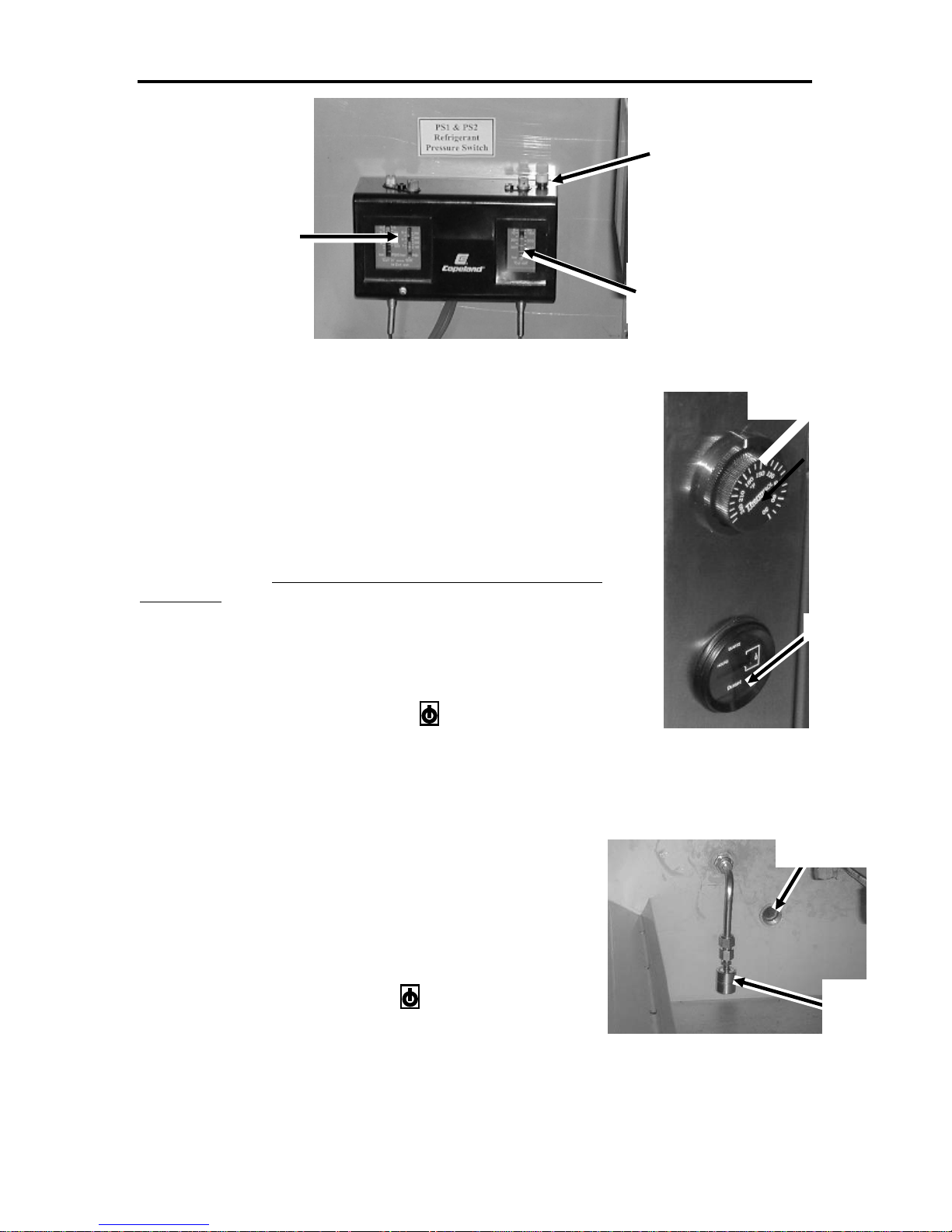
Refrigeration High Pressure Fault: A pressure switch monitors the discharge pressure in the
refrigeration system. This switch is located beside the compressor. If the pressure is allowed to
operate at an excessive level, the compressor will be damaged. If the high-pressure switch opens,
the SmartPad™ will pad indicate “HIGH PRESSURE FAULT SET” and the system will shut
down. The high-pressure switch will automatically reset after the refrigeration discharge pressure
falls below the pressure trip point. When the switch is reset, the SmartPad™ display will indicate
“HIGH PRESSURE FAULT CLEAR”, and the system may be restarted by pressing the Standby
key on the SmartPad™ key
Several potential causes of a compressor internal overload include obstructed or dirty air cooled
condenser, excessive refrigerant charge, low line voltage, or unusually high ambient temperature.
Refrigeration Low Pressure Fault A pressure switch monitors the suction pressure in the
refrigeration system. If this pressure is allowed to operate below a safe level, the compressor may
be damaged. If the low-pressure switch opens, the SmartPad™ will indicate “LOW PRESSURE
FAULT SET” and the system will shut down. The low-pressure fault will automatically reset
when the refrigeration suction pressure rises above the pressure trip point; when this occurs, the
SmartPad™ display will indicate “LOW PRESSURE FAULT CLEAR”, and the system may be
restarted by pressing the Standby key on the SmartPad™ key pad.
Some potential causes of a low-pressure fault include, but are not limited to, low refrigerant
charge, frozen evaporator, or a poor spray pattern.
Appendix A A-9
Page 26
PGC, Inc 500-1000 CFM Air Handler May 2006
r
High Pressure
Reset
Low Pressure
Switch
High Pressure
Switch
Figure A-2 - Pressure Switches
Air Temperature
Safety Thermostat
Over Temperature Thermostat An air over-temperature safety
thermostat has been incorporated into the chamber. The temperature
adjustment for this device is located at the rear of the unit, on the side of
the heater housing. This safety thermostat is designed to protect the
contents of the test chamber from excessive temperature rise in the event
of a system failure. The operator may set this manually to protect the
product under test, normally 2-3°C (5°F) degrees above highest test
temperature. If this thermostat opens due to excessive temperature, the
chamber will shut down and the SmartPad™ user interface will indicate
“TEMPERATURE FAULT SET”. The thermostat will automatically
reset when the temperature inside the chamber drops below the cut-out
temperature. After the thermostat has reset, the SmartPad™ user interface
will indicate “TEMPERATURE FAULT CLEAR”, and the system may
UV Time
be restarted by pressing the Standby key on the SmartPad™ key pad.
Low-Water Safety Switch A low-water level safety float
switch is located in the front left corner of the sump, near the
floor of the sump; this switch will shut down the air handler if the
Figure A-3 – Low Water
Safety Float Switch
Condensate
water level in the sump falls below a safe operating level. If this
float switch opens, the air handler will shut down. The
SmartPad™ user interface will indicate “LOW WATER FAULT
SET”. The float switch will automatically reset when the water
level in the sump returns to a safe operating level. After the
switch has reset, the SmartPad™ user interface will indicate
“LOW WATER FAULT CLEAR”, and the system may be
restarted by pressing the Standby key on the SmartPad™ key
pad.
Blower Motor Thermal Contact The blower motor is
equipped with a contact that will open if the blower motor
Figure A-4 – Low Water
Safety Float Switch
temperature exceeds a safe operating level. If this contact
Appendix A A-10
Drain
Low Water
Safety Float
Page 27
PGC, Inc 500-1000 CFM Air Handler May 2006
opens, the air handler will shut down. The SmartPad™ user interface will indicate “FAN TEMP
FAULT SET”. The thermostat will automatically reset when the blower motor tempeature returns
to a safe operating level. After the thermostat has reset, the SmartPad™ user interface will
indicate “FAN TEMP FAULT CLEAR”, and the system may be restarted by pressing the
Standby key on the SmartPad™ key pad.
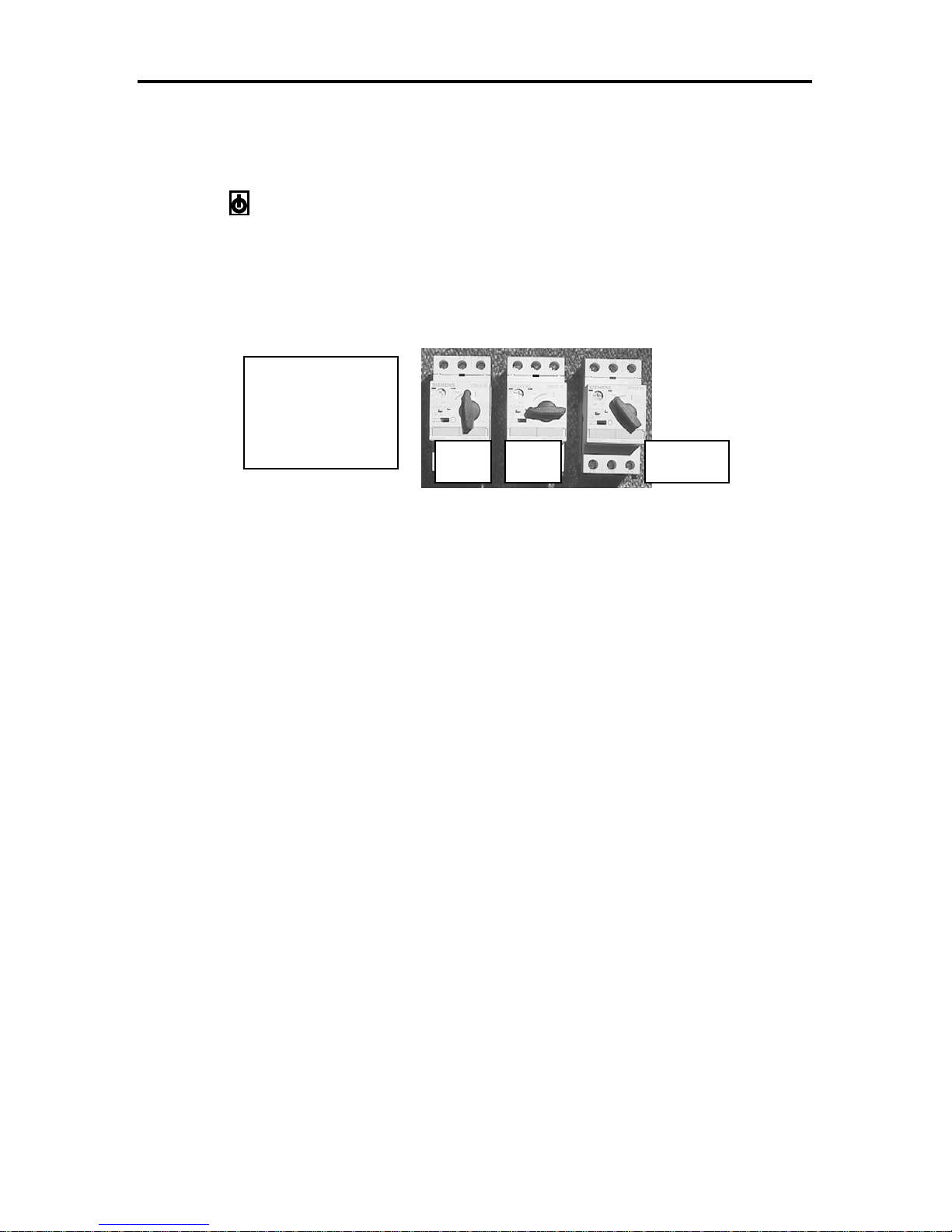
Motor Starter Protector If a motor starter protector (MSP) trips, that component will not
operate. The starter must be reset by turning it to the Off position and then to the On position.
MSPs are used by the process blower, pump, and compressor.
Manual motor
starters in on,
off and tripped
positions
On Off Tripped
Figure A-5 – Motor Starter Protector (MSP)
Appendix A A-11
Page 28

PGC, Inc 500-1000 CFM Air Handler May 2006
TROUBLESHOOTING
CAUTION If the unit has a sight glass / moisture indicator, the hot gas bypass valve may cause
a false indication of low refrigerant charge if the valve is not closed at the time it is
being observed.
PERATING RANGE OF THE SYSTEM.
O
When the system will not control properly there are many potential causes. A basic understanding
of the operation of the system will assist in determining the cause of the problem.
1.) The air temperature will always be greater than the water temperature. Heat is
removed from the air only when the air passes through the water spray.
2.) The water temperature can approach freezing, but it must not be allowed to freeze;
the minimum water temperature is approximately 2.5°C (34.5°F). Since the dew
point is determined by the temperature of the water spray, the minimum dew point
will always be greater than the water temperature, thereby limiting the minimum
achievable dew point.
3.) All blowers, pumps and compressors operate at all times. If any of these items are not
operating, check for motor overload or failure or loose connections.
4.) Ambient conditions will limit operation of the unit. If the room temperature
surrounding the conditioner is too warm or humid, heat cannot be properly rejected
by the air cooled-condenser, affecting the chamber temperature and humidity.
The system will not operate if the low-water level safety switch has opened due to
NOTE
low water level in the sump.
W
ATER TEMPERATURE
1.) The refrigeration system controls the water temperature.
2.) If the water temperature is too high:
a. Check for proper condenser operation.
i. Is the condenser fan(s) operating?
ii. Is the condenser coil clean? During normal operation lint, dirt and debris
will deposit on the entering side of the condenser coil. This will reduce
the cooling capacity of the condenser which will reduce the refrigeration
capacity.
iii. Is the air flow path for the condenser clear? Obstructions such as boxes,
panels are walls can reduce the air flow across the condenser to the point
that it will reduce refrigeration capacity.
iv. Are all of the spray nozzles working? (All of the nozzles should have a
similar spray pattern. If the patterns vary, remove the nozzles and clean
the debris from the orifice)
v. Is the (optional) finned evaporator clean and free of debris?
b. Verify the operation of the refrigeration system
i. When the hot gas valve is fully closed (i.e., water set point is much less
than measured water temperature), the refrigeration sight glass should be
clear. Any bubbles in the sight glass will indicate a low refrigerant
charge.
Appendix A A-12
Page 29

PGC, Inc 500-1000 CFM Air Handler May 2006
ii. Is ice present on the fins of the evaporator (or on the surface of the
submerged tube evaporator)? It is not unusual for the supply lines to the
finned evaporator to be covered in ice; however, it is important that no
ice form on the surface of the coil. Ice on the surface of the coil could
indicate poor water flow or a low refrigerant charge.
iii. Is the refrigeration discharge pressure too high?
1. The air-cooled condenser could be dirty
2. The ambient temperature could be above 95°F
3. The condenser fan(s) may not be working
c. Does the heat load in the chamber exceed the capacity of the system? Since the
heat from the air stream is removed by the evaporator and the water spray, if the
heat load in the chamber is too great, the refrigeration system will become
overloaded if the heat load in the chamber is too great. The first indication of this
will be water temperature, and therefore Rh, that is higher than requested.
A
IR TEMPERATURE
1.) The refrigeration system must have enough capacity to control the water temperature.
If the water temperature is out of control, it is usually not possible to control the air
temperature.
2.) Is the air damper operating properly? Press the clutch release on each actuator two
times to initialize the motor. Observe that the damper moves full travel in both
directions; this may take up to three minutes to complete. If the motor cannot reach
the stops (the Phillips screws at each end of rotation), determine cause of the fault.
3.) Are the air heaters operating properly? Measure the air heater current when the
SmartPad™ indicates 100% air heat output.
4.) Is the airflow restricted or the ductwork leaking? Ordinary A/C ductwork is not
sufficiently vapor tight for an environmental chamber. The duct work must be
capable of holding water for proper vapor barrier.
5.) Is the blower operating efficiently? Inspect the blower wheel for sediment that can
accumulate over time, which decreases the efficiency of the wheel. If this build-up
cannot be removed safely, the wheel must be replaced.
6.) Is the chamber properly sealed?
a. Check the seals around any doors and windows.
b. Are all covers properly installed?
7.) Has the load in the chamber increased?
8.) Check the line voltage. Low line voltage will drastically reduce the wattage of the air
heaters and efficiency of the compressor.
W
ATER LEVEL
1.) The overflow drain must be connected to an open drain; the drain will not work
properly if any backpressure is present.
2.) The overflow drain must functional. If the water level is above the overflow drain
standpipe, the drain is not working properly and the refrigeration system may become
overloaded.
3.) The float valve must maintain the proper water level. The proper water level is high
enough to prevent the pump from cavitating (drawing air into the pump inlet), but
should not be high enough to cause excessive, constant overflow (too much overflow
will overload the refrigeration system)
Appendix A A-13
Page 30

PGC, Inc 500-1000 CFM Air Handler May 2006
H CONTROL
R
1.) The humidity cannot be controlled if the water temperature or air temperature is out
of control; refer to the respective troubleshooting section.
2.) Verify that the air flow through the mist eliminator is unrestricted; restrictions could
permit water droplets to bypass the mist eliminator. If droplets contact the heater, the
droplets will flash into steam and adversely affect the humidity control.
3.) Common Sense. Refer to the air/water/Rh graph supplied. Verify that the measured
air and water temperatures will yield the Rh that is measured. Any gross errors may
help to indicate the source of the problem.
a. Verify the chamber air temperature and/or relative humidity using an
independent sensor. This can be a rough verification just to make sure the air
temperature and Rh measurements are close.
b. Verify the water spray temperature using an independent sensor placed in the
water sump. This can be a rough verification just to make sure the water
temperature measurement is close.
c. If the water spray temperature is considerably colder than should be required:
i. If the ambient dew point is greater than the dew point in the conditioned
space; check for excessive chamber or duct work leakage.
d. If the water spray temperature is considerably warmer than should be required:
i. If the ambient dew point is less than the dew point in the conditioned
space; check for excessive chamber or duct work leakage.
Appendix A A-14
Page 31

PGC, Inc 500-1000 CFM Air Handler May 2006
MAINTENANCE
PGC chambers are designed to be reliable and require minimal maintenance. If the Conditioner is
to be out of service for an extended period, it is advisable to clean the spray chamber interior to
remove contaminants that collected; refer to “Spray Chamber” in the Preventive Maintenance
Schedule table.
P
REVENTIVE MAINTENANCE SCHEDULE
Component What to Check Periodicity
Blower Wheel The blower wheel should be checked periodically for
cleanliness. A dirty blower wheel may reduce airflow
drastically. If the wheel cannot be cleaned, the blower should
be replaced.
Condenser,
Air-Cooled
Inspect and clean the outside coils. Typical A/C condensers
require less frequent cleaning than PGC air cooled
condensers because they only operate part of the time.
Heaters Check resistance to ground; less than 50KΩ indicates a
possible heater failure.
Spray Chamber Drain and flush out the interior (including evaporator coil,
spray eliminator, walls and sump) to remove deposits.
Spray Nozzles The spray nozzles should be checked periodically to make
sure they are free of foreign particles that might impair their
operation. The spray pattern may be observed by opening the
front access door. All spray jets should be working and
spraying uniformly.
UV Lamp and
Quartz Jacket
Particulate
Filter
The UV filter lamp and quartz jacket should be replaced
every 9,000 hours of operation.
Inspect and/or replace particulate filter as needed. Different
applications will generate varying quantities of airborne
particulates. Different water sources will also supply varying
amounts of particulates. Due to this the service frequency for
the particulate filter can vary widely. Visually inspect the
filter frequently at first until an appropriate schedule can be
developed.
Annually
Quarterly
Annually
Quarterly or as
needed
Quarterly or as
needed
Annually
Monthly (at
first) then as
needed.
Water RTD
Calibration
Air
RTD was calibrated at the factory. Re-calibration should not
be necessary.
HygroClip™ must be re-calibrated. Annually, or
Temperature/Rh
Calibration
Spray nozzles
It is important to change the water periodically. All water contains some impurities, and the spray
water picks up anything in the air. During normal conditioner operation, some water vapor is lost
Appendix A A-15
As needed
as needed
Page 32

PGC, Inc 500-1000 CFM Air Handler May 2006
r
and the water is replaced by the supply. Over time, the concentration of all these impurities
increases and deposit out on the coils and other parts of the chamber. Periodic draining and
flushing with clear water will significantly reduce such accumulations.
Air Heaters Spray Nozzles
Finned
Evaporator
Spray Heade
Particulate Filter
Connection
Figure A-2 – Spray Chamber
The spray nozzles should be checked periodically to ensure they are free of foreign particles that
might impair their operation. The spray pattern may be observed by opening the access door. All
spray jets should be working and spraying uniformly.
Particulate Filter
Proper filtration by the UV lamp requires that the water be free of
particulates that block the UV light from passing through the water.
The particulate bag filter is located in the sump and will trap
particulates that are 5 microns and larger. This filter bag must be
replaced periodically; the frequency of replacing this bag filter
depends mostly upon the process in the test chamber and upon the
environment in which the air handler is used. When starting a new
process, inspect the filter frequently in order to determine the
replacement frequency.
Replacement Instructions.
Figure A-7 – Particulate Filter
1. Turn the air handler off.
Appendix A A-16
Page 33

PGC, Inc 500-1000 CFM Air Handler May 2006
2. Remove the filter carrier by un-screwing it from the base..
3. Remove the used filter using an “un-screwing” motion.
4. Install the new filter. Typically, the filter can simply be “pressed” into the housing.
5. Replace the filter carrier.
UV Filter
CAUTION
fail prematurely. Wear gloves or wipe down these parts with alcohol before
installing them in the system.
The UV filter lamp and quartz jacket should be replaced every 9,000 hours of operation
(annually); an hour meter on the power panel keeps a cumulative time of operation. The UV lamp
may continue to operate after 9000 hours of use, but the wavelength of the light produced will no
longer provide an adequate kill rate. The lamp is accessed from the left access door of the unit. To
replace the lamp, shut down the unit by pressing the SmartPad™ Standby key , disconnect
power from the unit, pull out the lamp using the harness cap as a handle until the lamp is
extended far enough to unplug the harness, and withdraw the lamp from the unit.
UV Filter Removal Instructions.
1. Turn the air handler off. The quartz tube will be under discharge pressure from the water
spray pump.
2. Gently pull the UV lamp harness to remove the UV lamp from the quartz tube
3. Disconnect the lamp from the harness.
4. Remove the lamp from the quartz tube.
5. Remove the solid cap from the other end of the spray header. This will provide access to
the quartz tube support bracket, located inside of the spray header.
6. Remove the quartz tube support bracket.
7. Remove the blue, aluminum gland nut and S/S retaining washer from the UV mounting
flange.
Oily fingerprints on the lamp or quartz tube will cause the lamp or quartz tube to
Figure A-4 – Remove the lamp Figure A-3 – Disconnect the wiring harness
8. Remove, and loosely install the new quartz tube. Clean the new tube and lamp surface
with alcohol to remove fingerprints, or use un-powered latex gloves to prevent oil on the
glass surface of usable components.
9. Carefully install the quartz tube support bracket inside the spray tree.
10. Re-install the solid spray header cap.
Appendix A A-17
Page 34

PGC, Inc 500-1000 CFM Air Handler May 2006
11. Install the quartz tube o-ring, S/S retaining washer and the blue, aluminum gland nut. Do
not over tighten the gland nut or the quartz tube will crack.
12. Install the new UV lamp and connect the wiring harness. The rubber boot on the wiring
harness will secure the lamp in the quartz tube.
Figure A-6 – Remove the gland nut Figure A-5 – Spray header with solid cap removed.
A
UTOMATIC DAMPER MOTOR ADJUSTMENTS
(quartz tube support bracket exposed)
The damper actuator is designed to rotate a full 90°C, which may be more than necessary for the
air bypass damper on this unit. To accommodate for the limited movement of the damper, the
mechanical stops (Philips screws) on the actuator shaft are adjusted to reduce the operation range
of the motor.
After the stops are adjusted the actuator must be acclimated. This is an initialization procedure
that informs the actuator where the physical stops are located. To perform the acclimation
process remove the control input signal from PLC1 to the damper actuator. Then, while the
input signal is disconnected, press the clutch on the actuator two times. The motor will then cycle
to both stops. After the cycle is complete, re-connect the input signal.
Appendix A A-18
Figure A-12 – Air Bypass Damper Actuator
Page 35

PGC, Inc 500-1000 CFM Air Handler May 2006
CALIBRATION
C
ALIBRATION, AIR/RH
The air temperature and Rh are measured by a self-contained and calibrated Rotronics
HygroClip™ T/Rh transmitter. The Rotronics HygroClip™ T/Rh transmitter should be
recalibrated annually. The three different options for calibration are Exchange, Calibration in an
Independent Chamber, and Calibration In Place
Exchange
Both PGC and Rotronics© (the sensor manufacturer) have a sensor exchange program. Contact
Rotronics© for details regarding their plan and calibration schedule. For a nominal calibration
fee, PGC will provide a calibrated temperature and Rh transmitter as often as you desire. The
replacement sensor will be shipped complete with calibration data that can be used for validation.
The returned sensor will be re-calibrated and used as an exchange sensor in the future. The “as
found” data from the returned sensor can be forwarded to the customer to be used for validation.
Contact PGC for current pricing for this service.
The customer can also purchase a second calibrated transmitter, which can be interchanged with
the original sensor. The original sensor can then be returned to Rotronics©, PGC, or a calibration
laboratory for re-certification. This process can then be repeated on a schedule determined by the
customer’s specific requirements.
Calibration in an independent chamber
The HygroClip can also be calibrated through the serial port of a Windows based PC. An
interface cable, available from Rotronics, allows the PC to communicate directly to the
HygroClip. The HygroClip is then positioned in a stable chamber, compared to a reference
standard, and adjustments made to the calibration constants from the PC. Contact Rotronics or
PGC for more details regarding PC based HygroClip calibration.
Calibration in place
Rotronics© produces a hand-held device, called a HygroPalm™, that can be used to calibrate the
HygroClip™ transmitter, without removing the transmitter from the air handler. A special cable,
available from PGC, is connected from the HygroPalm to the communication line in the conditioning
unit. The HygroPalm then interrupts the communications from the HygroClip™ to the PLC in order to
modify the calibration constants that are stored in the HygroClip™. The HygroPalm can be equipped
with a second, calibrated HygroClip™ that is used as a reference probe, or an independent reference,
supplied by the customer or the calibration technician, can be used as the reference.
The actual location of the connection for the HygroPalm™ depends on where the HygroClip™ is located.
If the HygroClip™ is located within 5 meters of the PLC in the electrical compartment on the air handler,
it does not require external amplification of the digital signal. In this case, the HygroClip™ can be
connected directly to the PLC. To calibrate a HygroClip™ connected directly to the PLC, the
HygroPalm™ interface cable should be connected to the DIO and common connections on the PLC pc
board. This connection can be “piggy-backed” onto the existing wires in these terminals, or a special
cable, available from PGC can be used to connect to a calibration header on the circuit board.
Appendix A A-19
Page 36

PGC, Inc 500-1000 CFM Air Handler May 2006
“Piggy-back”
HygroPalm™
Connection
Calibration header
HygroPalm™
Connection
Figure A-13 – ACE4 PCB,
HygroPalm™ Connection
If the HygroClip™ is located more than 5 meters from the air handler, it will require an amplifier on the
digital signal. The HygroPalm™ cannot calibrate “through” the amplifier. This means that the
HygroPalm™ must be connected to the DIO and common on the sensor-side of the amplifier. The DIO
amplifier is located in a plastic box near the HygroClip™. Two terminals are provided for the DIO and
common connections from the HygroPalm™.
Connect
HygroPalm™
Here
Figure A-15 – DIO Amplifier,
HygroPalm™ Connection
Appendix A A-20
Page 37

PGC, Inc 500-1000 CFM Air Handler May 2006
HygroPalm© Single-Point Temperature Calibration Procedure
1.) Install a temperature reference as close as possible to the HygroClip© sensor.
2.) Using a special cable from PGC (Part Number 1609-866), connect the HygroPalm©
to ACE pc board at the two-pin connector in the upper left-hand corner, labeled DIO.
It is important to note that as long as the HygroPalm© is connected to the ACE pc
board, the chamber controller cannot communicate with the HygroClip©; therefore,
it is important make the calibration adjustment as quickly as possible.
3.) Press the HygroPalm© down arrow key until the display indicates “PROBE 2”. The
display should indicate the temperature and Rh measured by the HygroClip© in the
air handler/chamber. If the display does not indicate the measured temperature and
Rh, check the cable connection
4.) Press the MENU key. The display will indicate “CALCULATE”
5.) Press the down arrow ↓key until the display indicates “ADJUST 1 PT.”
6.) Press ENTER. The display will indicate “RHS”.
7.) Press the down arrow key until the display indicates “Temperature”.
8.) Press ENTER. The display will indicate the current measured temperature. Press the
UP or DOWN ARROW keys until the measured temperature matches the
temperature measured by the reference standard.
9.) Press ENTER. The display will respond “sure?”. Press ENTER again to enter the
calibration offset.
10.) The display will respond “wait” until the data written to the HygroClip©.
11.) When “wait” disappears, you can press ENTER to return to the measured value
display screen.
HygroPalm Single-Point Rh Calibration Procedure
1.) Install an Rh reference as close as possible to the HygroClip© sensor.
2.) Using a special cable from PGC, connect the HygroPalm© to the ACE pc board at
the two-pin connector in the upper left-hand corner. It is important to note that as
long as the HygroPalm© is connected to the ACE pc board, the chamber controller
cannot communicate with the HygroClip©; therefore, it is important make the
calibration adjustment as quickly as possible.
3.) Press the HygroPalm© down arrow key until the display indicates “PROBE 2”. The
display should indicate the temperature and Rh measured by the HygroClip©. If the
display does not indicate the measured temperature and Rh, check the cable
connection
4.) Press the MENU key. The display will indicate “CALCULATE”
5.)
Press the down arrow key until the display indicates “ADJUST 1 PT.”
6.) Press ENTER. The display will indicate “RHS”.
7.) Press the down arrow key until the display indicates “Humidity”.
8.) Press ENTER. The display will indicate the current measured relative humidity.
9.) Press the UP or DOWN ARROW keys until the measured Rh matches the Rh
measured by the reference standard.
10.) Press ENTER. The display will respond “sure?”. Press ENTER again to enter the
calibration offset.
11.) The display will respond “wait” until the data written to the HygroClip©. When
“wait” disappears, press ENTER to return to the measured value display screen.
Appendix A A-21
Page 38

PGC, Inc 500-1000 CFM Air Handler May 2006
WATER TEMPERATURE CALIBRATION
The water RTD (RTD1) can be calibrated via the user interface. This sensor was calibrated prior
to shipment and typically will not require re-calibration. However, if calibration is necessary refer
to the SmartPad™ user interface manual for details regarding the water RTD calibration screens.
The water RTD can be calibrated by plugging precision resistors in place of the RTD, or by
comparing the temperature measured by the water RTD with a reference standard. In either
method, the RTD can be calibrated using a zero and span adjustment, or it can be calibrated to a
single offset point. If the single offset point adjustment is required, use the Zero routine.
Water RTD Calibration Procedure with Reference Standard:
1.) Zero Offset, or Single Point Offset.
a. Place the reference standard (NIST traceable thermometer or thermocouple) in
the center of the sump, half-way down in the water.
b. Operate the system at the minimum water temperature; or if performing a single
point offset calibration, operate the system at the desired offset temperature.
c. Access the RTD calibration screens in the SmartPad™:
• On the Process Variables screen, press MORE (F4), then PREF (F2), and
enter the access code (factory setting: 0000) to access the Area
modification screen.
• Press CAL (F3) to access the Water Calibration screen.
d. Enter the temperature measured by the reference standard and press ZERO (F1).
e. Press “CAL” (F1); after a few seconds, observe the Actual Value matches the
Reference Value.
f. Press “DONE”.
2.) Span (Gain) Adjustment:
a. Operate the system at or near the maximum water temperature and allow several
hours for the temperature to stabilize.
b. Access the RTD calibration screens in the SmartPad™:
• On the Process Variables screen, press MORE (F4), then PREF (F2), and
enter the access code(factory setting: 0000) to access the Area modification
screen.
• Press CAL (F3) to access the Water Calibration screen.
c. Enter the temperature measured by the reference standard and press SPAN (F2).
d. Press “CAL” (F1); after a few seconds, observe the Actual Value matches the
Reference Value.
e. Press “DONE”.
Appendix A A-22
Page 39

PGC, Inc 500-1000 CFM Air Handler May 2006
Water RTD Calibration Procedure with Precision Resistors:
1.) Zero Offset, or Single Point Offset.
a. Place the low temperature precision resistor in the RTD circuit.
b. Access the RTD calibration screens in the SmartPad™:
• On the Process Variables screen, press MORE (F4), then PREF (F2), and
enter the access code(factory setting: 0000) to access the Area modification
screen.
• Press CAL (F3) to access the Water Calibration screen.
b. Enter the temperature measured by the reference standard and press ZERO (F1).
c. Press “CAL” (F1); after a few seconds, observe the Actual Value matches the
Reference Value.
c. Press “DONE”.
2.) Span (Gain) Adjustment:
a. Place the high temperature precision resistor in the RTD circuit.
b. Access the RTD calibration screens in the SmartPad™:
• On the Process Variables screen, press MORE (F4), then PREF (F2), and
enter the access code(factory setting: 0000) to access the Area modification
screen.
• Press CAL (F3) to access the Water Calibration screen.
c. Enter the temperature represented by the precision resistor and press SPAN (F2)
d. Press “CAL” (F1); after a few seconds, observe the Actual Value matches the
Reference Value.
e. Press “DONE”.
Appendix A A-23
Page 40

Parameter Generation and Control, Inc
Precise Humidity Control
Notes:
________________________________________________________________________
________________________________________________________________________
________________________________________________________________________
________________________________________________________________________
________________________________________________________________________
________________________________________________________________________
________________________________________________________________________
________________________________________________________________________
________________________________________________________________________
________________________________________________________________________
________________________________________________________________________
________________________________________________________________________
________________________________________________________________________
________________________________________________________________________
________________________________________________________________________
________________________________________________________________________
________________________________________________________________________
________________________________________________________________________
________________________________________________________________________
________________________________________________________________________
www.humiditycontrol.com
sales@humiditycontrol.com
(800) 438-5494
Fax (828) 669-6928 (828) 669-8717
Black Mountain, North Carolina
Page 41

Parameter Generation and Control, Inc.
Black Mountain, North Carolina
(828) 669-8717
SmartPad™ Operation Manual
Steady State and Programmable Set Point Entry Mode
Software Version 0.503
November, 2005
Page 42

PGC, Inc. Appendix B; SmartPad version 0.503 Steady State & Programmable
November 2005 B-1
Page 43

PGC, Inc. Appendix B; SmartPad version 0.503 Steady State & Programmable
PGC SmartPad™ CONTROL SYSTEM version 0.503
The SmartPad™ control system consists of a user interface and a unit control module. The user interface is the
SmartPad™ and the control module is located in the electrical compartment of the machine. The SmartPad™ will
be accessible to the user. An RS-232 cable will connect the two devices. This manual will discuss the operation
of the SmartPad™ only. The operation of the remainder of the control system is discussed in the unit
manual.
SmartPad™ USER INTERFACE ......................................................................................B-3
SmartPad™ Control InterfaceProcess Variable Screen (Steady State Mode).............B-4
Process Variable Screen (Steady State Mode)............................................................B-5
Process Variable Screen (Programmable Mode).........................................................B-5
Output Screen (Steady State and Programmable Modes)...........................................B-5
Output Screen (Steady State and Programmable Modes)...........................................B-6
Preferences Screen (Steady State and Prog Modes)....................................................B-7
Process Set Point Screen (Steady State Mode) ...........................................................B-7
Program Set Point Screen (Programmable Mode) ......................................................B-8
Initilization Screen (Programmable Modes) ...............................................................B-9
Mode Configuration Screen (Programmable Modes) ...............................................B-10
Monitor Water Values Screen (Steady State and Prog Modes) ................................B-12
Monitor React Values Screen (Steady State and Prog Modes).................................B-12
More Screens (Steady State and Prog Modes)..........................................................B-13
Area Modification Screen (Steady State and Prog Modes).......................................B-13
Alarm Condition Screen (Steady State and Prog Modes).........................................B-14
Access Code Screen (Steady State and Prog Modes)................................................B-15
Water RTD Calibration Screen (Steady State and Prog Modes)...............................B-15
Water RTD ZERO Calibration Screen (Steady State and.........................................B-16
Water RTD SPAN Calibration Screen (Steady State and.........................................B-16
Aux RTD Calibration Screen (Steady State and Prog...............................................B-17
Aux RTD ZERO Calibration Screen (Steady State and Prog Modes)......................B-17
Aux RTD SPAN Calibration Screen (Steady State and............................................B-17
Factory Configuration Menu (Steady State and Prog Modes) ..................................B-19
Alarm Control Menu (Steady State and Prog Modes) ..............................................B-20
Tuning Control Menu (Steady State and Prog Modes).............................................B-21
SET POINT ENTRY (Steady State Mode)...............................................................B-23
SET POINT ENTRY (Programmable Mode) ...........................................................B-24
WRITING THE PROGRAM ON PAPER.......................................................................B-24
ACTUAL LOADING OF THE PROGRAM...................................................................B-25
VERIFYING THE PROGRAM.......................................................................................B-26
ADDITIONAL PROGRAMMING INFORMATION.....................................................B-27
PGC SmartPad™ Serial Communications................................................................B-28
I. OVERVIEW:........................................................................................................B-28
II. HARDWARE CONNECTIONS:.........................................................................B-28
III. TERMINAL PROTOCOL: ..................................................................................B-28
IV. TYPES OF COMMANDS: ..................................................................................B-29
INPUT COMMANDS:..............................................................................................B-31
November 2005 B-2
Page 44

PGC, Inc. Appendix B; SmartPad version 0.503 Steady State & Programmable
SmartPad™ USER INTERFACE
The SmartPad™ was initially shipped with an access code of 0000. If the code has been
changed and lost, please contact PGC for assistance.
The SmartPad™ may be configured in a steady state or 60 segment programmable controller set
point entry mode as desired.
The SmartPad™ software is capable of operating in several control modes, two temperature,
cascade, dryer and slow damper mode. This software will also behave differently based on the
temperature range (low temperature or standard range) Some modes are not applicable for every
system.
In two-temperature mode the air and water set points are entered directly by the user. The
desired Rh must be determined either by measuring the conditions in the chamber, or by using a
standard air/Rh/water spray graph.
In the cascade and slow damper modes the user enters the air temperature and Rh set points. The
water set point is automatically determined by the control unit module. Slow damper mode is
similar to cascade mode except that it will provide slow damper outputs for the air control loop.
Dryer mode is applicable only for units equipped with a desiccant dryer. In this mode, the air
temperature and Rh are entered by the user. The Rh is controlled using a desiccant dryer. The
dryer controller can be configured for bypass or reactivation heater capacity control. The type of
dryer control is pre-configured at the factory. The displayed screens will be different based on
the type of control selected.
SmartPad™ software is capable of operating with both analog and digital temperature and Rh
sensors. Certain features will be disabled or enabled, depending on which type of sensor is
applied. For example, if digital sensors are applied, the water RTD calibration is accessible from
the SmartPad™. With analog sensors, this feature is disabled.
The on/off function of the system is also configured to match the hardware applied. If the
system is equipped with an on/off switch, the on/off function in the SmartPad™ is disabled.
When the on/off function in the SmartPad™ is enabled, a standby key will be present in the
lower, right corner of the keypad. When the SmartPad™ is powered up for the first time, in this
configuration, a screen will appear that indicates how to energize the rest of the system. Pressing
the on/off key will enable or disable the system, each time it is pressed.
The SmartPad™ is capable of communication with a remote terminal via RS-232 protocol. A
DB-9 connector is provided for ease in connection. Refer to the serial communications section
of this manual for more information.
November 2005 B-3
Page 45

PGC, Inc. Appendix B; SmartPad version 0.503 Steady State & Programmable
The SmartPad™ control interface is designed to be as user friendly as possible. The basic
purpose of the control system is to provide a display with various screens used for entering the
desired operating conditions for the conditioner, as well as to display the actual conditions
measured by the sensors.
The four function keys perform different tasks depending on the current screen displayed. The
bottom line of the display is used as a programmable label for the function key that is directly
below it. If a key has no function or if the function is disabled, the title is blanked out.
Screen progression charts are provided to help illustrate the screens available in each mode.
There is a chart for each of the four modes, two temperature, cascade, dryer and slow damper
cascade. Many of the screens are available in different modes and have exactly the same
function. Each individual screen discussion will indicate the different options available in the
modes.
Note: There is not an “ENTER” key. A field must be completely filled by entering
numerals from the number pad.
Data Display
AIR ACTUAL 23.0°C
RH ACTUAL 50.0%
SP OUT MORE
(Top Three Lines)
Function Key Title Line
(Bottom Line)
Function
Key Pad
Number Pad
SmartPad™ Control Interface
November 2005 B-4
Page 46

PGC, Inc. Appendix B; SmartPad version 0.503 Steady State & Programmable
Process Variable Screen (Steady State Mode)
The process variable screen displays the measured air temperature and relative humidity or water
temperature (depending on the operating mode chosen).
Depressing the ESC function key on any screen will access the process variable screen.
or RH/H2O ACTUAL indicates the current measured conditions in the chamber.
AIR
AIR ACTUAL 23.0ºC
RH ACTUAL 50.0
SP OUT
%
MORE
Key for function keys action
F1 = no function
F2 = SP: access set point screen
F3 = OUT: access output screen
F4 = MORE: access screen
Process Variable Screen (Programmable Mode)
The process variable screen displays the measured air temperature and relative humidity
or water temperature (depending on the operating mode chosen) as well as the current
segment and the time left in that segment.
Depressing the ESC function key on any screen will access the process variable screen.
AIR or RH/H2O ACTUAL indicates the current measured conditions in the chamber.
SEG indicates the current segment.
indicates the time left in the current segment. If the program is running the time
TIME
will be decrementing. If the program is halted the time will be static.
Key for function keys action
AIR ACTUAL 23.0ºC
RH ACTUAL 50.0%
SEG 01 TIME00:00:05
HALT PROG SP MORE
F1 = Toggles from RUN to HALT to
start or stop the program.
F2 = PROG: access program entry
screen
F3 = SP: access the set point monitor
screen
F4 = MORE: access preferences
screen
November 2005 B-5
Page 47

PGC, Inc. Appendix B; SmartPad version 0.503 Steady State & Programmable
Output Screen (Steady State and Programmable Modes)
The output screen indicates the position of the air bypass damper, dryer bypass damper and the
power applied to the air and water heaters. These outputs can be in the range of 0.00% (full
cooling) to 100.0% (full heating). This screen is view only.
AIR DAMP OUT indicates the position of the bypass damper. This output is present only in slow damper cascade
mode.
AIR HEAT OUT
position of the air bypass damper actuator in the two temperature and cascade control modes. This output is
presenting all modes.
* When the system operates in low temperature mode the output percentage of the air heaters is limited in
firmware. A typical firmware limit would be 10%. This means that if the air heat control is calling for output in
low temperature mode, the actual heater will only be energized 10% of the time. If the air heat control is calling for
1/2 output in low temperature mode, the actual heater will only be energized 5% of the time.
* When the system is operating in normal (not low temperature mode) the air heat out will reflect the actual heater
duty cycle.
H2O HEAT OUT
to the position of the hot gas bypass control actuator in the refrigeration system. This output is present in all modes
except for dryer mode and low temperature mode.
REFRIG. OUTPUT
output is present only in low temperature mode. When the system is operating in low temperature mode, the
refrigeration capacity is a function of the air temperature control loop, rather than the water temperature control
loop.
DRYER OUTPUT
dryer mode.
indicates the duty cycle of the resistance heaters in the air stream. This will also relate to the
indicates the duty cycle of the resistance heaters in the water control system. This will also relate
indicates the position of the hot gas bypass control actuator in the refrigeration system. This
indicates the position of the desiccant dryer control dampers. This output is present only in
AIR DAMP OUT 50.0%
AIR HEAT OUT 35.0%
H2O HEAT OUT 50.0%
ESC
Key for function keys action
F1 = no function
F2 = no function
F3 = no function
F4 = ESC: return to process
variable screen
November 2005 B-6
Page 48

PGC, Inc. Appendix B; SmartPad version 0.503 Steady State & Programmable
Preferences Screen (Steady State and Prog Modes)
The access screen allows the user to enter a four-digit password to gain access to the customer
configuration and factory configuration screens.
The user can configure the password to any four digits they choose except for 7178.
7178 is factory written to allow access to the factory configuration screen. The factory
configuration screens allow access to set point entry mode (SS or Programmable) and operating
mode (2temp, cascade, dryer or slow damper).
The user’s custom code (0000 when the unit is shipped) will allow access to the customer
configuration screens. These screens will allow the user to reprogram the access code, address
the alarm parameters, lock the keypad, calibrate the digital water RTD and modify the tuning
parameters.
ENTER YOUR LOCK OUT
ACCESS CODE
REDO ESC
F1 = REDO: try again without filling the
F2 = no function
F3 = no function
F4 = ESC: return to process variable screen
Key for function keys action
field
Process Set Point Screen (Steady State Mode)
The process set point screen displays the current air temperature and water temperature or Rh set
point. This screen allows the user to view and/or modify the set points for the system.
Note 1: The controller does not have an ENTER key. The set point will be entered into the co ntroller when the
entire field is filled. When the field is filled the cursor will return to the beginning of the field to indicate proper
data entry.
Note 2: This screen can be locked out. Locking this screen will enable any user to view the set point but will not
allow changes to the set point. If this screen is locked out the cursor will not be visible and the TAB key will have
no label or function.
Key for function keys action
F1 = TAB: positions the cursor
AIR SET POINT 3.0ºC
RH SET POINT 50.0%
TAB H2O ESC
F2 = no function
F3 = H2O: access the monitor
water values screen (in dry
mode this key will access the
react heater screen “RCT”)
F4 = ESC: return to process
variable screen
November 2005 B-7
Page 49

PGC, Inc. Appendix B; SmartPad version 0.503 Steady State & Programmable
Program Set Point Screen (Programmable Mode)
The program set point screen allows the user to enter the program data. Up to 40
segments can be entered (00-39). Each segment must include a duration time as well as
the two set point parameters (Air/Rh in cascade, dryer or slow damper mode or Air/Water
in two temperature mode). The duration time will be the amount of time required for the
set point to change from its current value to the value defined by that segment.
Typically, a program will consist of a sequence of ramps and dwells. A ramp would
define the time required for the set points to change from one condition to another. A
dwell would define the amount of time that the set points will remain stable at the new set
point. In this fashion, it will usually require two segments (one ramp and one dwell) for
each condition that is to be achieved.
The time duration must be in a range from 0 seconds to 17 hours, 59 minutes, 59 seconds.
If longer segments are require simply program two segments to double the time.
Keep in mind that the SmartPad™ is only controlling the amount of time required for the
set points to change. The actual time required for the conditions in the chamber to
change will depend on several physical factors.
SEG: indicates the segment to be programmed.
TIME: indicates the duration of the segment being programmed.
AIR and WATER or RH SETPOINT: indicates the set point for that parameter that is to
be obtained after the time has expired.
SEG 01 TIME: 00:00:10
AIR SET POINT 23.0ºC
RH SET POINT 50.0%
TAB NEXT INIT ESC
November 2005 B-8
Key for function keys action
F1 = TAB: increments the cursor
from field to field
F2 = NEXT: accesses the next
segment
F3 = INIT: access the initialization
screen
F4 = ESC: return to process variable
screen
Page 50

PGC, Inc. Appendix B; SmartPad version 0.503 Steady State & Programmable
Initilization Screen
(Programmable Modes)
The initialization screen allows the user to specify the loop parameters for the ramp and soak
profile.
START AT SEG indicates the initial segment in the profile.
LOOP FROM SEG indicates the final segment in the profile.
LOOP TO SEG indicates the segment the controller will execute immediately following the final segment.
For example: If; START AT SEG = 00, LOOP FROM SEG = 05; LOOP TO SEG = 02.
The controller will execute segments 00 through 05 in sequence then loop from 05 to 02. The controller
will then continue to execute segments 02 through 05 indefinatly until the profile is halted or altered.
Example #2: If; START AT SEG = 00, LOOP FROM SEG = 05; LOOP TO SEG = 05.
The controller will execute segments 00 through 05 in sequence. Then, since the loop to segment is the
same as the loop from segment, the controller will loop from 05 to 05. The controller will then continue to execute
segment 05 indefinatly until the profile is halted or altered.
Key for function keys action
F1 = TAB: increments the cursor
START AT SEG 00
LOOP FROM SEG 05
LOOP TO SEG 02
TAB EXEC PRGC ESC
from field to field
F2 = EXEC: instructs the controller to
execute the profile defined by the
loop parameters.
F3 = PRGC: access the mode
configuration screen
F4 = ESC: return to process variable
screen
November 2005 B-9
Page 51

PGC, Inc. Appendix B; SmartPad version 0.503 Steady State & Programmable
Mode Configuration Screen
(Programmable Modes)
The mode configuration screen allows the user to enable certain features and automatically
change operating modes.
PROGRAM CHANGE
: indicates the data that can be programmed (two characters).
SEG
: indicates the segment to be programmed.
TIME: indicates the duration of the segment being programmed. (Note: this field is
read only)
PROGRAM CHANGE: 00
SEG 01 TIME: 00:00:10
TAB NEXT VIEW ESC
Key for function keys action
F1 = TAB: increments the cursor
from field to field
F2 = NEXT: accesses the next
segment.
F3 = VIEW: access the current
configuration viewing screen
F4 = ESC: return to process variable
screen
The data is arranged in two characters that represent a single byte (or two nibbles). Each nibble
can be represented by a hexadecimal number from 0 to 9 (hex A through F are not used).
The high nibble (left digit) consists for four digital switches. Each switch is closed or on when
the bit is high, and off when the bit is low.
The low nibble (right digit) is used to configure the operating mode of the chamber. Bit 2 is
used as a reconfigure indicator. If this bit is set, the system will reconfigure the operating mode.
If this bit is clear, the system will ignore the mode indicator. Bits 0 and 1 represent the mode
indicator.
Left Nibble Definition
Data Output 1 Output 2 Output 3
0x OFF OFF OFF
1x ON OFF OFF
2x OFF ON OFF
3x ON ON OFF
4x OFF OFF ON
5x ON OFF ON
6x OFF ON ON
7x ON ON ON
8x OFF OFF OFF
9x ON OFF OFF
November 2005 B-10
Page 52

PGC, Inc. Appendix B; SmartPad version 0.503 Steady State & Programmable
Right Nibble Definition
Data Reconfigure Mode
x0 NO NO ACTION
x1 NO NO ACTION
x2 NO NO ACTION
x3 NO NO ACTION
x4 YES CASCADE MODE
x5 YES TWO TEMPERATURE MODE
x6 YES DRY MODE
x7 YES SLOW DAMPER MODE
x8 NO NO ACTION
x9 NO NO ACTION
Programming examples:
PRGC = 00
All digital outputs are off.
System will not reconfigure.
PRGC = 10
Digital output #1 is on.
System will not reconfigure.
PRGC = 04
All digital outputs are off .
System will reconfigure to mode 00 (Cascade mode)
PRGC = 14
Digital output #1 is on.
System will reconfigure to mode 00 (Cascade mode)
PRGC = 16
Digital output #1 is on.
System will reconfigure to mode 02 (Dry mode)
November 2005 B-11
Page 53

PGC, Inc. Appendix B; SmartPad version 0.503 Steady State & Programmable
Monitor Water Values Screen
(Steady State and Prog Modes)
The monitor water values screen allows the user to observe the measured water temperature and
the water set point that is determined by the cascade control loop. These values cannot be
modified. This screen is for monitoring only. This screen is available only in cascade or slow
damper cascade mode.
H2O SETPOINT 11.0°C
H2O ACTUAL 11.0°C
ESC
Key for function keys action
F1 = no function
F2 = no function
F3 = no function
F4 = ESC: return to process variable screen
Monitor React Values Screen (Steady State and Prog Modes)
The monitor react values screen allows the user to observe the measured reactivation
temperature and the reactivation set point that is determined by the desiccant dryer control loop.
These values cannot be modified. This screen is for monitoring only. This screen is available
only in dry mode, and only if the controller is configured for reactivation heater control.
RCT SET POINT 40.0°C
RCT ACTUAL 40.0°C
ESC
Key for function keys action
F1 = no function
F2 = no function
F3 = no function
F4 = ESC: return to process variable screen
November 2005 B-12
Page 54

PGC, Inc. Appendix B; SmartPad version 0.503 Steady State & Programmable
g
More Screens (Steady State and Prog Modes)
The more screen provides access to the alarm condition screen and the preference screen.
This screen will also display the serial number of the system, the SmartPad software
version number and the current operating mode.
SmartPad SN: 1234567
Software ver. 502
STEADY STATE CASCADE
ALM PREF ESC
Key for function keys action
F1 = ALM: access the alarm information screen
F2 = PREF: access the access code screen
F3 = no function
F4 = ESC: return to process variable screen
Area Modification Screen
The area modification screen is the first screen that is encountered when the user’s custom
access code is entered into the access screen. This screen allows the user to select the user
accessible configuration options.
CHOOSE THE AREA
YOU WISH TO MODIFY
CODE ALRM CAL TUNE
(Steady State and Prog Modes)
Key for function keys action
F1 = CODE: access the access code screens
F2 = ALRM: access the alarm screens
F3 = CAL: access the digital RTD
Calibration screen(s)
F4 = TUNE: access the tunin
screens
November 2005 B-13
Page 55

PGC, Inc. Appendix B; SmartPad version 0.503 Steady State & Programmable
Alarm Condition Screen (Steady State and Prog Modes)
The alarm condition screen indicates the status of all alarms in the system.
Line two will indicate the current alarm or no alarm if the system is not in an alarm condition. If
multiple alarms occur only the first alarm will be displayed.
Line three indicates the alarm delay. This is a user defined delay timer for the alarm. An alarm
condition will not trigger an alarm until the alarm delay timer has expired. Line two will display
the alarm as soon as it occurs and line three will begin to decrement the timer. If the alarm
condition is corrected before the alarm delay timer expires no alarm will occur. If the alarm
condition is not corrected and the alarm delay timer expires the display will flash on a one
second interval and the alarm output will change state.
ACK will acknowledge the alarm condition. This will cause line two to display “ALARM ACKNOWLEDGED”.
This is not the same as resetting the alarm. Acknowledge will keep the display from flashing but will not reset the
open collector output. The purpose of the acknowledge function is to allow better access to the screens without the
flashing display. As long as the alarm is acknowledged no new alarms will be recognized.
RESET
alarm will trigger the alarm delay timer and will be recognized if the timer expires.
will reset the alarm system. The display will cease to flash. The open collector output will open. Any new
* ALARM CONDITION *
CURRENTLY NO ALARM
ALARM DELAY 00:00:10
ACK RESET ESC
F1 = ACK: acknowledge an alarm but not
F2 = RESET: reset the alarm and alarm
F3 = no function
F4 = ESC: return to process variable screen
Key for function keys action
reset the output
output
November 2005 B-14
Page 56

PGC, Inc. Appendix B; SmartPad version 0.503 Steady State & Programmable
Access Code Screen (Steady State and Prog Modes)
The access code screen is accessed from the area modification screen by choosing CODE.
Entering a four-digit number will change the access code to the value entered.
Pressing DONE will access the current access code screen to display the access code.
Pressing REDO will discard any entered digits and allow a new code to be entered.
Note: All four digits must be entered in order to change the code.
LOCK (F3) will toggle between LOCK and UNLOCK. When the display reads UNLOCK, the
set points cannot be modified. When the display reads LOCK, the set points are accessible.
ENTER THE NEW LOCK
OUT ACCESS CODE:
REDO LOCK ESC
F1 = REDO: try again without filling the
F2 = no function
F3 = LOCK: lock or unlock access to the
Set points.
F4 = ESC: return to process variable screens
Key for function keys action
field
Water RTD Calibration Screen (Steady State and Prog Modes)
This screen is only accessible when the system is equipped with digital sensors. If analog
sensors are installed, pressing CAL will return to the process variable screen.
When a digital air/Rh sensor is used, the water temperature is measured using an RTD that is
connected directly to the controller. The controller then converts the RTD resistance to a digital
temperature measurement using a 16-bit A/D converter. The offset (zero) and scaling (span) of
this A/D converter input can be adjusted from the SmartPad keypad. Refer to the system user
manual for step by step procedures to make this adjustment.
REF. VALUE Enter the temperature that should be displayed by the water temperature
measurement circuit.
H2O RTD CALIBRATION
REF. VALUE 03.9°C
ZERO SPAN NEXT ESC
F1 = ZERO: access the zero adjust screen
F2 = SPAN: access the span adjust screen
F3 = NEXT: access other RTD calibrations
F4 = ESC: return to process variable
Key for function keys action
November 2005 B-15
Page 57

PGC, Inc. Appendix B; SmartPad version 0.503 Steady State & Programmable
Water RTD ZERO Calibration Screen (Steady State and Prog Modes)
The first step in calibrating the water RTD is to set the zero or offset value. This value should be
as close as practical to the minimum operating temperature.
ACTUAL VALUE:
will indicate the current water temperature, as it is measured by the input
circuit. This value will change to indicate the calibration offset, after the CAL key is pressed.
REF. VALUE will indicate the reference value entered in the water RTD calibration screen
H2O RTD ZERO CALIB
ACTUAL VALUE 03.9°C
REF. ACTUAL 04.0°C
CAL DONE
F1 = CAL: instructs the A/D converter to
F2 = no function
F3 = no function
F4 = DONE: allows the user to exit the
Key for function keys action
accept the new zero offset value.
screen after the offset value has been
accepted. Returns to the water RTD
calibration screen
Water RTD SPAN Calibration Screen (Steady State and Prog Modes)
After the water RTD zero adjustment it is necessary to adjust the span or scaling factor for the
input. This adjustment will determine the slope of the calibration curve. This value should be as
close as practical to the maximum operating temperature.
ACTUAL VALUE:
will indicate the current water temperature, as it is measured by the input
circuit. This value will change to indicate the calibration offset, after the CAL key is pressed.
REF. VALUE
will indicate the reference value entered in the water RTD calibration screen
Key for function keys action
accept the new span value.
H2O RTD SPAN CALIB
ACTUAL VALUE 03.9°C
REF. ACTUAL 04.0°C
CAL DONE
F1 = CAL: instructs the A/D converter to
F2 = no function
F3 = no function
F4 = DONE: allows the user to exit the
screen after the offset value has been
accepted. Returns to the water RTD
calibration screen
November 2005 B-16
Page 58

PGC, Inc. Appendix B; SmartPad version 0.503 Steady State & Programmable
Aux RTD Calibration Screen (Steady State and Prog Modes)
A second RTD can be accessed for calibration from the SmartPad. This is an optional sensor
that may not be present on every system. (Note that when the controller is configured for
reactivation control in dry mode, this RTD will be the reactivation temperature sensor). The
controller converts the auxiliary RTD resistance to a digital temperature measurement using a
16-bit A/D converter. The offset (zero) and scaling (span) of this A/D converter input can be
adjusted from the SmartPad keypad. Refer to the system user manual for step by step procedures
to make this adjustment.
REF. VALUE Enter the temperature that should be displayed by the water temperature
measurement circuit.
AUX RTD CALIBRATION
REF. VALUE 03.9°C
ZERO SPAN NEXT ESC
F1 = ZERO: access the zero adjust screen
F2 = SPAN: access the span adjust screen
F3 = NEXT: access other RTD calibrations
F4 = ESC: return to process variable
Key for function keys action
Aux RTD ZERO Calibration Screen (Steady State and Prog Modes)
The first step in calibrating the auxiliary RTD is to set the zero or offset value. This value
should be as close as practical to the minimum operating temperature.
ACTUAL VALUE:
will indicate the current auxiliary temperature, as it is measured by the input
circuit. This value will change to indicate the calibration offset, after the CAL key is pressed.
REF. VALUE
will indicate the reference value entered in the water RTD calibration screen
AUX RTD ZERO CALIB
ACTUAL VALUE 03.9°C
EF. ACTUAL 04.0°C
CAL DONE
F1 = CAL: instructs the A/D converter to
F2 = no function
F3 = no function
F4 = DONE: allows the user to exit the
Key for function keys action
accept the new zero offset value.
screen after the offset value has been
accepted. Returns to the auxillary
RTD calibration screen
Aux RTD SPAN Calibration Screen (Steady State and Prog Modes)
November 2005 B-17
Page 59

PGC, Inc. Appendix B; SmartPad version 0.503 Steady State & Programmable
After the auxiliary RTD zero adjustment it is necessary to adjust the span or scaling factor for
the input. This adjustment will determine the slope of the calibration curve. This value should
be as close as practical to the maximum operating temperature.
ACTUAL VALUE: will indicate the current water temperature, as it is measured by the input
circuit. This value will change to indicate the calibration offset, after the CAL key is pressed.
REF. VALUE will indicate the reference value entered in the water RTD calibration screen
Key for function keys action
AUX RTD SPAN CALIB
ACTUAL VALUE 3.9°C
REF. ACTUAL 04.0°C
CAL DONE
F1 = CAL: instructs the A/D converter to
accept the new span value.
F2 = no function
F3 = no function
F4 = DONE: allows the user to exit the
screen after the offset value has been
accepted. Returns to the auxillary
RTD calibration screen
November 2005 B-18
Page 60

PGC, Inc. Appendix B; SmartPad version 0.503 Steady State & Programmable
Factory Configuration Menu (Steady State and Prog Modes)
Entering 7178 in the access code field will display the factory configuration menu. This
menu will allow the user to re-configure the SmartPad™ for various operating modes
and/or set point entry options.
The top line of the display will indicate the current operating mode.
The second line of the display is the current value that can be accessed.
The third line of the display is the current setting for the displayed value. Pressing
CHNG (F3) will toggle the displayed value through all possible settings. The setting that
is displayed is the setting that will become active.
Press ENTER (F4) to exit the alarm control menu and return to the process variable
screen. This will cause the system to reboot in the mode selected.
Label Displayed Acceptable Data
Range
CHOOSE CONTROL MODE Rh Cascade
Two Temp
Dryer
Slow Damper
CHOOSE SP ENTRY MODE Steady State
Programmable
Will reconfigure the SmartPad™
control mode. Use caution when
changing modes. The operating
mode is often hardware specific.
Will reconfigure the SmartPad™ set
point entry mode. If a single
condition is require, steady state is
the most user-friendly mode. If
multiple conditions that change
automatically over time are required,
programmable mode is required.
Description
November 2005 B-19
Page 61

PGC, Inc. Appendix B; SmartPad version 0.503 Steady State & Programmable
Alarm Control Menu (Steady State and Prog Modes)
Pressing ALRM in the area modification screen will access the alarm control menu.
Inside this menu the user can step through a list of values that can be modified using the
PREV (F1) and NEXT (F2) keys.
The top line of the display will indicate the current operating mode.
The second line of the display is the current value that can be accessed.
The third line of the display is the current setting for the displayed value. Pressing
CHNG (F3) will toggle the displayed value through all possible settings. The setting that
is displayed is the setting that will become active.
If a numerical value is displayed, time or alarm set points for example, enter a new value
using the numerical keypad. As in all SmartPad™ data entry, you must fill the entire
field before the information will be accepted.
Label Displayed Acceptable Data Range Description
GEN ALARM CONFIG Alarms Disabled
Alarms Enabled
GEN ALARM CONFIG
Timer:
AIR ALARM CONFIG
Trip by:
AIR ALARM CONFIG
High Limit
AIR ALARM CONFIG
Lo Limit
AIR ALARM CONFIG
Deviation
CH2 ALARM CONFIG
Trip by:
CH2 ALARM CONFIG
High Limit
CH2 ALARM CONFIG
Lo Limit
CH2 ALARM CONFIG
Deviation
00:00:00 through 17:59:59 Alarm delay timer. This defines the
Limits
Deviation
Varies based on range of
chamber or conditioner
Varies based on range of
chamber or conditioner
0.1 to 99.9
Limits
Deviation
99.9% Maximum limit for the channel 2
0.0% Minimum limit for the channel 2
0.1 to 99.9
Turns the alarm function on or off
time that an alarm condition will be
ignored.
Defines the type of air alarm that will
be used. Limits allow the user to set
a fixed max/min temperature that will
trigger an alarm. Deviation sets a
range of temperatures, above and
below the current set point that will
trigger an alarm.
Maximum limit for the air temperature
alarm
Minimum limit for the air temperature
alarm
Temperature range, above and below
the current set point that will trigger
an alarm. Useful when the set point
is changing (programmable).
Defines alarm type for channel 2
(water or Rh depending on control
mode)
process variable.
process variable.
Channel 2 process variable range,
above and below the current set
point.
November 2005 B-20
Page 62

PGC, Inc. Appendix B; SmartPad version 0.503 Steady State & Programmable
Tuning Control Menu (Steady State and Prog Modes)
Pressing TUNE in the area modification screen will access the tuning control menu. Inside this menu the
user can step through a list of values that can be modified using the PREV (F1) and NEXT (F2) keys. The
top line of the display will indicate the current operating mode. The second line of the display is the
current value that can be accessed. The third line of the display is the current setting for the displayed
value. Enter the new data using the numerical keypad. As in all SmartPad™ data entry, you must fill the
entire field before the information will be accepted.
Press ESC (F4) to exit the tuning control menu and return to the process variable screen.
Label Displayed Acceptable Data Range Description
AIR HEATER CONTROL
Control Band
AIR HEATER CONTROL
Rate
AIR HEATER CONTROL
Derivative
AIR HEATER CONTROL
Manual Adjust
AUX HEATER CONTROL
Set Point
AUX HEATER CONTROL
Actual
AUX HEATER CONTROL
Output
AUX HEATER CONTROL
Control Band
AUX HEATER CONTROL
Rate
AUX HEATER CONTROL
Derivative
H2O HEATER CONTROL
Control Band
H2O HEATER CONTROL
Rate
H2O HEATER CONTROL
Derivative
RH CASCADE CONTROL
Control Band
RH CASCADE CONTROL
Rate
RH CASCADE CONTROL
H2O Hi Limit
00.00 to 99.99 Defines the proportion (P) portion of
the air temperature control loop.
00.00 to 99.99 Defines the rate or integral (I) portion
of the air temperature control loop.
000 to 999 Defines the derivative (D) portion of
the air temperature control loop.
00.00 to 99.99 Defines the air heater output balance
point. In Slow Damper mode the
damper control loop will integrate in
an attempt to control the air
temperature with an output
percentage that is equal to the
manual adjust setting.
00.00 to 99.99 Allows access to the auxiliary heater
control loop set point. * This set point
can be configured to be slaved to the
air set point.
00.00 to 99.99 Displays the measured temperature
from the auxiliary RTD.
00.00 to 99.99 Displays the percentage output
(heater duty cycle) for the auxiliary
control loop
00.00 to 99.99 Defines the proportion (P) portion of
the auxiliary temperature control loop.
00.00 to 99.99 Defines the rate or integral (I) portion
of the auxiliary temperature control
loop.
000 to 999 Defines the derivative (D) portion of
the auxiliary temperature control loop.
00.00 to 99.99 Defines the proportion (P) portion of
the water temperature control loop.
00.00 to 99.99 Defines the rate or integral (I) portion
of the water temperature control loop.
000 to 999 Defines the derivative (D) portion of
the water temperature control loop.
00.00 to 99.99 Defines the proportion (P) portion of
the Rh cascade control loop.
0.000 TO 9.999 Defines the rate or integral (I) portion
of the Rh cascade control loop. This
value will determine the rate of
change for the water set point.
00.00 to 99.99 (varies with
hardware)
Defines the maximum water
temperature set point that the system
will allow. This value is hardware
specific.
November 2005 B-21
Page 63

PGC, Inc. Appendix B; SmartPad version 0.503 Steady State & Programmable
RH CASCADE CONTROL
H2O Low Limit
DRY MODE REACT
CONTROL
REACT Hi Limit
DRY MODE REACT
CONTROL
REACT Low Limit
RH DRYER CONTROL
Control Band
RH DRYER CONTROL
Rate
RH DRYER CONTROL
Derivative
AIR DAMPER CONTROL
Control Band
AIR DAMPER CONTROL
Rate
00.00 to 99.99 (varies with
hardware)
00.00 to 99.99 Defines the maximum reactivation
00.00 to 99.99 Defines the minimum reactivation
00.00 to 99.99 Defines the proportion (P) portion of
00.00 to 99.99 Defines the rate or integral (I) portion
000 to 999 Defines the derivative (D) portion of
00.00 to 99.99 Defines the proportion (P) portion of
00.00 to 99.99 Defines the rate or integral (I) portion
Defines the minimum water
temperature set point that the system
will allow. This value is hardware
specific, but is usually set to prevent
freezing.
temperature set point that the system
will allow.
temperature set point that the system
will allow.
the desiccant dryer control loop.
of the desiccant dryer control loop.
the desiccant dryer control loop.
the air bypass damper control loop.
of the air bypass damper control loop.
November 2005 B-22
Page 64

PGC, Inc. Appendix B; SmartPad version 0.503 Steady State & Programmable
SET POINT ENTRY (Steady State Mode)
The SmartPad™ has been designed to be as user-friendly as possible. To enter the desired set
point for the chamber, press the “SP” key to enter the Set Point Screen. This can be done from
the Process Variable Screen. If the controller is displaying any screen other than the process
variable screen, it will be necessary to press “ESC” to return to the process variable screen in
order to access the set point screen. When the SmartPad™ displays the set point screen enter the
new set point, no decimal required.
Note: Since there is no “ENTER” key, it is necessary to fill every digit in the field for proper
entry. For example: 10.0°C would be entered as “1”, “0”, “0”. If the field is not filled, the new
set point will be ignored.
After the new set point has been entered, it is usually a good idea to return the controller to the
process variable screen so that the process variables can be monitored.
NOTE - If lock out option “ALL” has been chosen from the configuration options screen, there
will be no flashing cursor or “TAB” function, allowing viewing only of the set points.
November 2005 B-23
Page 65

PGC, Inc. Appendix B; SmartPad version 0.503 Steady State & Programmable
SET POINT ENTRY (Programmable Mode)
The following sample program covers many of the different types of segments typically used.
NOTE - Although segment 00 is functionally equivalent to the other segments, it should
generally be avoided as the first segment in the program. Experience has shown that this
segment is the most common segment to be changed inadvertently.
It is advisable to sketch out the program before attempting to enter the data into the SmartPad™.
Sketching out the program serves several purposes; it helps to visualize the program, makes
entering the data easier, and provides a record for future reference.
Programs consist of ramps and dwells, where a ramp is the time required for the set point to
reach the desired value, and a dwell is the time that the set point will remain at that value. If you
write your program with two different dwells immediately following each other, you will end up
with a dwell and a ramp.
Note: There is no "ENTER" key; a field must be completely filled by entering numerals from
the Number Pad.
WRITING THE PROGRAM ON PAPER
In this sample program it is assumed that slow damper cascade control mode is selected. If twotemperature control mode is selected H2O set point will be entered instead of % RH set point.
Example: From the water spray/RH graph supplied with this unit, follow the desired dry bulb
temperature (vertical lines) and Relative Humidity (horizontal lines). The intersection of these
two lines defines the water spray temperature (curved lines) necessary to achieve the desired
conditions.
SEGMENT 01:
1.) Time set in hours, minutes and seconds is the time to proceed to the conditions desired. IMPORTANT
- Since the starting point of the SmartPad™ is unknown, program the time in the first segment of the
program for a short interval, such as one second, to bring the SmartPad™ to a known starting value.
2.) Select the dry-bulb temperature at which the test is to start. Enter this temperature to 1/10 degree
Centigrade on the programming sheet. For this example; 25 degrees Centigrade = 25.0.
3.) Select the desired Relative Humidity. Example: 45% RH.
SEGMENT 02: Program the same conditions as segment 01 with the time at 30 minutes. This will allow time for
the conditioner to stabilize at 25.0°C and 45% RH.
SEGMENT 03: For the next condition in the test, we wish to hold the same dry-bulb temperature but raise the
humidity from 45% to 55% in a controlled ramp. Allow 45 minutes for the unit to ramp the RH from 45% to 55%.
SEGMENT 04: We now wish to hold this condition for thirty minutes.
SEGMENT 05: The next condition desired is to raise the air temperature to 35 deg. C with a relative humidity of
60.5%. We will allow one hour and twenty minutes for this controlled ramp of both the air and RH to these new
conditions.
SEGMENT 06: If desired, we may hold these conditions for a maximum of to 17 hours 59 minutes and 59
seconds. If a longer time is required two steps must be used. We will select 15 minutes.
November 2005 B-24
Page 66

PGC, Inc. Appendix B; SmartPad version 0.503 Steady State & Programmable
SEGMENT 07: We now wish to ramp back down to our original conditions of 25 deg. C and 45% RH in 40
minutes.
SEG TIME AIR SET POINT
RH SET POINT
01 00 00 01 25.0 45.0
02 00 30 00 25.0 45.0
03 00 45 00 25.0 55.0
04 00 30 00 25.0 55.0
05 01 20 00 35.0 60.5
06 00 15 00 35.0 60.5
07 00 40 00 25.0 45.0
If it is desired to repeat this cycle, loop from segment 07 to segment 02. If it is desired to hold
the conditions, loop from segment 07 to segment 07. It is advisable to note the start, loop from
and loop to segments on the programming sheet; for this example program: start at segment 01,
loop from segment 07 and loop to segment 02 or 07 as selected. This information will be entered
on the "PROGRAM INITIALIZATION" screen.
This should give the operator the necessary information to write a simple program. After water
has been turned on, wait until reservoir is filled before turning on the conditioner. The pump and
water heater should NEVER be powered without water in the system.
ACTUAL LOADING OF THE PROGRAM
Set the Segment Time, Dry-Bulb Temperature and RH as follows:
NOTE - If lock out option "ALL" has been chosen from the configuration options screen, there
will be no "TAB" function (F1) and no flashing cursor since you are allowed to view but not
change the program.
1. From the "METER" screen press the "PROG" key, the display should change to the
"PROGRAM" screen.
2. Segment 00 should show on the display, depress "NEXT" or 01 on the number pad. The
display will now show the data for segment 01.
3. Notice that the data entry cursor is presently located in the Segment field. Data can only
be entered into a field if the cursor is located in that field. Press the "TAB" key once, the first
position of the "time" should start flashing.
4. On the number pad depress 00 00 01. The flashing portion of the display should have
moved all the way through the time indication and back to the beginning. It is necessary to enter
a digit for each character in every field that is to be changed. The data will be entered into
memory as soon as the last digit is entered. If the time is correctly entered, depress the "TAB"
key; if not simply reenter the correct time since the first digit is still flashing.
5. After pressing "TAB", the first digit of the "air set point" should be flashing. On the
number pad depress 250. It is not necessary to enter the decimal point. The flashing portion of
November 2005 B-25
Page 67

PGC, Inc. Appendix B; SmartPad version 0.503 Steady State & Programmable
the display should have moved all the way through the temperature indication and back to the
beginning. If it is entered as desired, depress the "TAB" key.
6. The first digit of the "RH set point" should be flashing. On the number pad depress 450.
It is not necessary to enter the decimal point. The flashing portion of the display should have
moved all the way through the RH indication and back to the beginning. If it is entered as
desired, depress the "TAB" key.
7. The first digit of the "segment" should be flashing. Depress the "NEXT" key. This
should advance you to segment 02. NOTE - At this point you may depress any digits on the
number pad to take you to any segment (00 to 59).
8. Enter segments 02 through 07 as above. Remember a field must be completely filled,
and the flashing portion of the display returned to the beginning for the data you are entering to
be accepted. If you leave a field by pressing any of the function keys before the field is filled,
the previous data will remain in memory.
9. Press the "INIT" key, the screen will change to the "PROGRAM INITIALIZATION"
screen.
10. The first digit of the "start at segment" should be flashing. On the number pad depress
01. The flashing portion of the display should have moved all the way through the indication
and back to the beginning. If it is entered as desired, depress the "TAB" key.
11. The first digit of the "loop from segment" should be flashing. On the number pad depress
07. The flashing portion of the display should have moved all the way through the indication
and back to the beginning. If it is entered as desired, depress the "TAB" key.
12. The first digit of the "loop to segment" should be flashing. On the number pad depress
02 or 07 as selected. The flashing portion of the display should have moved all the way through
the indication and back to the beginning. If it is entered as desired, you MUST depress the
"EXEC" key. This will input your new loop information, instruct the SmartPad™ to change to
the "METER" screen, and the program will begin running at segment 01. If the time does not
count down, you are in a "halt" condition, depress F1 to cause the program to "run".
VERIFYING THE PROGRAM
1. You may verify the program at any time. From the "METER" screen press the "PROG"
key, the screen should change to the "PROGRAM" screen.
2. If the lock out function is set to "none", the first digit of the "segment" should be
flashing. You may verify or modify the data in any segment at this time. Depress the "NEXT"
key. This will advance you to segment 01. NOTE - At this point you may depress any digits on
the number pad to take you to any segment (00 to 59). If the lock out function is set to "all", you
will have to use the "NEXT" key to advance through the program, you will be able to look at the
program but not modify it, you also will not be able to start or stop the program.
November 2005 B-26
Page 68

PGC, Inc. Appendix B; SmartPad version 0.503 Steady State & Programmable
ADDITIONAL PROGRAMMING INFORMATION
If you enter 00 00 00 for time in any segment, the SmartPad™ will stop at, but not
perform that segment. The time display will stop counting down, this is the indication that the
SmartPad™ is in the "halt" mode. Press "RUN" to exit the "halt" mode and continue with the
program.
If a segment must be longer than 17 hours, 59 minutes and 59 seconds for a ramp or
dwell, the time must be spread out over more than one segment.
If power to the SmartPad™ is removed for less than ~20 minutes, a program cycle will
resume from the point it was at when the unit was turned off or the power failed. If power is
removed for more than ~20 minutes the SmartPad™ will restart as defined on the "PROGRAM
INITIALIZATION" screen.
November 2005 B-27
Page 69

PGC, Inc. Appendix B; SmartPad version 0.503 Steady State & Programmable
PGC SmartPad™ Serial Communications
The SmartPad™ is capable of communication with a remote terminal via RS-232 protocol. The
connection is made at a DB-9 male connector on the cabinet.
I. OVERVIEW:
This section of the manual will explain the use and function of the communications feature. The
SmartPad™ is capable of communication with a remote terminal via RS-232 protocol. Through
this interface the user can modify the control set points or the tuning values. The user can also
request the current set points, tuning values, percentage output or the measured process
variables. This functionality will allow the user to collect performance data from the controller
or store test procedures on a remote terminal. These stored test procedures can then be
downloaded to the SmartPad™, giving the user unlimited programming capability.
A complimentary copy of SmartLog™ is available by request. SmartLog™ provides a Windows
based platform for data collection, chamber control and real-time graphing.
II. HARDWARE CONNECTIONS:
Connect the remote terminal to the nine pin header on the back of the SmartPad™ or DB-9 Male
connector on the cabinet. Maximum cable length should be limited to 50 feet with RS-232
protocol. The required connections are as follows.
Terminal # Function
5 Common
2 Terminal Receive (data from SmartPad™)
3 Terminal Transmit (data to SmartPad™)
III. TERMINAL PROTOCOL:
Any terminal program or application that is capable of sending and receiving ASCII characters
should be capable of communicating with the SmartPad™. All hardware handshaking should be
disabled in the terminal since there are no hardware handshaking connections on the SmartPad™
connector. The command sample rate should also be limited to greater than 10 milliseconds
between request commands (?) and 20 mS. between input commands (=).
The protocol settings on the terminal should be:
Baud rate: 9600
Parity: None
Data Bits: 8
Stop Bits: 1
Soft flow control (XON/XOFF): on
Hard flow control (RTS/CTS): off
Carriage return translation: none (CR = CR only)
Line feed translation: strip (CR = CR only)
Line pacing (command frequency): 10 milliseconds or greater for requests, 20 mS or
greater for inputs.
Local character echo: off
Duplex: full
Carrier detection: do not abort if CD is lost (no hardware handshaking)
November 2005 B-28
Page 70

PGC, Inc. Appendix B; SmartPad version 0.503 Steady State & Programmable
IV. TYPES OF COMMANDS:
The SmartPad™ will respond to two types of commands; requests and inputs. A request is a
command that instructs the SmartPad™ to return a value to the terminal. An example of this is if
the terminal were to request the current measured air temperature. An input is a command that
instructs the SmartPad™ to accept the following data. For instance, if the terminal were to give
the SmartPad™ a new air set point.
All commands are preceded by either a “?” for a Request or an “=” for an input. This is
followed by a three-character command. A data string can follow inputs. Spaces, (<SP>) are
required between the command and the data string, as well as between each individual data field,
if more than one exists. Decimals and colons may be omitted or used if preferred. All
commands must be followed by a carriage return. (<CR>). Uppercase and lowercase letters are
equally valid. It is important to note that all data entered into the SmartPad™ is stored in nonvolatile memory (EEProm). This type of memory has a finite limit to the number of write/erase
cycles. This limit is vaguely in the 5-10,000-cycle range. This should more than exceed the life
of the device for standard keyboard driven data entry. If, however, an automatic set point entry
scheme is used the EEProm could easily be destroyed much faster. An example of this would be
to develop a ramping controller driven by a remote terminal. This situation should be avoided.
Portions of the command line are optional. The required portion is listed in Bold type. When
entering a numeric value, the delimiters (decimal points or colons) are optional.
Example:
To request the current Air Set point.
?AS is the same command as ?ASp
?A is not the same command as ?ASp or ?AS
November 2005 B-29
Page 71

PGC, Inc. Appendix B; SmartPad version 0.503 Steady State & Programmable
V. COMMANDS: REQUEST COMMANDS:
Command Function
?OO<CR> Returns current run state (On/Off request)
?CM<CR> Returns current Control Mode (Rh Cascade, Two Temp, etc.)
?SM<CR> Returns current Set point entry Mode
?AP<CR> Returns the current Air Process variable (measured air temperature)
?AS<CR> Returns the current Air Set point
?AH<CR> Returns Air Half proportional band
?AR<CR> Returns Air Reset rate
?AD<CR> Returns Air Derivative constant
?AO<CR> Returns the percentage of Air heat Output
?XP<CR> Returns the current auXiliary Process variable
?XS<CR> Returns the current auXiliary Set point
?XH<CR> Returns auXiliary Half proportional band
?XR<CR> Returns auXiliary Reset rate
?XD<CR> Returns auXiliary Derivative constant
?XO<CR> Returns the percentage of auXiliary heat Output
?WP<CR> Returns the current Water Process variable (water temperature)
?WS<CR> Returns the current Water Set point
?WH<CR> Returns Water Half proportional band
?WR<CR> Returns Water Reset rate
?WD<CR> Returns Water Derivative constant
?WO<CR> Returns the percentage of Water heat Output
The following commands are available in a Cascade mode only.
?WL<CR> Returns Water Low limit
?WU<CR> Returns Water Upper limit
?RP<CR> Returns the current Rh Process variable (measured rh)
?RS<CR> Returns the current Rh Set point
?RH<CR> Returns Rh Half proportional band
?RR<CR> Returns Rh Reset rate (maximum rate of change in water set point;
degrees C per minute)
?RD<CR> Returns Rh Derivative constant
The following commands are available in Dryer mode only. (If machine is equipped with dryer)
?RO<CR> Returns Rh dryer Output percentage
The following commands are available in Slow Damper mode only.
?DH<CR> Returns Damper Half proportional band
?DR<CR> Returns Damper Reset rate
?DO<CR> Returns Damper Output percentage
The following commands are available in programmable modes only.
?PR<SP>xx<CR> response:
Retu rns the PRogram data for the segment (xx) requested. [aa.aa is air set
point, ww.ww is water or Rh set point (Channel 2), and hh:mm:ss is the time
entered in that segment]
?LUP<CR> response: xx,yy,zz
Returns the loop (LUP) parameters. [xx is start segment, yy is loop from
segment, and zz is loop to segment]
?SY<CR> response: run condition (run or halt), segment number, segment time
Returns the SYstem status.
xx,Saa.aa,Sww.ww,hh:mm:ss
November 2005 B-30
Page 72

PGC, Inc. Appendix B; SmartPad version 0.503 Steady State & Programmable
INPUT COMMANDS:
(Note: Sign byte is optional on inputs. Set point input commands may only be used in steady state modes)
Command Function
=OO<CR> Toggles current run state (On/Off command)
=RC<CR> Instructs Smart Pad to reboot in Rh Cascade control mode
=TT<CR> Instructs Smart Pad to reboot in Two Temperature control mode
=DY<CR> Instructs Smart Pad to reboot in Dryer control mode
=SD<CR> Instructs Smart Pad to reboot in Slow Damper control mode
=SS<CR> Instructs Smart Pad to reboot in Steady State set point entry mode
=PG<CR> Instructs Smart Pad to reboot in Programmable set point entry mode
=AS<SP>xx.xx<CR> Inputs xx.xx as the new Air Set point
=AH<SP>xx.xx<CR> Inputs xx.xx as the new Air Half proportional band
=AR<SP>xx.xx<CR> Inputs xx.xx as the new Air Reset rate
=AD<SP>xxx<CR> Inputs xxx as the new Air Derivativ e constant
=XS<SP>xx.xx<CR> Inputs xx.xx as the new auXiliary Set point
=XH<SP>xx.xx<CR> Inputs xx.xx as the new auXiliary Half proportional band
=XR<SP>xx.xx<CR> Inputs xx.xx as the new auXiliary Reset rate
=XD<SP>xxx<CR> Inputs xxx as the new auXiliary Derivative constant
The following command is available in Two Temperature mode only.
=WS<SP>xx.xx<CR> Inputs xx.xx as the new Water Set point
=WR<SP>xx.xx<CR> Inputs xx.xx as the new Water Reset rate
=WH<SP>xx.xx<CR> Inputs xx.xx as the new Water Half proportional band
=WD<SP>xx.xx<CR> Inputs xx.xx as the new Water Derivative co nstant
The following commands are available in a Cascade mode only.
=WL<SP>xx.x<CR> Inputs xx.x as the new Water Lower limit
=WU<SP>xx.x<CR> Inputs xx.x as the new Water Upper limit
=RS<SP>xx.xx<CR> Inputs xx.xx as the new Rh Set point
=RH<SP>xx.xx<CR> Inputs xx.xx as the new Rh Half proportional band
=RR<SP>x.xxx<CR> Inputs x.xxx as the new Rh Reset rate
=RD<SP>xxx<CR> Inputs xxx as the new Rh Derivative constant
The following commands are available in Slow Damper mode only.
=DH<SP>xx.xx<CR> Inputs xx.xx as the new Damper Half proportional band
=DR<SP>x.xxx<CR> Inputs x.xxx as the new Rh Reset rate
The following commands are available in programmable modes only.
=GO<CR> Instructs the program to run/resume
=ST<CR> Instructs the program to halt
=LUP<SP>xx<SP>yy<SP>zz<CR>
Inputs xx,yy,zz as the new loop (LUP) parameters [start seg; loop from seg;
loop to seg] This command will also reinitialize the loop at the new loop parameters.
=PR<SP>xx<SP>aa.a<SP>ww.w<SP>hh:mm:ss<CR>
Inputs the PRogram data, air (aa.a) and water
(ww.w) set points and time (hh:mm:ss), for the segment indicated (xx).
=IN<CR> Instructs the program to reIN
itialize the loop at the existing loop parameters.
November 2005 B-31
Page 73

PGC, Inc. Appendix B; SmartPad version 0.503 Steady State & Programmable
VI. TROUBLESHOOTING:
There are many possible hurdles that can prevent valid data transfer from the SmartPad™ to a
remote terminal and vice-versa. Here is a partial discussion of potential problems and a
recommended correction for the problem:
When the SmartPad™ is powered up it will transmit a log-on header via the RS-232 port. This
header will clear the terminal screen and display the software version number, chamber serial
number, and the current mode of operation.
P. G. C INC. SERIAL #
SOFTWARE VER. X.XXX
OPERATING MODE
If this log-on screen does not appear:
1.) Verify that the cable is connected properly and the pin out is correct per section II.
2.) Verify the terminal protocol values listed in section III.
If the log-on screen does appear but no characters are echoed from the SmartPad™ to the
terminal:
1.) Verify the carriage return and line feed translations in the terminal program per section
III.
2.) Attach a temporary grounding conductor from the remote terminal DB-9 connector to the
ground connection on the SmartPad™ 6-position screw terminal strip. (Ground is the
terminal next to the board mounting nut.) If this solves the problem it indicates that there
is a difference in potential between the SmartPad™ common and the machine common.
This is typically only a problem when the SmartPad™ is mounted remotely. To solve
this connect a permanent ground from the SmartPad™ to the cabinet where the terminal
connector is mounted.
Invalid characters are displayed on the terminal when the SmartPad™ is powered up.
1.) Verify that the cable is connected properly and the pin out is correct per section II.
2.) Verify the terminal protocol values listed in section III.
“INVALID REQUEST” is returned by the SmartPad™.
1.) A request or an input command has been used that is not active in the current mode.
Either change modes use a different command.
2.) A request or an input command has not been entered properly. Verify that all of the
necessary characters are present. Verify that the required spaces inserted correctly. Note
that decimals and colons are optional. Also note that if an input command is not
complete it will not be valid.
An input command is entered correctly but the data is not accepted.
1.) This typically means that the data entered exceeds the valid range of the field it has been
entered in to. For instance, a standard machine might have an air set point range of 04.0°C to
86.0°C. If 02.0°C were entered it would be ignored.
November 2005 B-32
Page 74

METER
AIR ACTUAL 25.0°C
H2O ACTUAL 10.0°C
SP OUT MORE
F2 F3 F4F1
STEADY STATE, TWO TEMPERATURE MODE
SCREEN PROGRESSION CHART VER 503
SET POINT
AIR SETPOINT 25.0°C
H20 SETPOINT 10.0°C
TAB ESC
F2 F3 F4F1
NEW CODE
ENTER THE NEW LOCK
OUT ACCESS CODE:
REDO UNLOCK ESC
F2 F3 F4F1
PERCENTAGE OUTPUT
AIR HEAT OUT 50.0%
H2O HEAT OUT 50.0%
ESC
F2 F3 F4F1
ALARM STATUS
* ALARM CONDITION *
ALARMS ARE DISABLED
ALARM DELAY 00:00:10
ACK RESET ESC
F2 F3 F4F1
AREA MODIFICATION
CHOOSE THE AREA
YOU WISH TO MODIFY
CODE ALRM CAL TUNE
F2 F3 F4F1
MORE
SmartPad SN: 1234567
Software ver. 501f
STEADY STATE TWOTEMP
ALM PREF ESC
F2 F3 F4F1
PREFERENCES
ENTER YOUR LOCK OUT
ACCESS CODE:
REDO ESC
F2 F3 F4F1
(7178)
ENTRY MODE CHOICE
FACTORY SETUP
CHOOSE CONROL MODE
Two Temp
PREV NEXT CHNG ENTER
F1 F2
F3 F4
TUNE MENU
STEADY STATE TWOTEMP
AIR HEATER CONTROL
Control Band 05.00
PREV NEXT ESC
F2 F3 F4F1
ALARM MENU
STEADY STATE TWOTEMP
GEN ALARM CONFIG
Alarms Enabled
PREV NEXT CHNG ENTER
F2 F3 F4F1
WATER ZERO
H2O RTD ZERO CALIB
ACTUAL VALUE 63.9
REF. VALUE 63.9
CAL DONE
F2 F3 F4F1
WATER CALIBRATION
H2O RTD CALIBRATION
REF. VALUE 63.9
ZERO SPAN NEXT ESC
F2 F3 F4F1
WATER SPAN
H2O RTD SPAN CALIB
ACTUAL VALUE 63.9
REF. VALUE 63.9
CAL DONE
F1
F2 F3 F4F1
AUX RTD ZERO
AUX RTD ZERO CALIB
ACTUAL VALUE 63.9
REF. VALUE 63.9
CAL DONE
F2 F3 F4
F1 F1
AUX RTD CALIBRATION
AUX RTD CALIBRATION
REF. VALUE 63.9
ZERO SPAN NEXT ESC
F1
F2 F3 F4
AUX RTD SPAN
AUX RTD SPAN CALIB
ACTUAL VALUE 63.9
REF. VALUE 63.9
CAL DONE
F2 F3 F4
Page 75

METER
AIR ACTUAL 25.0°C
RH ACTUAL 50.0 %
SP OUT MORE
F2 F3 F4F1
STEADY STATE, CASCADE MODE
SCREEN PROGRESSION CHART VER 503
MONITOR SET POINT
AIR SETPOINT 25.0°C
RH SETPOINT 50.0 %
TAB H2O ESC
F2 F3 F4F1
WATER PARAMETERS
H2O SETPOINT 15.0°C
H2O ACTUAL 15.0°C
ESC
F2 F3 F4F1
NEW CODE
ENTER THE NEW LOCK
OUT ACCESS CODE:
REDO UNLOCK ESC
F2 F3 F4F1
PERCENTAGE OUTPUT
AIR HEAT OUT 50.0%
H2O HEAT OUT 50.0%
ESC
F2 F3 F4F1
ALARM STATUS
* ALARM CONDITION *
ALARMS ARE DISABLED
ALARM DELAY 00:00:10
ACK RESET ESC
F2 F3 F4F1
AREA MODIFICATION
CHOOSE THE AREA
YOU WISH TO MODIFY
CODE ALRM CAL TUNE
F2 F3 F4F1
MORE
SmartPad SN: 1234567
Software ver. 501f
STEADY STATE CASCADE
ALM PREF ESC
F2 F3 F4F1
PREFERENCES
ENTER YOUR LOCK OUT
ACCESS CODE:
REDO ESC
F2 F3 F4F1
(7178)
ENTRY MODE CHOICE
FACTORY SETUP
CHOOSE CONROL MODE
Two Temp
PREV NEXT CHNG ENTER
F1 F2
F3 F4
TUNE MENU
STEADY STATE CASCADE
AIR HEATER CONTROL
Control Band 05.00
PREV NEXT ESC
F2 F3 F4F1
ALARM MENU
STEADY STATE CASCADE
GEN ALARM CONFIG
Alarms Enabled
PREV NEXT CHNG ENTER
F2 F3 F4F1
WATER ZERO
H2O RTD ZERO CALIB
ACTUAL VALUE 63.9
REF. VALUE 63.9
CAL DONE
F2 F3 F4F1
WATER CALIBRATION
H2O RTD CALIBRATION
REF. VALUE 63.9
ZERO SPAN NEXT ESC
F2 F3 F4F1
WATER SPAN
H2O RTD SPAN CALIB
ACTUAL VALUE 63.9
REF. VALUE 63.9
CAL DONE
F1
F2 F3 F4F1
AUX RTD ZERO
AUX RTD ZERO CALIB
ACTUAL VALUE 63.9
REF. VALUE 63.9
CAL DONE
F2 F3 F4
F1 F1
AUX RTD CALIBRATION
AUX RTD CALIBRATION
REF. VALUE 63.9
ZERO SPAN NEXT ESC
F1
F2 F3 F4
AUX RTD SPAN
AUX RTD SPAN CALIB
ACTUAL VALUE 63.9
REF. VALUE 63.9
CAL DONE
F2 F3 F4
Page 76

METER
AIR ACTUAL 25.0°C
RH ACTUAL 50.0 %
SP OUT MORE
F2 F3 F4F1
STEADY STATE, DRYER MODE
SCREEN PROGRESSION CHART VER .503
MONITOR SET POINT
AIR SETPOINT 25.0°C
RH SETPOINT 50.0 %
TAB ESC
F2 F3 F4F1
NEW CODE
ENTER THE NEW LOCK
OUT ACCESS CODE:
REDO UNLOCK ESC
F2 F3 F4F1
PERCENTAGE OUTPUT
AIR HEAT OUT 50.0%
DRYER OUT 50.0%
ESC
F2 F3 F4F1
ALARM STATUS
* ALARM CONDITION *
ALARMS ARE DISABLED
ALARM DELAY 00:00:10
ACK RESET ESC
F2 F3 F4F1
AREA MODIFICATION
CHOOSE THE AREA
YOU WISH TO MODIFY
CODE ALRM CAL TUNE
F2 F3 F4F1
MORE
SmartPad SN: 1234567
Software ver. 501f
STEADY STATE DRYER
ALM PREF ESC
F2 F3 F4F1
PREFERENCES
ENTER YOUR LOCK OUT
ACCESS CODE:
REDO ESC
F2 F3 F4F1
(7178)
ENTRY MODE CHOICE
FACTORY SETUP
CHOOSE CONROL MODE
Two Temp
PREV NEXT CHNG ENTER
F1 F2
F3 F4
TUNE MENU
STEADY STATE DRYER
AIR HEATER CONTROL
Control Band 05.00
PREV NEXT ESC
F2 F3 F4F1
ALARM MENU
STEADY STATE DRYER
GEN ALARM CONFIG
Alarms Enabled
PREV NEXT CHNG ENTER
F2 F3 F4F1
WATER ZERO
H2O RTD ZERO CALIB
ACTUAL VALUE 63.9
REF. VALUE 63.9
CAL DONE
F2 F3 F4F1
WATER CALIBRATION
H2O RTD CALIBRATION
REF. VALUE 63.9
ZERO SPAN NEXT ESC
F2 F3 F4F1
WATER SPAN
H2O RTD SPAN CALIB
ACTUAL VALUE 63.9
REF. VALUE 63.9
CAL DONE
F1
F2 F3 F4F1
AUX RTD ZERO
AUX RTD ZERO CALIB
ACTUAL VALUE 63.9
REF. VALUE 63.9
CAL DONE
F2 F3 F4
F1 F1
AUX RTD CALIBRATION
AUX RTD CALIBRATION
REF. VALUE 63.9
ZERO SPAN NEXT ESC
F1
F2 F3 F4
AUX RTD SPAN
AUX RTD SPAN CALIB
ACTUAL VALUE 63.9
REF. VALUE 63.9
CAL DONE
F2 F3 F4
Page 77

METER
AIR ACTUAL 25.0°C
RH ACTUAL 50.0 %
SP OUT MORE
F2 F3 F4F1
STEADY STATE, SLOW DAMPER CASCADE MODE
SCREEN PROGRESSION CHART VER 503
MONITOR SET POINT
AIR SETPOINT 25.0°C
RH SETPOINT 50.0 %
TAB H2O ESC
F2 F3 F4F1
WATER PARAMETERS
H2O SETPOINT 15.0°C
H2O ACTUAL 15.0°C
ESC
F2 F3 F4F1
NEW CODE
ENTER THE NEW LOCK
OUT ACCESS CODE:
REDO UNLOCK ESC
F2 F3 F4F1
PERCENTAGE OUTPUT
AIR HEAT OUT 50.0%
H2O HEAT OUT 50.0%
ESC
F2 F3 F4F1
ALARM STATUS
* ALARM CONDITION *
ALARMS ARE DISABLED
ALARM DELAY 00:00:10
ACK RESET ESC
F2 F3 F4F1
AREA MODIFICATION
CHOOSE THE AREA
YOU WISH TO MODIFY
CODE ALRM CAL TUNE
F2 F3 F4F1
MORE
SmartPad SN: 1234567
Software ver. 501f
PROGRAMMABLE TWOTEMP
ALM PREF ESC
F2 F3 F4F1
PREFERENCES
ENTER YOUR LOCK OUT
ACCESS CODE:
REDO ESC
F2 F3 F4F1
(7178)
ENTRY MODE CHOICE
FACTORY SETUP
CHOOSE CONROL MODE
Two Temp
PREV NEXT CHNG ENTER
F1 F2
F3 F4
TUNE MENU
STEADY STATE SLOWD
AIR HEATER CONTROL
Control Band 05.00
PREV NEXT ESC
F2 F3 F4F1
ALARM MENU
STEADY STATE SLOWD
GEN ALARM CONFIG
Alarms Enabled
PREV NEXT CHNG ENTER
F2 F3 F4F1
WATER ZERO
H2O RTD ZERO CALIB
ACTUAL VALUE 63.9
REF. VALUE 63.9
CAL DONE
F2 F3 F4F1
WATER CALIBRATION
H2O RTD CALIBRATION
REF. VALUE 63.9
ZERO SPAN NEXT ESC
F2 F3 F4F1
WATER SPAN
H2O RTD SPAN CALIB
ACTUAL VALUE 63.9
REF. VALUE 63.9
CAL DONE
F1
F2 F3 F4F1
AUX RTD ZERO
AUX RTD ZERO CALIB
ACTUAL VALUE 63.9
REF. VALUE 63.9
CAL DONE
F2 F3 F4
F1 F1
AUX RTD CALIBRATION
AUX RTD CALIBRATION
REF. VALUE 63.9
ZERO SPAN NEXT ESC
F1
F2 F3 F4
AUX RTD SPAN
AUX RTD SPAN CALIB
ACTUAL VALUE 63.9
REF. VALUE 63.9
CAL DONE
F2 F3 F4
Page 78

METER
AIR ACTUAL 23.0°C
H2O ACTUAL 15.0°C
SEG 19 TIME 17:59:59
HALT PROG SP MORE
F2 F3 F4F1
PROGRAMMABLE, TWO TEMPERATURE MODE
SCREEN PROGRESSION CHART VER 503
PROGRAM
SEG 19 TIME 17:59:59
AIR SETPOINT 23.0°C
H2O SETPOINT 15.0°C
TAB NEXT INIT ESC
F2 F3 F4F1
INITIALIZATION
START AT SEG #01
LOOP FROM SEG #19
LOOP TO SEG #04
TAB EXEC PRGC ESC
F2 F3 F4F1
PROGRAM CONTROL
PROGRAM CHANGE: 00
SEG 19 TIME 17:59:59
TAB NEXT VIEW ESC
F2 F3 F4F1
PROG CONTROL VIEW
PROGRAM CHANGE: 00
SEG 19 TIME 17:59:59
ESC
F2 F3 F4F1
MONITOR SET POINT
SEG 19 TIME 17:59;59
AIR SETPOINT 23.0°C
H2O SETPOINT 15.0°C
HALT OUTPT ESC
F2 F3 F4F1
PERCENTAGE OUTPUT
AIR HEAT OUT 50.0%
H2O HEAT OUT 50.0%
ESC
F2 F3 F4F1
NEW CODE
ENTER THE NEW LOCK
OUT ACCESS CODE:
REDO UNLOCK ESC
F2 F3 F4F1
ALARM STATUS
* ALARM CONDITION *
ALARMS ARE DISABLED
ALARM DELAY 00:00:10
ACK RESET ESC
F2 F3 F4F1
AREA MODIFICATION
CHOOSE THE AREA
YOU WISH TO MODIFY
CODE ALRM CAL TUNE
F2 F3 F4F1
MORE
SmartPad SN: 1234567
Software ver. 501f
PROGRAMMABLE TWOTEMP
ALM PREF ESC
F2 F3 F4F1
PREFERENCES
ENTER YOUR LOCK OUT
ACCESS CODE:
REDO ESC
F2 F3 F4F1
(7178)
ENTRY MODE CHOICE
FACTORY SETUP
CHOOSE CONROL MODE
Two Temp
PREV NEXT CHNG ENTER
F1 F2
F3 F4
TUNE MENU
PROGRAMMABLE TWOTEMP
AIR HEATER CONTROL
Control Band 05.00
PREV NEXT ESC
F2 F3 F4F1
ALARM MENU
PROGRAMMABLE TWOTEMP
GEN ALARM CONFIG
Alarms Enabled
PREV NEXT CHNG ENTER
F2 F3 F4F1
WATER ZERO
H2O RTD ZERO CALIB
ACTUAL VALUE 63.9
REF. VALUE 63.9
CAL DONE
F2 F3 F4F1
WATER CALIBRATION
H2O RTD CALIBRATION
REF. VALUE 63.9
ZERO SPAN NEXT ESC
F2 F3 F4F1
WATER SPAN
H2O RTD SPAN CALIB
ACTUAL VALUE 63.9
REF. VALUE 63.9
CAL DONE
F1
F2 F3 F4F1
AUX RTD ZERO
AUX RTD ZERO CALIB
ACTUAL VALUE 63.9
REF. VALUE 63.9
CAL DONE
F2 F3 F4
F1 F1
AUX RTD CALIBRATION
AUX RTD CALIBRATION
REF. VALUE 63.9
ZERO SPAN NEXT ESC
F1
F2 F3 F4
AUX RTD SPAN
AUX RTD SPAN CALIB
ACTUAL VALUE 63.9
REF. VALUE 63.9
CAL DONE
F2 F3 F4
Page 79

METER
AIR ACTUAL 23.0°C
RH ACTUAL 50.0 %
SEG 19 TIME 17:59:59
HALT PROG SP MORE
F2 F3 F4F1
PROGRAMMABLE, CASCADE MODE
SCREEN PROGRESSION CHART VER 503
PROGRAM
SEG 19 TIME 17:59:59
AIR SETPOINT 23.0°C
RH SETPOINT 50.0 %
TAB NEXT INIT ESC
F2 F3 F4F1
INITIALIZATION
START AT SEG #01
LOOP FROM SEG #19
LOOP TO SEG #04
TAB EXEC PRGC ESC
F2 F3 F4F1
PROGRAM CONTROL
PROGRAM CHANGE: 00
SEG 19 TIME 17:59:59
TAB NEXT VIEW ESC
F2 F3 F4F1
PROG CONTROL VIEW
PROGRAM CHANGE: 00
SEG 19 TIME 17:59:59
ESC
F2 F3 F4F1
MONITOR SET POINT
SEG 19 TIME 17:59;59
AIR SETPOINT 23.0°C
RH SETPOINT 50.0 %
HALT H2O OUTPT ESC
F2 F3 F4F1
WATER PARAMETERS
MONITOR WATER VALUES
H2O SETPOINT 15.0°C
H2O ACTUAL 15.0°C
ESC
F2 F3 F4F1
PERCENTAGE OUTPUT
AIR HEAT OUT 50.0%
H2O HEAT OUT 50.0%
ESC
F2 F3 F4F1
NEW CODE
ENTER THE NEW LOCK
OUT ACCESS CODE:
REDO UNLOCK ESC
F2 F3 F4F1
ALARM STATUS
* ALARM CONDITION *
ALARMS ARE DISABLED
ALARM DELAY 00:00:10
ACK RESET ESC
F2 F3 F4F1
AREA MODIFICATION
CHOOSE THE AREA
YOU WISH TO MODIFY
CODE ALRM CAL TUNE
F2 F3 F4F1
MORE
SmartPad SN: 1234567
Software ver. 501f
PROGRAMMABLE CASCADE
ALM PREF ESC
F2 F3 F4F1
PREFERENCES
ENTER YOUR LOCK OUT
ACCESS CODE:
REDO ESC
F2 F3 F4F1
(7178)
ENTRY MODE CHOICE
FACTORY SETUP
CHOOSE CONROL MODE
Two Temp
PREV NEXT CHNG ENTER
F1 F2
F3 F4
TUNE MENU
PROGRAMMABLE CASCADE
AIR HEATER CONTROL
Control Band 05.00
PREV NEXT ESC
F2 F3 F4F1
ALARM MENU
PROGRAMMABLE CASCADE
GEN ALARM CONFIG
Alarms Enabled
PREV NEXT CHNG ENTER
F2 F3 F4F1
WATER ZERO
H2O RTD ZERO CALIB
ACTUAL VALUE 63.9
REF. VALUE 63.9
CAL DONE
F2 F3 F4F1
WATER CALIBRATION
H2O RTD CALIBRATION
REF. VALUE 63.9
ZERO SPAN NEXT ESC
F2 F3 F4F1
WATER SPAN
H2O RTD SPAN CALIB
ACTUAL VALUE 63.9
REF. VALUE 63.9
CAL DONE
F1
F2 F3 F4F1
AUX RTD ZERO
AUX RTD ZERO CALIB
ACTUAL VALUE 63.9
REF. VALUE 63.9
CAL DONE
F2 F3 F4
F1 F1
AUX RTD CALIBRATION
AUX RTD CALIBRATION
REF. VALUE 63.9
ZERO SPAN NEXT ESC
F1
F2 F3 F4
AUX RTD SPAN
AUX RTD SPAN CALIB
ACTUAL VALUE 63.9
REF. VALUE 63.9
CAL DONE
F2 F3 F4
Page 80

METER
AIR ACTUAL 23.0°C
RH ACTUAL 50.0 %
SEG 19 TIME 17:59:59
HALT PROG SP MORE
F2 F3 F4F1
PROGRAMMABLE, DRYER MODE
SCREEN PROGRESSION CHART VER .503
PROGRAM
SEG 19 TIME 17:59:59
AIR SETPOINT 23.0°C
RH SETPOINT 50.0 %
TAB NEXT INIT ESC
F2 F3 F4F1
INITIALIZATION
START AT SEG #01
LOOP FROM SEG #19
LOOP TO SEG #04
TAB EXEC PRGC ESC
F2 F3 F4F1
PROGRAM CONTROL
PROGRAM CHANGE: 00
SEG 19 TIME 17:59:59
TAB NEXT VIEW ESC
F2 F3 F4F1
PROG CONTROL VIEW
PROGRAM CHANGE: 00
SEG 19 TIME 17:59:59
ESC
F2 F3 F4F1
MONITOR SET POINT
SEG 19 TIME 17:59;59
AIR SETPOINT 23.0°C
RH SETPOINT 50.0 %
HALT OUTPT ESC
F2 F3 F4F1
PERCENTAGE OUTPUT
AIR HEAT OUT 50.0%
DRYER OUT 50.0%
ESC
F2 F3 F4F1
NEW CODE
ENTER THE NEW LOCK
OUT ACCESS CODE:
REDO UNLOCK ESC
F2 F3 F4F1
ALARM STATUS
* ALARM CONDITION *
ALARMS ARE DISABLED
ALARM DELAY 00:00:10
ACK RESET ESC
F2 F3 F4F1
AREA MODIFICATION
CHOOSE THE AREA
YOU WISH TO MODIFY
CODE ALRM CAL TUNE
F2 F3 F4F1
MORE
SmartPad SN: 1234567
Software ver. 501f
PROGRAMMABLE DRYER
ALM PREF ESC
F2 F3 F4F1
PREFERENCES
ENTER YOUR LOCK OUT
ACCESS CODE:
REDO ESC
F2 F3 F4F1
(7178)
ENTRY MODE CHOICE
FACTORY SETUP
CHOOSE CONROL MODE
Two Temp
PREV NEXT CHNG ENTER
F1 F2
F3 F4
TUNE MENU
PROGRAMMABLE DRYER
AIR HEATER CONTROL
Control Band 05.00
PREV NEXT ESC
F2 F3 F4F1
ALARM MENU
PROGRAMMABLE DRYER
GEN ALARM CONFIG
Alarms Enabled
PREV NEXT CHNG ENTER
F2 F3 F4F1
WATER ZERO
H2O RTD ZERO CALIB
ACTUAL VALUE 63.9
REF. VALUE 63.9
CAL DONE
F2 F3 F4F1
WATER CALIBRATION
H2O RTD CALIBRATION
REF. VALUE 63.9
ZERO SPAN NEXT ESC
F2 F3 F4F1
WATER SPAN
H2O RTD SPAN CALIB
ACTUAL VALUE 63.9
REF. VALUE 63.9
CAL DONE
F1
F2 F3 F4F1
AUX RTD ZERO
AUX RTD ZERO CALIB
ACTUAL VALUE 63.9
REF. VALUE 63.9
CAL DONE
F2 F3 F4
F1 F1
AUX RTD CALIBRATION
AUX RTD CALIBRATION
REF. VALUE 63.9
ZERO SPAN NEXT ESC
F1
F2 F3 F4
AUX RTD SPAN
AUX RTD SPAN CALIB
ACTUAL VALUE 63.9
REF. VALUE 63.9
CAL DONE
F2 F3 F4
Page 81

METER
AIR ACTUAL 23.0°C
RH ACTUAL 50.0 %
SEG 19 TIME 17:59:59
HALT PROG SP MORE
F2 F3 F4F1
PROGRAMMABLE, SLOW DAMPER CASCADE MODE
SCREEN PROGRESSION CHART VER 503
PROGRAM
SEG 19 TIME 17:59:59
AIR SETPOINT 23.0°C
RH SETPOINT 50.0 %
TAB NEXT INIT ESC
F2 F3 F4F1
INITIALIZATION
START AT SEG #01
LOOP FROM SEG #19
LOOP TO SEG #04
TAB EXEC PRGC ESC
F2 F3 F4F1
PROGRAM CONTROL
PROGRAM CHANGE: 00
SEG 19 TIME 17:59:59
TAB NEXT VIEW ESC
F2 F3 F4F1
PROG CONTROL VIEW
PROGRAM CHANGE: 00
SEG 19 TIME 17:59:59
ESC
F2 F3 F4F1
MONITOR SET POINT
SEG 19 TIME 17:59;59
AIR SETPOINT 23.0°C
RH SETPOINT 50.0 %
HALT H2O OUTPT ESC
F2 F3 F4F1
WATER PARAMETERS
MONITOR WATER VALUES
H2O SETPOINT 15.0°C
H2O ACTUAL 15.0°C
ESC
F2 F3 F4F1
PERCENTAGE OUTPUT
AIR HEAT OUT 50.0%
H2O HEAT OUT 50.0%
AIR DAMP OUT 50.0%
ESC
F2 F3 F4F1
NEW CODE
ENTER THE NEW LOCK
OUT ACCESS CODE:
REDO UNLOCK ESC
F2 F3 F4F1
ALARM STATUS
* ALARM CONDITION *
ALARMS ARE DISABLED
ALARM DELAY 00:00:10
ACK RESET ESC
F2 F3 F4F1
AREA MODIFICATION
CHOOSE THE AREA
YOU WISH TO MODIFY
CODE ALRM CAL TUNE
F2 F3 F4F1
MORE
SmartPad SN: 1234567
Software ver. 501f
PROGRAMMABLE SLOWDMP
ALM PREF ESC
F2 F3 F4F1
PREFERENCES
ENTER YOUR LOCK OUT
ACCESS CODE:
REDO ESC
F2 F3 F4F1
(7178)
ENTRY MODE CHOICE
FACTORY SETUP
CHOOSE CONROL MODE
Two Temp
PREV NEXT CHNG ENTER
F1 F2
F3 F4
TUNE MENU
PROGRAMMABLE SLOWD
AIR HEATER CONTROL
Control Band 05.00
PREV NEXT ESC
F2 F3 F4F1
ALARM MENU
PROGRAMMABLE SLOWD
GEN ALARM CONFIG
Alarms Enabled
PREV NEXT CHNG ENTER
F2 F3 F4F1
WATER ZERO
H2O RTD ZERO CALIB
ACTUAL VALUE 63.9
REF. VALUE 63.9
CAL DONE
F2 F3 F4F1
WATER CALIBRATION
H2O RTD CALIBRATION
REF. VALUE 63.9
ZERO SPAN NEXT ESC
F2 F3 F4F1
WATER SPAN
H2O RTD SPAN CALIB
ACTUAL VALUE 63.9
REF. VALUE 63.9
CAL DONE
F1
F2 F3 F4F1
AUX RTD ZERO
AUX RTD ZERO CALIB
ACTUAL VALUE 63.9
REF. VALUE 63.9
CAL DONE
F2 F3 F4
F1 F1
AUX RTD CALIBRATION
AUX RTD CALIBRATION
REF. VALUE 63.9
ZERO SPAN NEXT ESC
F1
F2 F3 F4
AUX RTD SPAN
AUX RTD SPAN CALIB
ACTUAL VALUE 63.9
REF. VALUE 63.9
CAL DONE
F2 F3 F4
Page 82

Parameter Generation and Control, Inc
Precise Humidity Control
Notes:
________________________________________________________________________
________________________________________________________________________
________________________________________________________________________
________________________________________________________________________
________________________________________________________________________
________________________________________________________________________
________________________________________________________________________
________________________________________________________________________
________________________________________________________________________
________________________________________________________________________
________________________________________________________________________
________________________________________________________________________
________________________________________________________________________
________________________________________________________________________
________________________________________________________________________
________________________________________________________________________
________________________________________________________________________
________________________________________________________________________
________________________________________________________________________
________________________________________________________________________
www.humiditycontrol.com
sales@humiditycontrol.com
(800) 438-5494
Fax (828) 669-6928 (828) 669-8717
Black Mountain, North Carolina
Page 83

Page 84

Page 85

Page 86

Page 87

Page 88

Page 89

Page 90

 Loading...