

Parallel Miner X6B, X11, X12, X7B User Manual
Parallel Miner’s X6B to X12 Breakout Board Manual |Revised May 2018
1
X6B, X7B, X11, X12 Breakout Board Manual
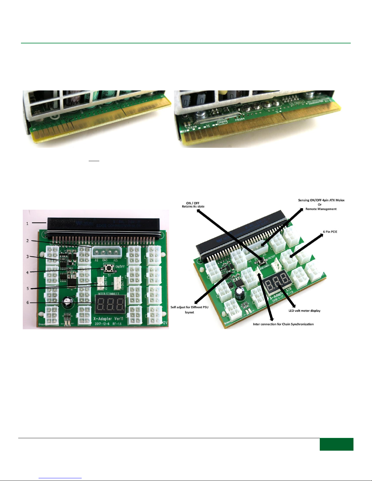
Although the X6B, X7B, and X11 breakout boards were designed to be compatible with the Delta/Dell/Lite-On 1100W and 1400W
server power supplies (picture on the left with 8 smaller pins), they are also backwards compatible with HP 750W, 1200W, 1500W,
and Delta 2400W power supplies (picture on the right with 6 smaller pins). These boards will automatically detect which model power
supply it is currently connected to and adjust itself for compatibility.
The X12 breakout board is only compatible with Delta/Dell/Lite-On power supplies with an 8 pin power bar slot (above picture on the
left).
Breakout Board Features
1: Connector slot. When connecting the breakout board to your PSU we recommend sliding in one corner of the slot from
the PSU and then sliding the rest of the power bar into the connector slot. (Lubricant is not required, but recommended.
Apply on the PSU power bar and wipe away any excess prior to connecting the adapter.)
2: 4 pin Molex input. This is for syncing on/off standard ATX PSU with our server PSU. A second feature of the molex
input is to allow remote access to power on/off your power supplies via our remote management module (coming soon!).
3: Smart chip. Automatically detects and configures itself for compatibility with different power bar designs for server
PSUs.
4: Electronic power button. Even though this is an electronic power button, the board retains its state in the event of a

Parallel Miner’s X6B to X12 Breakout Board Manual |Revised May 2018
2
power loss.
5: Two 4-pin 5v inputs ports. The 4-pin ports will allow you to sync one of our breakout board adapters to another of our
breakout board using our 4-pin cable. DO NOT CONNECT ANY OTHER CABLE TO THIS PORT AS IT WILL
DAMAGE THE BREAKOUT BOARD.
6: LED voltage display. This will provide you with the current voltage output of the power supply.
Interconnect Sync Instructions
Every order containing 2 or more breakout boards will include a free interconnect sync cable to chain each breakout board together.
The cable is approximately 19 inches long.
These breakout boards have two 4-pin input ports; you can sync any amount of power supplies together by connecting the 4-pin port
to the next breakout board’s 4-pin port and so on. We have tested up to 20 linked PSUs.
By syncing the power supplies, you will be able to power on/off all power supplies in the chain by pressing the power button on any
one of the breakout boards in the chain. In the event that one power supply gives out and is no longer working, the sync will not be
interrupted; all working power supplies will still power on/off together.
Dual Fault Protection Instructions
Dual fault protection is the ability to link two power supplies together in
such a way that if one power supply fails, then the second will
automatically shut off. This mode renders the on/off power button
inoperative; turn the PSUs on and off by inserting or removing the power
cord. The dual fault protection cables cannot be used together with the
interconnect sync cable.
Connect the molex of one cable to the first PSU, then connect the 4pin end
of the same cable to the second PSU, connect the molex of the second
cable to the second PSU, and then connect the 4pin to the first PSU.
Watch all features in action here:
https://www.youtube.com/embed/KYPKXVuHFWc
 Loading...