

Parallella P1600, P1601, P1602 Reference Manual

Reference Manual
Parallella-1.x
REV 14.09.09 1

Revision History
Version Comments
0.13.2.13 Initial release
1.13.6.24 Updated PEC_POWER Pin outs
Part Numbers Added + Document Links
Changed flash to 128Mb
Replaced 5V DC/USB power mux with pin header
Changed power sub-system
Epiphany now uses 1.8V IO voltage
Added UART 2-pin header
Changed license to creative common
1.13.7.27 Added UART interface back to PEC_POWER
Added test points for SYS_5V and 1P0V
Added 2-pin header for 5V mounting hole
14.04.15 Removed second USB port “PC connection” as supported feature
No longer supporting the USB-OTG (only host mode)
14.09.09 Removed reference to reset button
nd
Remove reference to 2
USB port
Added numerous tables, design details
REV 14.09.09 2

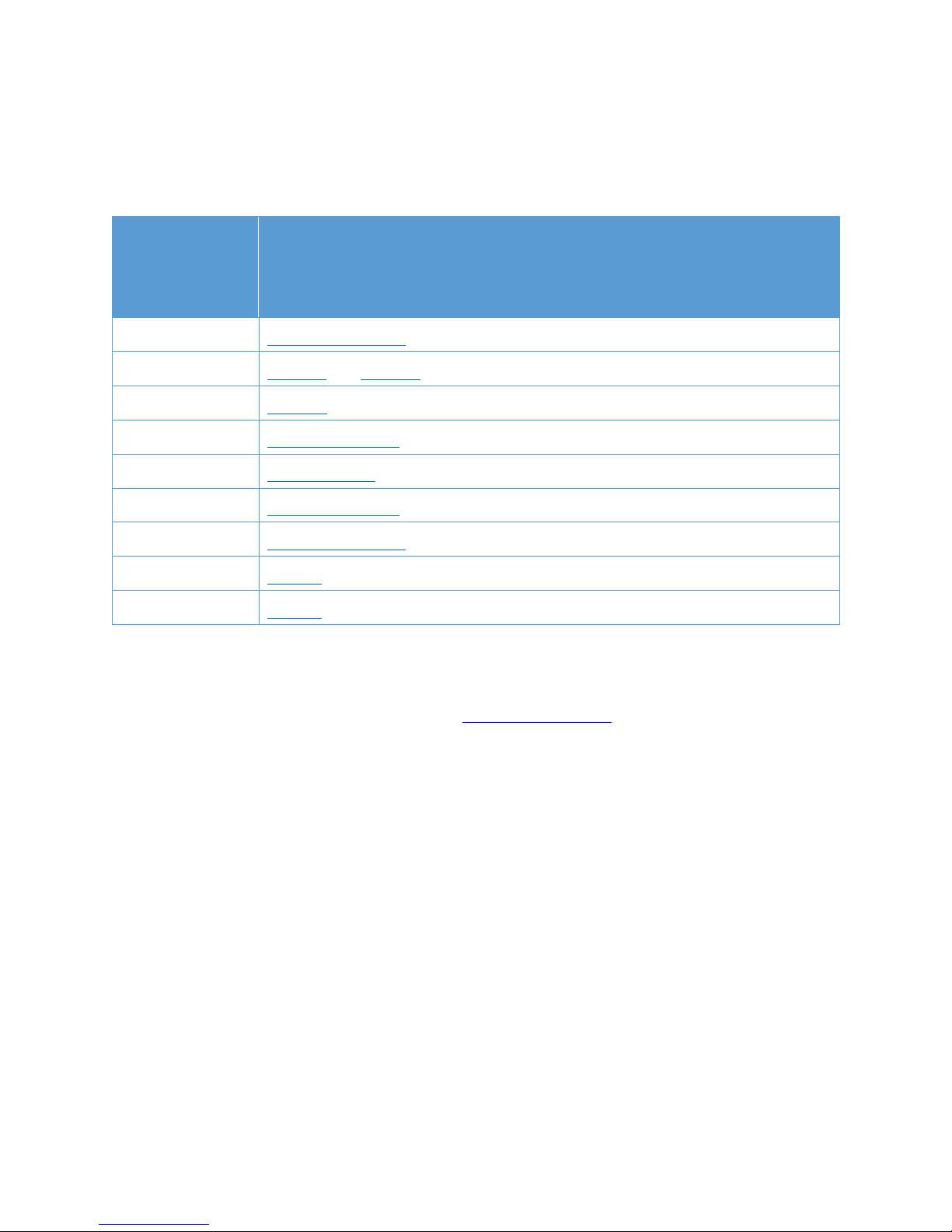
Related Documents
Epiphany Architecture Reference Manual:
http://www.adapteva.com/docs/epiphany_arch_ref.pdf
Epiphany SDK Reference Manual:
http://www.adapteva.com/docs/epiphany_sdk_ref.pdf
Epiphany-III Datasheet:
http://www.adapteva.com/docs/e16g301_datasheet.pdf
Epiphany-IV Datasheet:
http://www.adapteva.com/docs/e64g401_datasheet.pdf
Software Repositories:
Parallella Hardware and Software Repository
https://github.com/parallella
Epiphany SDK Software Repository
https://github.com/adapteva
SD Card Images:
ftp://ftp.parallella.org
REV 14.09.09 3

Contents
Table of Contents
1 Overview ..................................................................................................................................... 9
Table 1: Parallella Feature Summary ............................................................................................................ 9
Figure 1: The Parallella Board (top view) .................................................................................................... 10
Figure 2: The Parallella Board (bottom view) ............................................................................................. 10
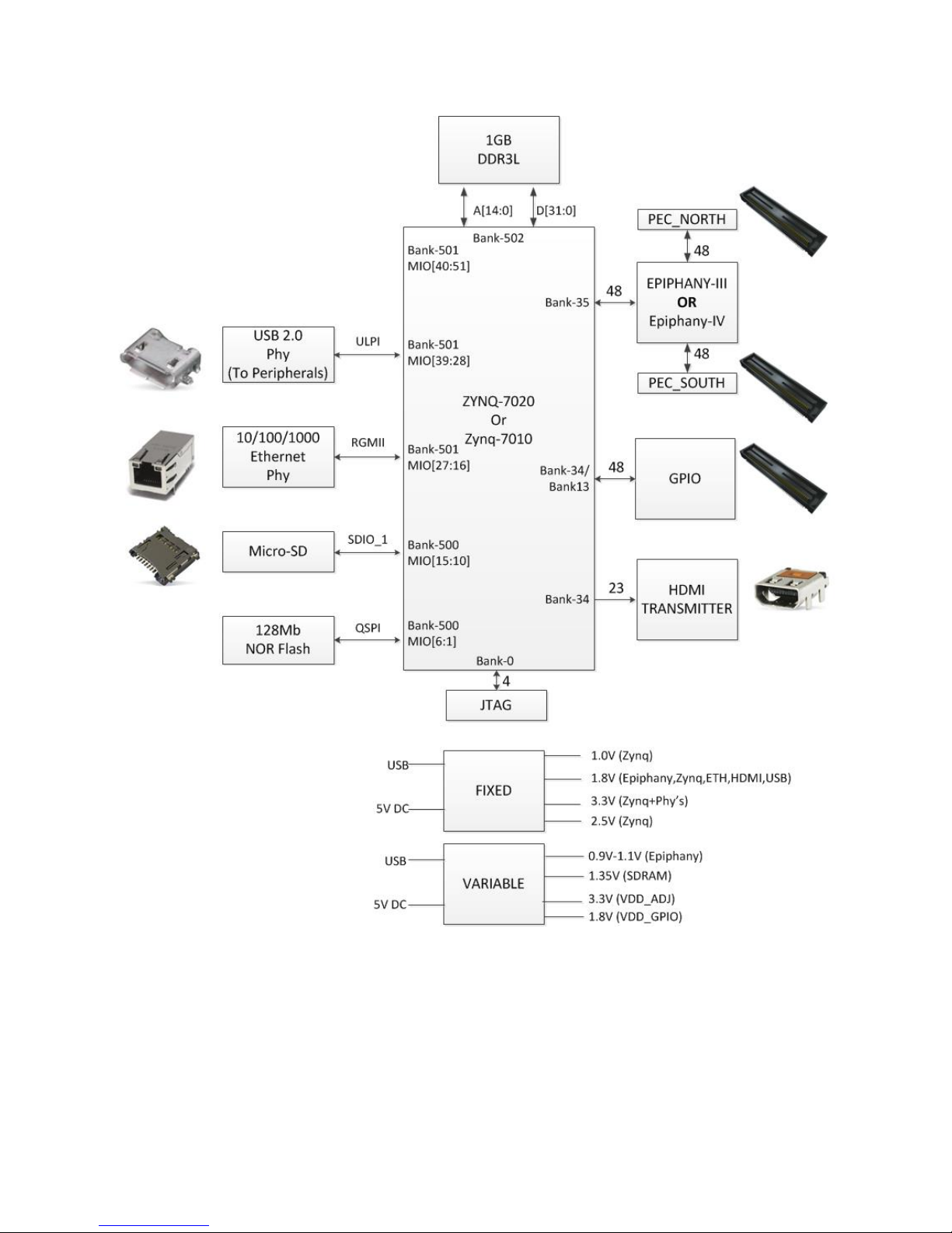
Figure 3: Zynq Connectivity Diagram .......................................................................................................... 11
Figure 4: Parallella High Level Architecture ................................................................................................ 12
2 Quick Start Guide ...................................................................................................................... 13
Step1: Ensure that you have the required accessories ......................................................................... 13
Step 2: Create a bootable micro-SD card .............................................................................................. 13
Step 3: Familiarize yourself with known issues .................................................................................... 13
Step 4. Connect peripherals, fit the heat-sink and apply power .......................................................... 14
Step 5: Build and run a program ............................................................................................................ 14
3 Feature Descriptions ................................................................................................................. 15
3.1 Introduction ................................................................................................................................ 15
3.2 CPU .............................................................................................................................................. 15
3.3 Epiphany Coprocessor................................................................................................................. 17
3.4 SDRAM ........................................................................................................................................ 17
3.5 Flash ............................................................................................................................................ 17
3.6 Gigabit Ethernet .......................................................................................................................... 18
3.7 USB 2.0 Host Port ........................................................................................................................ 18
3.8 Micro SD ...................................................................................................................................... 18
3.9 HDMI Port ................................................................................................................................... 18
3.10 LED Indicators ............................................................................................................................. 18
3.11 Serial Port .................................................................................................................................... 18
3.12 I2C ............................................................................................................................................... 18
3.13 Audio ........................................................................................................................................... 18
3.14 Analog Input ................................................................................................................................ 18
REV 14.09.09 4

3.15 JTAG Debugging .......................................................................................................................... 18
3.16 Powering the board .................................................................................................................... 18
3.17 Parallella On-Board Power Management ................................................................................... 19
3.18 Parallella Supply Outputs ............................................................................................................ 20
3.19 Parallella Expansion Connectors ................................................................................................. 20
3.20 Mounting Holes ........................................................................................................................... 22
4 Parallella System Architecture .................................................................................................. 23
4.1 Zynq Memory Map...................................................................................................................... 23
4.2 Epiphany Memory Map .............................................................................................................. 24
4.3 Epiphany Specific FPGA Resources ............................................................................................. 25
5 Board Configuration ................................................................................................................. 27
5.1 FPGA Pin Assignment .................................................................................................................. 27
6 Booting the Parallella ................................................................................................................ 32
7 Parallella Expansion Connector Details .................................................................................... 33
7.1 PEC_POWER ................................................................................................................................ 33
7.2 PEC_FPGA .................................................................................................................................... 36
7.3 PEC_NORTH/PEC_SOUTH ........................................................................................................... 38
8 Electrical and Performance Specifications ............................................................................... 43
8.1 Dimensions and Weight .............................................................................................................. 43
8.2 Power Consumption ................................................................................................................... 43
8.3 Performance Metrics .................................................................................................................. 43
8.4 IC Metrics Summary .................................................................................................................... 44
9 About the Parallella Board ........................................................................................................ 45
9.1 Design Information ..................................................................................................................... 45
9.2 Build Options ............................................................................................................................... 45
9.3 Contributors ................................................................................................................................ 46
9.4 Attributions ................................................................................................................................. 47
9.5 Licensing ...................................................................................................................................... 47
9.6 Disclaimers .................................................................................................................................. 48
9.7 Warranty ..................................................................................................................................... 50
REV 14.09.09 5

REV 14.09.09 6

List of Figures
Figure 1: The Parallella Board (top view) .................................................................................................... 10
Figure 2: The Parallella Board (bottom view) ............................................................................................. 10
Figure 3: Zynq Connectivity Diagram .......................................................................................................... 11
Figure 4: Parallella High Level Architecture ................................................................................................ 12
Figure 5: Power Management .................................................................................................................... 19
Figure 6: PEC Placement Diagram ............................................................................................................... 21
Figure 7: Parallella Expansion Connectors (PEC) ........................................................................................ 21
Figure 8: Daughter Card Configurations ..................................................................................................... 22
Figure 9: Zynq Memory Map....................................................................................................................... 23
Figure 10: Epiphany Memory Map ............................................................................................................. 24
List of Table
Table 1: Parallella Feature Summary ............................................................................................................ 9
Table 2: Parallella IC summary .................................................................................................................... 15
Table 3: Zynq Feature Summary ................................................................................................................. 16
Table 4: Epiphany System Registers ........................................................................................................... 26
Table 5: Zynq Bank32 Pin Assignments ....................................................................................................... 28
Table 6: Zynq Bank 34 Pin Assignments ...................................................................................................... 30
Table 7: Zynq Bank 13 Pin Assignments ...................................................................................................... 31
Table 8: PEC_POWER Signal Summary ....................................................................................................... 34
Table 9: PEC_POWER Pin Mapping ............................................................................................................. 35
Table 10: PEC_FPGA Signal Summary ......................................................................................................... 36
Table 11: PEC_FPGA Pin Mapping ............................................................................................................... 37
Table 12: PEC_NORTH/SOUTH Signal Summary ......................................................................................... 38
Table 13: PEC_NORTH Pin Mapping for Parallella-16 ................................................................................. 39
Table 14: PEC_NORTH Pin Mapping for Parallella-64 ................................................................................. 40
Table 16: PEC_SOUTH Pin Mapping for Parallella-16 ................................................................................. 41
Table 17: PEC_SOUTH Pin Mapping for Parallella-64 .................................................................................
REV 14.09.09 7
42

Table 18: Dimensions and Weight .............................................................................................................. 43
Table 19: Power Consumption .................................................................................................................... 43
Table 20: Paralllella Performance Summary ............................................................................................... 44
Table 21: IC Metrics .................................................................................................................................... 44
REV 14.09.09 8

1 Overview
The Parallella board is a high performance computing platform based on a dual-core ARM-A9 Zynq
System-On-Chip and Adapteva’s Epiphany multicore coprocessor. Current commercially available models:
Model
P1600 P1601 P1602
Mnemonic “Microserver” “Desktop” “Embedded”
Host
Processor
Xilinx Zynq Dual-core ARM A9
XC7Z010
Xilinx Zynq Dual-core ARM A9
XC7Z020
Epiphany 16-core CPU
Coprocessor
E16G301
Memory 1 GB DDR3
Ethernet Gigabit Ethernet
Boot Flash 128Mb QSPI Flash
Power 5V DC
Storage Micro-SD
USB No USB 2.0 Host Port
HDMI No Micro HDMI
GPIO Pins 0 24 48
eLink
Connectors
0 2 2
FPGA
Logic
28K Logic Cells
80 DSP Slices
28K Logic Cells
80 DSP Slices
80K Logic Cells
220 DSP slices
Weight 1.3 oz (36 grams) 1.4 oz (38 grams)
Size 3.5″ x 2.1″ x 0.625″ (90mmx55mmx18mm)
SKU P1600-DKxx P1601-DKxx P1602-DKxx
HTS Code
(Schedule B)
8471.41.0150 8471.41.0150 8471.41.0150
Table 1: Parallella Feature Summary
REV 14.09.09 9
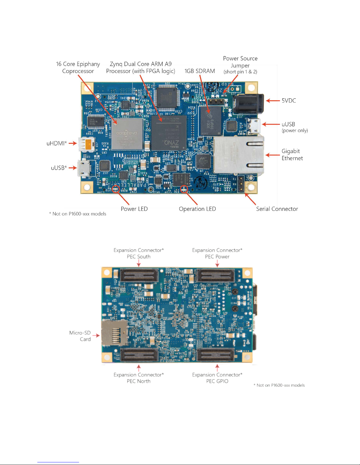
Figure 1: The Parallella Board (top view)
REV 14.09.09 10
Figure 2: The Parallella Board (bottom view)
REV 14.09.09 11
Figure 3: Zynq Connectivity Diagram

Figure 4: Parallella High Level Architecture
REV 14.09.09 12
2 Quick Start Guide
This section is a summary of the quick start guide is found at www.parallella.org/quick-start
Step1: Ensure that you have the required accessories
• A high quality 2000mA rated 5V DC power supply with 5.5mm OD / 2.1mm ID center positive
polarity plug.
• An ethernet cable
• A fan (required for boards sold before July 10th, 2014, recommended for all others)
• A micro HDMI to HDMI cable (not needed for headless option)
• A USB male Micro-B to female Standard-A cable (not needed for headless option)
Step 2: Create a bootable micro-SD card
Burn a fresh Micro-SD card using the latest distribution.
• Instructions for creating an SD card
Note: Burn a fresh SD card even if you were shipped a pre-programmed micro-SD card!
Step 3: Familiarize yourself with known issues
• The board does get hot so you have to take precautions to cool the board properly. Before
letting the board run for hours, you must ensure that the board doesn’t overheat. (preferably by
using the ‘xtemp’ utility
• Boards used without a fan must be placed vertically.
• The Parallella is sensitive to static discharge and must be handled appropriately.
• If you were shipped a board before March 1st, 2014, then you must use a conforming powered
.)
USB hub.
• If you were shipped a board before July 10th, 2014 then you must use a fan with the board. (we
do still recommend a fan for all customers, especially if you are going to push the performance
of the board)
REV 14.09.09 13

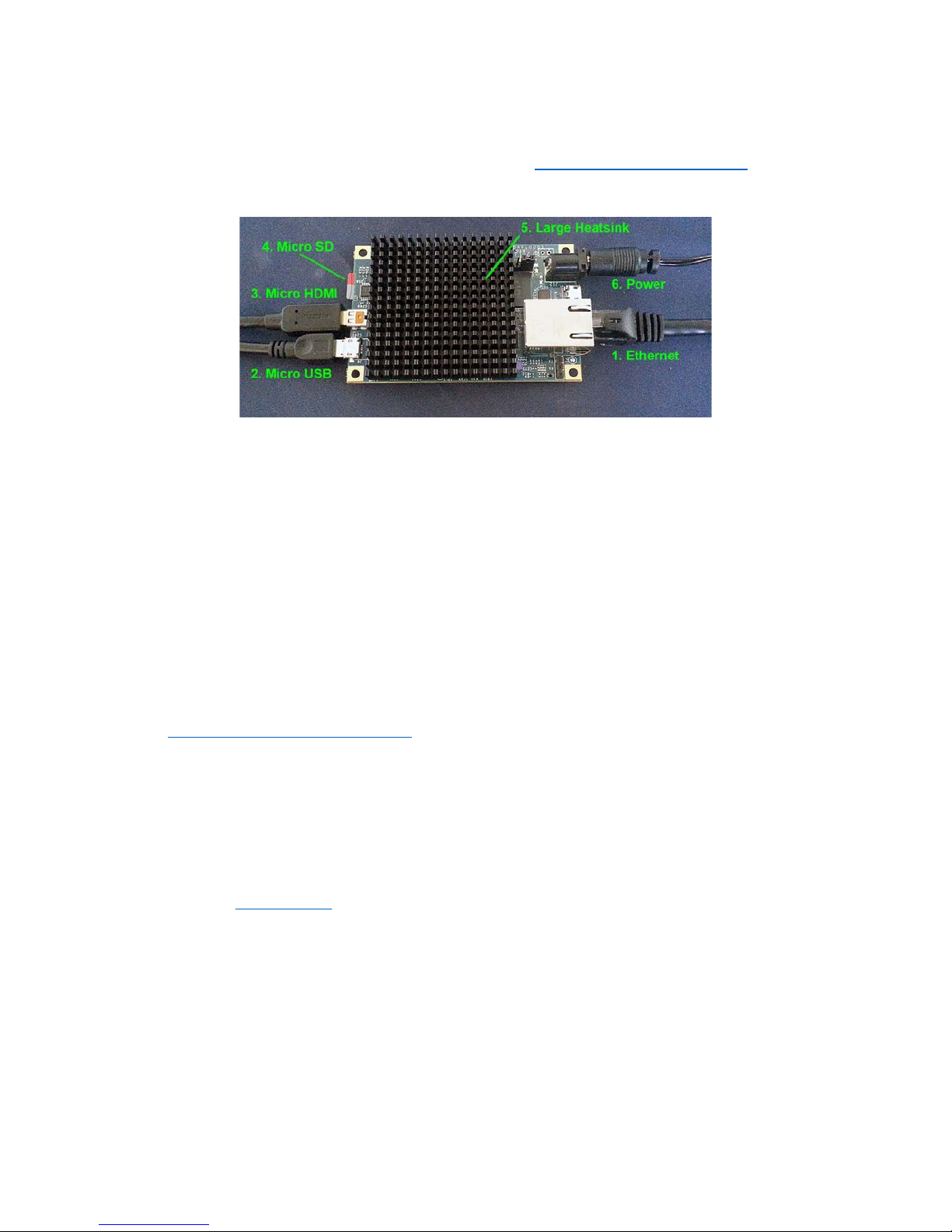
Step 4. Connect peripherals, fit the heat-sink and apply power
• Connect the cables as indicated by #1-4 in the picture above
• Attach a heatsink to the Zynq device (#5 in right hand picture) OR install the new large heatsink
onto the Parallella board
• Make sure a fan is directed at the board if required. A fan is required when using the small
heatsink (right hand picture above). With the large heatsink (left hand picture above) the board
will function in normal conditions without requiring a fan, depending on your usage. Monitor
the temperature using a utility such as xtemp, and keep the chip temp below 70 degrees Celsius.
• Apply power (#6 in picture)
Step 5: Build and run a program
The system will boot and a login screen will appear.
Login with the username linaro and password linaro.
REV 14.09.09 14
3 Feature Descriptions
3.1 Introduction
The Parallella-1.x board uses the components listed in the table below.
Device
Part Number (and datasheet link)
CPU Zynq™-7000 AP SoC
Epiphany E16G301 and E64G401
Eth PHY 88E1318
USB PHY
HDMI PHY
SDRAM
Flash
USB3320C-EZK-TR
ADV7513BSWZ
MT41K256M32SLD
N25Q128A13EF840E
PMIC #1 ISL9307
PMIC #2
ISL9305
Table 2: Parallella IC summary
3.2 CPU
The central processor on the Parallella board is the
Zynq™-7000 AP SoC. The Zynq represents a new class
of processor product which combines an industry-standard ARM® dual-core Cortex™-A9 MPCore™
processing system with Xilinx 28nm programmable logic. The Zynq SoC includes the following set of
features:
Dual-core ARM® Cortex™-A9 CPU:
• Coherent multiprocessor support
• ARMv7-A architecture
• 32 KB Level 1 4-way set-associative instruction/data caches (independent for each CPU)
• 512 KB 8-way set-associative Level 2 cache shared between CPUs
• TrustZone® security
• Jazelle® RCT execution Environment Architecture
• NEON™ media-processing engine
• Single and double precision Vector Floating Point Unit (VFPU)
• CoreSight™ and Program Trace Macrocell (PTM)
• Three watchdog timers, one global timer, two triple-timer counters
REV 14.09.09 15
 Loading...