

Parallax Power Supply ATS 501 Series Manual

SPECIFICATIONS
Electrical rating: 120/240 volts AC 60 HZ @ 50amperes.
ETL listed for US and Canadian applications.
Maximum generator: 12KW
Enclosure: UL Type 1, 16 GA Steel.
Dimensions:
Model Height Width Depth Weight
ATS 501
Not ignition protected.
SPECIFICATIONS SUBJECT TO CHANGE WITHOUT PRIOR NOTICE.
3.75 in. 8.70 in. 11.05 in. 6.0 lbs.
100 West 11th Street, Suite 100
ANDERSON, IN 46016
www.parallaxpower.com
MODEL ATS 501
AUTOMATIC
LINE / GENERATOR
SWITCH
FOR RECREATIONAL VEHICLE USE ONLY!
NOT FOR LIFE SUPPORT!
Series
Wiring Instructions
The ATS should be installed by a qualified electrician.
CAUTION:
Observe the polarity and torque specifications per the installation label
included on the inside cover of each unit.
WARRANTY STATEMENT
Parallax warrants each ATS to be free from defects in materials and workmanship
under normal use and service and limits the remedies to repair or replacement. This
warranty extends for two years from the date of purchase and only valid to the
original owner and within the continental limits of the United States and Canada. If a
problem should occur within the first 24 months of purchase, please contact a dealer
that handles warranty on your brand of boat or RV.
No user serviceable parts inside. This warranty does not cover damage due to
improper installation, abuse or accidents.
ATS 501
PN # 011-5171-001 REV B
INTRODUCTION
Thank you for purchasing the Parallax Model ATS501 automatic RV Line/ Generator
switch. We are confident that the ATS 501 will give you outstanding performance for
many years. If you have any questions or comments about this product, please contact
Parallax’s customer service representative at the address or phone and fax numbers
listed below.
Parallax Power Supply
100 West 11
Phone: 1-800-443-4859
Fax. : 1-765-608-5235
GENERAL INFORMATION
The ATS 501 is designed to automatically switch the on board 120 or 240 volt
appliances to generator power when the generator is activated.
No longer do you need to go outside, remove the shoreline cord from the pole and
plug it into the generator receptacle. Likewise in marine applications you simply
start the generator and the ATS501 will switch the loads for you.
OPERATION
After the ATS 501 is installed using one of the typical installations shown in this
manual, it will be ready for years of trouble free service. Operation is automatic and
is maintenance free.
FROM SHORELINE:
To operate appliances from shoreline power, simply plug in the shoreline cord to the
power pole at the campground or dock. The ATS 501 automatically connects all AC
Appliances to shoreline power.
FROM GENERATOR:
To operate appliances from on board generator simply start the generator.
After a typical 20 second delay to allow the generator to stabilize the ATS 501 will
engage, transferring all 120 or 240-volt appliances connected to the ATS 501 load
terminals to the generator.
AUXILIARY CONTACT OPERATION
The ATS 501 RV line generator switch when connected as in the typical installation
II shown in this manual may control other equipment in your vehicle. The auxiliary
contacts are rated for 30 A @ 120 VAC operation and will switch other loads as the
ATS 501 switches from shore power to generator. These contacts are supplied as
non-energized dry contacts.
th
Street, Suite 100 Anderson, IN 46016
MOUNTING LOCATION
The ATS 501 series may be installed in any position, leaving room for routing
shoreline, generator and load conductors. To minimize voltage drop in the wiring the
transfer switch should be located as close to the generator and shoreline cord entrance
as practical.
DO NOT
install the ATS 501 series in the generator compartment.
The ATS 501 series is not ignition protected and should not be mounted in the same
compartment as batteries or flammable materials such as gasoline. It may be mounted
in the cabin or living area or a basement compartment, but is not suitable for outside
locations.
The ATS 501 should be installed by a qualified electrician.
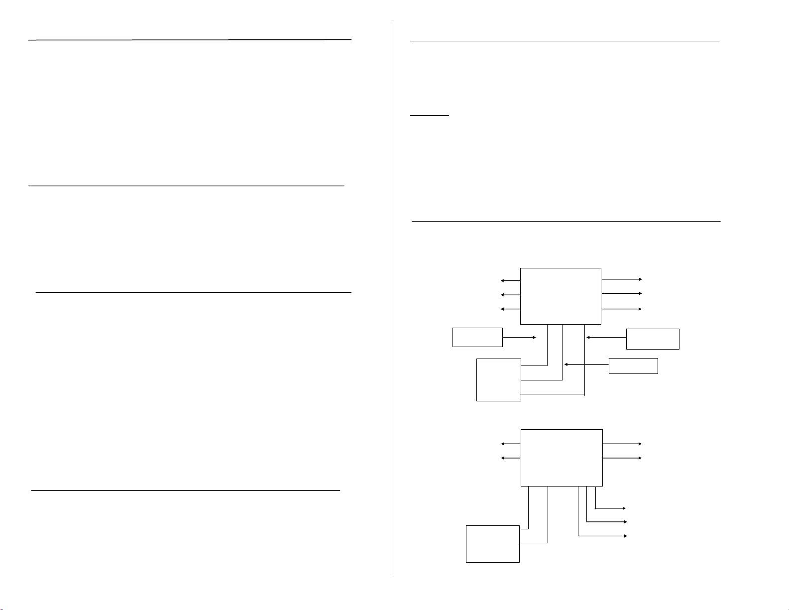
Typical Installations
Typical Installations
Rated - 50A 120/240 Volts 60Hz, Neutral rated 70A with jumpers installed.
INSTALLATION I
L1
120 / 240
50 A - SHORE
LINE POWER
NEUT.
L2 L2
ATS 501
With jumpe rs installed.
L1
NEUT.
LOAD
** Circuit 1
120 VAC - 35 A Max.
2 CIRCUIT
GENERATOR
120 VAC
** Circuit 2
120 VAC - 35 A Max.
Neutral rated
70 A Max.
** Note: Circuit1 and Circuit 2 in phase.
INSTALLATION II
120 VAC
30 A - SHORE NEUT. LOAD
LINE POWER
L1
ATS 501
NC CON T ACTS.
NO 120 VAC
DRY A UX.
RATED 30A
120 VAC
30 A - Ma x .
GENERATOR
L1 C
NEUTRAL
 Loading...