

Page 1
Web Site: www.parallax.com
Forums: forums.parallax.com
Sales: sales@paral la x.c om
Technical: support@parallax.com
Office: (916) 624-8333
Fax: (916) 624-8003
Sales: (888) 512-1024
Tech Support: (888) 997-8267
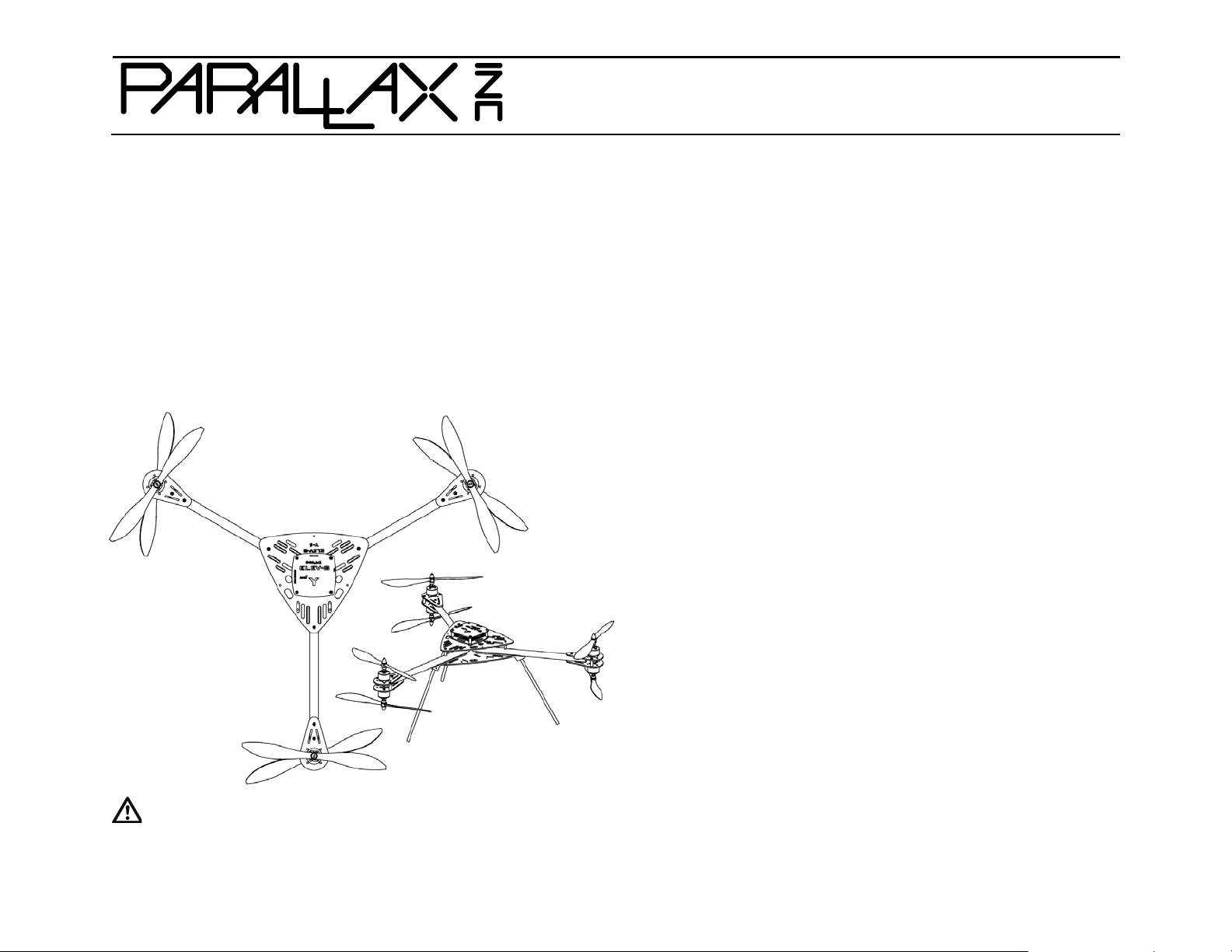
ELEV-8 Y-6 Multicopter Kit (#80100) Information and Assembly Guide
Features
Six-rotor system with fixed-pitch blades
Propeller P8X32A microcontroller flight control board
Pre-programmed with flight-control software
Custom plates protect motors and electronics
Designed to easily attach a camera mount
Great for FPV (First-Person-View) Camera Systems
Specifications
Weight, without battery: 2.7 lbs (1.23 kg) fully assembled
Payload capacity, excluding battery: ~ 4 lbs (1.8 kg)
Average assembly time: 8 hours
Height (assembled): 9 in (23 cm)
Rotor-to-rotor width (centers): 22 in (55.9 cm)
Additional Items Required
RC radio controller and receiver, 5-channel mini mum for flight
2 LiPo Batteries, 3000 to 4400 mAh 3-cell 30 C discharge rate
LiPo Battery Charger
PC running Windows to configure the control board firmw are for
Y6 operation
Application Ideas
Hobby RC flying
Aerial photography
Flying tele-presence platform
CAUTION: READ ALL WARNINGS AND PREC AUTIONS (PAGE 2) BEFORE ASSEMBLY OR OPERATION!
Copyright © Parallax Inc. ELEV-8 Y-6 Multicopter Kit (#80100) Version 1.0 Page 1 of 31
Page 2

READ THIS FIRST – IMPORTANT SAFETY INFORMATION!
behind
READ ALL WARNINGS AND PRECAUTIONS ON THIS PAGE BEFORE
ASSEMBLY OR O PERATION!
WARNING: CUTTING HAZARD. Rotating ELEV-8 Y-6 blades can cut skin and
underlying tissues. Stay away from a powered ELEV-8 Y-6 Multicopter and
never become complacent during operation.
WARNING: ENTANGLEMENT HAZARD. Secure long hair and loose clothing
or jewelry when building, testing, and operating your ELEV-8 Y-6
Multicopter to avoid entanglem ent with motors.
WARNING: EYE HAZARD. Always wear eye protection when assembling,
soldering, operating, or repairing y our ELEV-8 Y-6 Multicopter.
Customer agrees to fly at Academy of Model Aeronautics (AMA) approved
flying field s , maintaining insurance through their AMA membership.
Inform yourse lf of and follow al l current federal, state, and local laws
regarding the use of hobby RC ai rc raft in the area where you plan to
operate your ELEV-8 Multicopter craft. Review the FAA’s rules in entirety –
you are responsi ble for following them.
An ELEV-8 Y-6 Multicopter assembled and used as directed in this document
is an RC hobby aircraft and does not constitute the use of an autonomous
UAV or drone. Modifying your ELEV-8 Y-6 Multicopter to function as an
autonomous UAV or drone is not su pported, recommended, or endorsed by
Parallax Inc . If you choose to m odify your ELEV-8 Y-6 Multicopter to
function as an autonomous UAV or drone, you do so e n tirely at your own
responsibility and risk.
This kit is not for beginners. Advanced mechanica l skill is required for
building and flying an ELEV-8 Y-6 Multicopter. RC aircraft experience is
highly recommended.
DISCLAIMER OF LIABILITY: PARALLAX INC. IS NOT RESPONSIBLE FOR ANY SPECIAL, INCIDENTAL, OR CONSEQUENTIAL
DAM AGE S AND P ER SO NAL INJURIES, INCLUDING THAT TO LIFE AND HEALTH, RESULTING FROM THE CUSTOMER’S APPLICATION
AND U SE OF ANY PAR ALLAX INC. PRODUCTS. YOU, T HE CUSTOMER, ASSUME FULL AND UNLIMITED RESPON SIBILITY FOR ALL
CUSTOMER ELEV-8 Y-6 MULTICOPTER APPLICATIONS AND USES.
Follow the instructions careful ly; incorrect assembly of your EL EV-8 Y-6
Multicopter could cause risk of catastrophic equipment failure, personal
injury to you or others, and property damage.
Perform initial electronic speed controller (ESC) programming before
installing the propeller blades. Remove propeller blades before
reprogramming th e ESCs .
Establish and test the radio link between the RC controller and RC receiver
before installing the propeller blades. Remove propeller blades before
testing a different controller.
Always disconnect the battery when not in use.
Store your ELEV -8 Y-6 Multicopter and its radio controller out of reach of
children, pets, and those who do not know how to us e them safely.
Only operate your ELEV-8 Y-6 Multicopter in an area with no children,
unsecured pets, or livestock, which can be harme d by contact with rotating
blades. For example, children and dogs may try to jump and catch a flying
Y-6 Multicopter, or may run to inve s tigate one that has just landed.
Only operate your ELEV-8 Y-6 Multicopter outdoors and away from crowded
areas. All observers should stand a safe di stance
the operator.
Only operate your ELEV-8 Y-6 Multicopter in an environment where you can
maintain unobstructed visual contact with it. Do not operate at night, or
where there is fog, smoke, or dust that could limit visibility.
Keep your ELEV-8 Y-6 Multicopter dry! Do not submerge your ELEV-8 Y-6
Multicopter or operate it in rai ny or damp conditions. Beware of sprinklers
and of landing in wet vegetation.
Check the wind speed before flying your ELEV-8 Y-6 Multicopter. Even a
light breeze can make flying difficult for beginners. No one should fly in high
winds.
Copyright © Parallax Inc. ELEV-8 Y-6 Multicopter Kit (#80100) Version 1.0 Page 2 of 31
Page 3
Bill of Mater ials
ELEV-8 Y-6 Kit Contents (#80100)
31500
1
Hoverfly OPEN Board
700-10003
1
Safety glasses
80120
1
ELEV-8 Y-6 Hardware Kit
713-00019
4
Spacer, #4,x1/8", NY
750-90000
6
HW30A ESC
710-00042
4
Scre w, 4-40, 1 1/4", PH, SS
750-00059
1.25
12 AWG silicone wire, stranded, red
730-00060
3
ELEV-8 Boom (Black)
710-00039
24
Scre w, 3 x 6 mm, 0.5 thread, black
350-00044
1.5
Red LED Tape
This bill of materials is pro vided so you may i nventory each bag in y our ELEV-8 Y-6 Multicopter Kit before be ginning construction. I f you are
missing any parts, contact sales@parallax.com
listed separately. Parts and quantities subject to change without notice. Some items are available online from www.parallax.com.
Part # Qty Description
80130 1 ELEV-8 Y-6 Airframe Kit
directly for assistance. Note that some items are small sub-kits with additional components not
ELEV-8 Y-6 Hardware Kit (#80120)
Part # Qty Description Part # Qty Description
712-00007 4 Washer, #6, 3/8" OD, Zinc 750-90002 6 Brushless 1000kV
700-00085 3 Screw, #6-32x1/8", Set, SS 721-80001 3 GemFan 10x4.5-C Regular Carbon
700-00036 4 Nut, #4-40, Nylon 721-80000 3 GemFan 10x4.5-C Pusher Carbon
ELEV-8 Y-6 Electronics Kit (#80110)
80110 1 ELEV-8 Y-6 Electronics Kit
85000 1 ESC Programming Card
ELEV-8 Y-6 Airframe Kit Contents (#80130) 710-00006 8 Screw,#4-40x1/2",PH,SS 800-00021 2 16" Red Pluggable Jumper-Male
Part # Qty Description 700-00024 4 Locknut, 4-40, 1/4" 800-00022 2 16" Black Pluggable Jumper-Male
721-80010 1 ELEV-8 Control Board Top Plate 710-00100 6 Scre w, 4-40, 1/4", PH, Black 350-00045 3 White LED Tape
721-80002 1 Control Board Mounting Plate 720-28001 1 Light Pipe 452-00088 1 Nylon housing EC3 Plug 10-pack
721-80012 1 Y-6 Chassis Plate Top 725-00067 1 1.5 mm Hex Key 450-00050 2 3.5mm Gold Bullet Conn 10-Pk
721-80013 1 Y-6 Chassis Plate Bottom 700-00106 1 Loctite 242 800-00036 13.5 Heat-shrink 3/4" dia. tubing, clear
721-80006 6 ELEV-8 Motor Mount Bottom 900-00021 2 Nylon Strap, Black 800-00023 36 Heat-shrink 3/16" dia. tubing, black
730-00062 3 Y-6 Landing Gear Mounts 700-00059 24 Washer, Lock, #4, Internal Zinc 800-00039 3 Heat-shrink 1/2" dia. tubing, black
721-80014 3 Y-6 Landing Gear(carbon fiber rods) 700-00093 12 Zip Tie, 4", Black 800-00080 5 3-wire extension, 22AWG, F/F, 8"
120-00006 0.5 5" Red/White Checkered Sticker
120-00007 1 5" Black/White Checkered Sticker
713-00043 16 Standoff, nylon, 4-40, 5/8" threaded 750-00056 21 16 AWG silicone wire, stranded, red
710-00036 12 Screw, 4 -40, 3/8", PH, SS 750-00058 1.25 12 AWG silicone wire, stranded, blk
Copyright © Parallax Inc. ELEV-8 Y-6 Multicopter Kit (#80100) Version 1.0 Page 3 of 31
Page 4

ELEV-8 Y-6 ASSEMBLY INSTRUCTIONS
These instructions are for assembling the ELEV-8 Y-6 in its most sta ndard configuration. Some steps are optional; we’ll explain those along the
way. The ELEV-8 Y-6 Multicopter platform is designed for creative experimentation and adaptation; however, we recommend that you try the
standard configuration first, and then experiment at your own educated risk.
These instructions are available online as a full-color PDF; go to www.parallax.com
and search “80100”.
Preparation
1. Read the entire assembly instructions before beginning.
Assembly and testing takes about eight hours on average.
Tools Required
Soldering iron, solder, and flux
Component vise
2. If you are missing any components, email
support@parallax.com or call 888-512-1024 (inside
continental US) or 916-624-8333.
3. Gather all of the additional items and tools required.
4. Charge your LiPo batteries with their charger.
Additional Items Required
RC radio controller and receiver, 5-channel minimum for flight
2 LiPo Batteries, 3000 to 4400 mAh 3-cell 30 C discharge rate
LiPo Battery Charger
#1 Phillips screwdriver
1/4 inch wrench, box-end or socket
11/32 inch wrench or nut driver
Wire strippers/cutters (12-16 AWG)
Scissors
Needle-nose pliers
Ruler or measuring t ape
Heat gun or blow dryer (for heat-shrink tubing)
PC running Windows to configure the control board firmware for
Y6 operation
Step 1: Motor Set Screws
Start by applying Blue Loctite to the motor set screws, to prevent them from coming loose during flight and causing equipment failure.
1. Locate the Blue Loctite 242, the six motors, and the 1.5 mm Hex Key in the ELEV-8 Hardware Kit.
2. Refer to the drawing on the next page. Using the Hex Key, carefully remove the Motor Set Screws (item 2) from ea ch motor (item 1). The
screws may be very tight; be careful not to break your Hex Key.
3. For each motor, apply a small amount of Blue Loctite to the Set Screw t hreads and caref ully reinstall the s crews. Seat each s crew firmly but
do not over-tighten. Allow the Blue Loctite to set for 10 minutes. It fully cures in 24 hours.
Copyright © Parallax Inc. ELEV-8 Y-6 Multicopter Kit (#80100) Version 1.0 Page 4 of 31
Page 5

Copyright © Parallax Inc. ELEV-8 Y-6 Multicopter Kit (#80100) Version 1.0 Page 5 of 31
Page 6
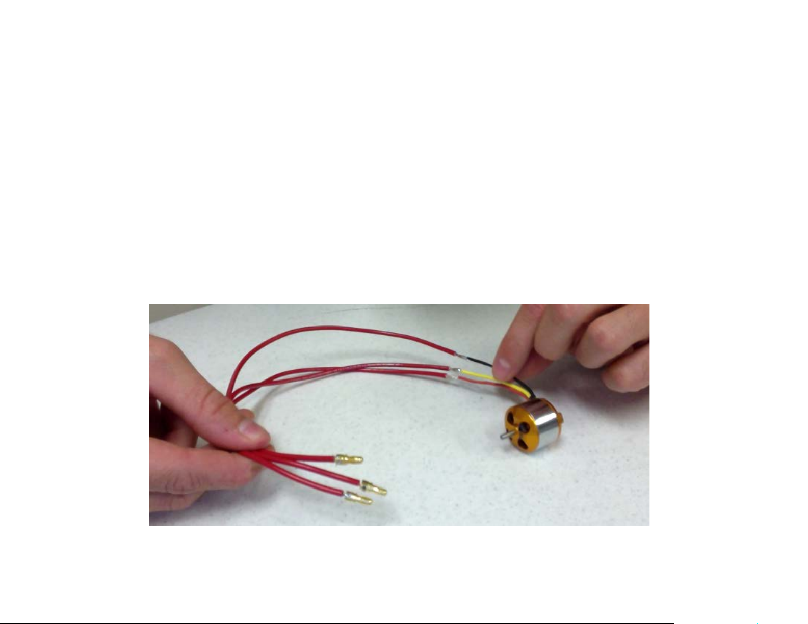
Step 2: Solder the Motor and ESC Speed Controller Connectors
In this step you will solder long leads to the motors. Then, you will solder EC3 connectors to each lead and each Elect ronic Speed Controller
(ESC). The E C3 conne ctor s will give you the ability to switch around the wire connectio ns when you che ck your mo tor dire cti on late r in the bui ld.
Be sure to use all of the same “gender” for the leads, and all of the opposite “gender” for the speed controllers. Follow the instructions below.
1. Gather together your motors, the red 16 AWG wire, EC3 connectors, wire cutters, wire stripper, ruler, and soldering supplies.
2. Using a ruler and wire cutters, measure and cut eighteen lengths of the red 16 AWG wire, each 14 i nches (35.6 cm) long.
3. Use wire strippers to remove the insulation and expose about 1/4 inch (0.6 cm) of metal at one end, and 1/8 inch (0.3 cm) at the other end.
4. Solder a wire (the 1/4-inch exposed end) to each lead on all six motors.
5. For this step, use all male or all female EC3 connectors (we used male EC3s here). To solder an EC 3 connector to the opposi te end of each
lead, insert the 1/8-inch exposed ti p of the wire into the cup end of the bullet connector, and fill the cup with solder.
Copyright © Parallax Inc. ELEV-8 Y-6 Multicopter Kit (#80100) Version 1.0 Page 6 of 31
Page 7
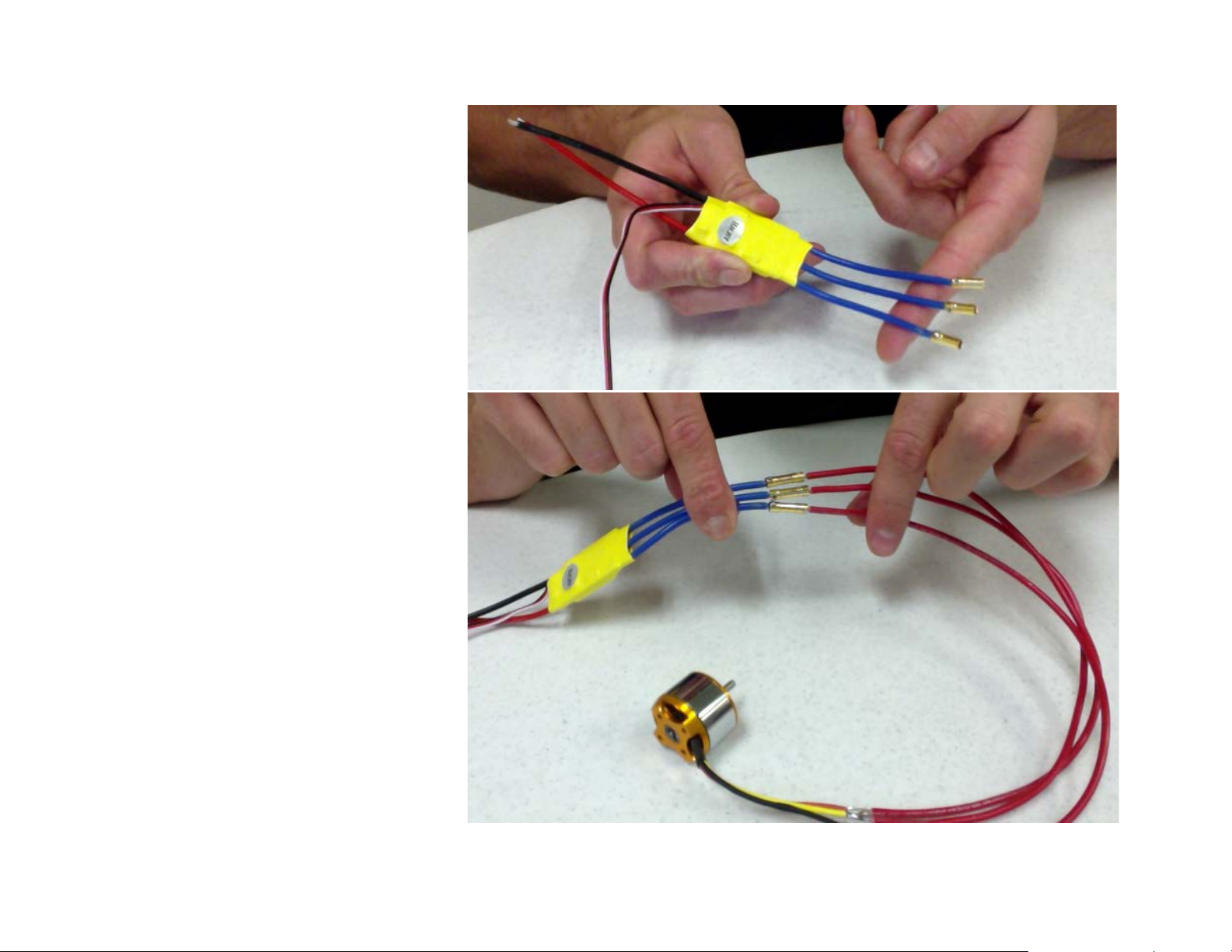
6. If necessary, use wire strippers to expose
1/8 inch (0.3 cm) of metal on the end of
each speed controllers’ blue wire leads.
7. Solder an opposite-gender EC3 connecto r to
the end of each speed controllers’ blue leads.
8. Connect the male EC3 connectors to the
female EC3 connectors of your speed
controller, to verify that they fit properly.
9. Disconnect them again for now.
Copyright © Parallax Inc. ELEV-8 Y-6 Multicopter Kit (#80100) Version 1.0 Page 7 of 31
Page 8

Step 3: Apply Heat-shrink Tubing to Motor and ESC Leads
Heat-shrink tubing will protect the solder joints and pre vent unintended e lectrical conta ct. In the top picture, the tubing is fully shr unk over the
motor-ESC lead solder joints. However, in the bottom picture, the tubing is only p artially shrunk over an ESC lead’s EC3 connector. This keeps the
leads from accidentally making contact wit h each other, yet allows the connect ors to be plugged and unplugged if needed when testing motor
connections in a later step.
1. Locate the length o f 3/16” black tub ing. Measure and
cut eighteen pieces, each 3/4-inch (1.9 cm) long.
2. Slip a piece of tubing over each solder joint on ea ch
motor lead.
3. Apply heat with a hea t gun or blow dr yer t o shr ink the
tubing over the solder joint, as shown (top).
4. Measure and cut eighteen more pieces of heat-shrink
tubing, each 1 inch (2.5 cm) long.
5. Slide a piece of tubing over an ESC lead.
6. Plug in the opposite connector from the motor
assembly. Position the tubing to cover both connectors and solder joints.
7. Disconnect the motor assembly lead but keep the
tubing in place. C arefully apply he at to just the ve ry
end of the tubing where it covers the ESC lead and
connector solder joint. Apply just enough heat to
secure the tube to the wire behind the conne ctor, as
shown in the picture (right). Do not let the other end
of the tubing shrink.
8. Test that you can still plug and unplug the motor lead
connector into the ESC connector.
9. Repeat with the other 11 ESC leads, and then
disconnect the motors from the ESCs for now.
Copyright © Parallax Inc. ELEV-8 Y-6 Multicopter Kit (#80100) Version 1.0 Page 8 of 31
Page 9

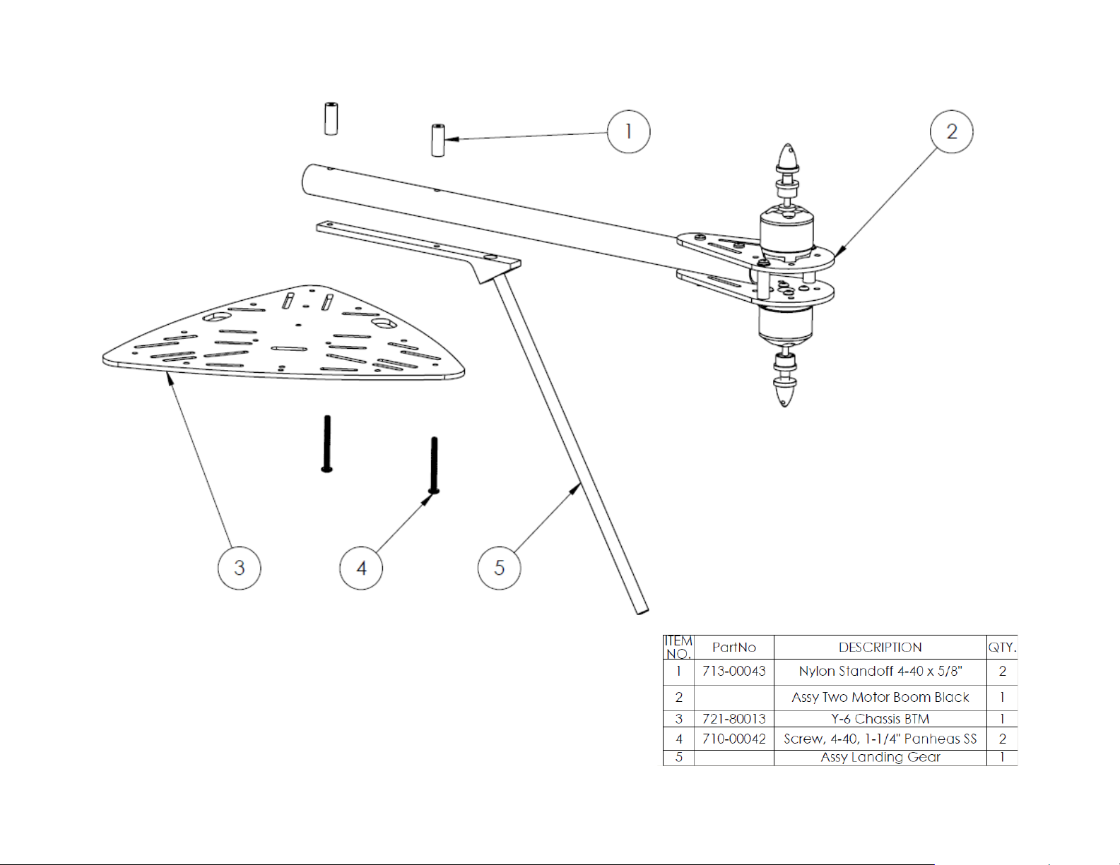
Step 4: Motor Mount Assembly
In this step, you will attach the Motor Mounts and Motors to the Booms. DO NOT ATTACH THE PROPELLERS TO THE MOTORS YET.
1. Gather the items listed in the diagram on the next page.
2. Attach each Motor (item 1) to a Motor Mount Bottom plate (item 4). Use four 3 mm x 6 mm screws (item 9) for each motor.
3. Use two 3/8” Panhead Screws (item 6) a nd two I nternal Toot h Lock Was hers (item 7) to attach two 5/8” Nylon Standoffs (item 8) to one of
the Motor M ount bottom pl ates. Use two more 3/8” Panhead Screws and Internal Tooth L ock Washe rs to a ttach the se cond Motor Assembly
to the Nylon Standoffs (item 8).
4. One end of each Boom (item 3) has two holes spaced about one inch apart. Slide an
assembled Motor M ount on this end of each Boom so tha t the motor leads go thro ugh the
Boom tube. Holes in the Motor Mount plate s will line up with the holes in the Boom.
PRO TIP: Tape together the leads of one motor on the ends, and also put a piece of tape
on the motor it self. The n, aft er you t hre ad the leads o f both m oto rs t hrough t he Boom, yo u
will know which leads go to which motor.
5. Secure the M otor Mount assembly to its Boom with two 1” Pan Head Screws (item 2) a nd
two Lock Nuts (item 5).
6. Repeat this process for the other two Boom Assemblies.
Copyright © Parallax Inc. ELEV-8 Y-6 Multicopter Kit (#80100) Version 1.0 Page 9 of 31
Page 10

710-00039
Copyright © Parallax Inc. ELEV-8 Y-6 Multicopter Kit (#80100) Version 1.0 Page 10 of 31
Page 11

Step 5: Boom Accessories (optional but highly recommended)
Cut here
Your ELEV-8 Y-6 Multicopter Kit comes with two options for accessorizing the Booms: checkered tape and adhesive-backed LED light st rips. You
can apply either, both, or none to the Booms.
Many people choose to put white LED strips and black/white tape on the two front Booms, and a red LED strip and red/white tape on the back
Boom. This makes it e asy t o ide nti fy the front and back of the multicopter during fli g ht. I f you wish to use both, apply the checkered tape before
applying the LED light strips.
1. Cut each sheet of checkered tape in half lengthwise to make two pieces. Apply a piece of black/white tape around two Booms. Then, apply a
piece of red/white tape around the third Boom.
2. Locate the black and red 22 AWG w ires in the ELEV-8 E lectroni cs Kit. Cut e ach 22 AWG wire into t wo piece s appro ximate ly 8 inches ( 20 cm)
long, and then strip 1/4 inch (0.6 cm) of insulation from each end. You will need three black leads and three red leads for the LED tapes.
3. Locate the two LED ta pe strips. The yell owish LEDs s hine white, a nd the clear LEDs shine red . Cut the yellowish strip in half along t he solid
black line. Now you have three 18” LED strips: two white and one red.
4. Each LED tape sectio n has tiny (+) and ( –) contacts on one end. Solder a red 22 AWG lead to each (+) contact and solder a black 2 2 AWG
lead to each (-) contact.
5. Peel the backing of f of an LE D tape se ction and wrap it along the
outside of a Boom (over the checkered tape), with the wires
pointing in towards the chassis holes.
6. Measure and cut three pieces of 3/4” clear heat-shrink tubing,
each 4.5 inches (11.5 cm) long.
7. Slip the heat-shrin k tubing over each Boom to co ver t he LE D strip
and its solder joints, and apply heat to shrink it in place.
Copyright © Parallax Inc. ELEV-8 Y-6 Multicopter Kit (#80100) Version 1.0 Page 11 of 31
Page 12

Step 6: Attach Landing Gear
In this step you will attach the carbon fiber rods to th e landing gear mounts to make up the landing gear a ssembly. Refer to the diagram below
for the required parts in this st ep.
1. The carbon fiber rods have a 1/16” notch on one end. Insert this end into the landing gear mount, and be sure that the notch is facing the set
screw hole. This alignment will allow you to lock the carbon fiber rod in position.
2. Apply a light coating of Loctite to the set screw and insert the set screw into the landing gear mount. Using a small flat-head screwdriver,
tighten gently but do not over-tighten — you do not want to strip the head.
Copyright © Parallax Inc. ELEV-8 Y-6 Multicopter Kit (#80100) Version 1.0 Page 12 of 31
Page 13
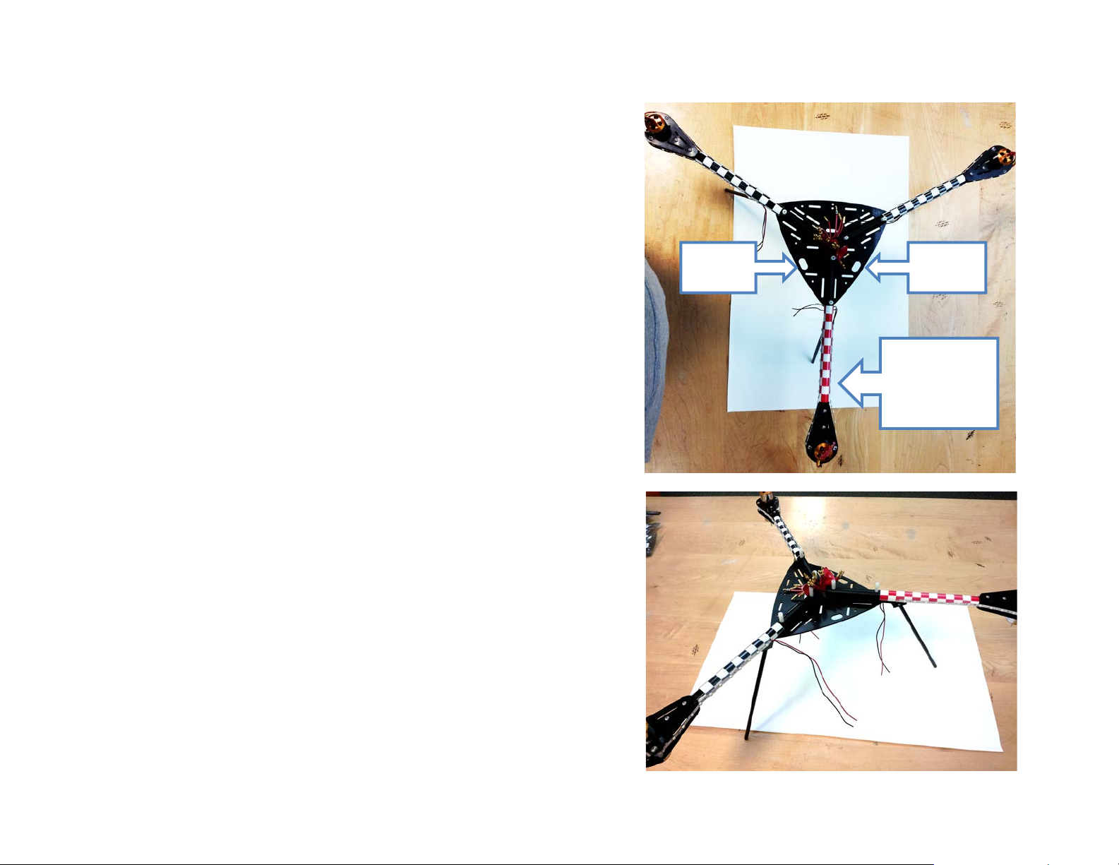
Step 8: Attach Motor/Boom Assemblies to the Bottom
Large
Large
Chassis Plate
In this step, you will attach each Motor/Boom assemb ly to the Bot tom Chassis Pla te .
(The top chassis plate is the one with the Parallax a nd Y-6 logos engraved on it, do
not use this one.) Refer to the diagram on the next page for the items needed from
your kit.
1. Orientation of the Bottom Chassis Plate does matter! Make sure to attach the
Booms in the positions shown in the picture at right. The rear Motor/Boom
assembly (with the red checkered tape if you used it) mounts on the corner
between the two large holes in the Bottom Chassis Plate.
2. Locate the correct mounting holes on the Bottom Chassis Plate to use for the
rear Motor/Boom assembly
3. Position the rear Motor/Boom assembly (item 2) in the correct place on the
Bottom Chassis Plate (item 3). The Boom Tube will rest on the Landing Gear
Mount (item 5).
4. Thread two 1-1/4” long Pan-head Screws (item 4) up through the Chassis Plate,
through the Landing Gear Assembly, and into the Boom Tube. Secure each
screw into place with a threaded 5/8” Nylon Standoff (item 1).
5. Repeat steps 3 and 4 to mount the remaining two Motor/Boom assemblies to the
other two corners of the Bottom Chassis Plate.
hole
hole
Attach Red
Boom between
largest holes
in bottom plate
Copyright © Parallax Inc. ELEV-8 Y-6 Multicopter Kit (#80100) Version 1.0 Page 13 of 31
Page 14
Copyright © Parallax Inc. ELEV-8 Y-6 Multicopter Kit (#80100) Version 1.0 Page 14 of 31
Page 15
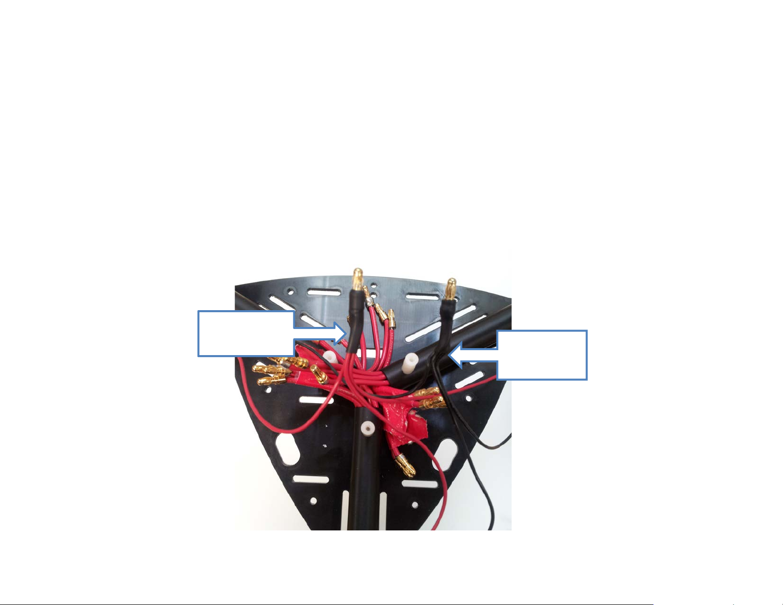
Step 9: LED Tape Leads
Solder red LED
together
Once your Booms are all mounted, it is time to connect your LED leads together and to make the adapter for plugging them into the power
harness. You will need t wo male EC3 connectors and some 3/16 inch black heat-shrink tubing for this step.
1. Bring the leads from your LED tape together in the center of your chassis.
2. Solder the red leads together in an EC3 connector.
3. Solder the black LED tape leads into another EC3 connector
4. Cut two 3/4 inch lengths of the 3/16 i nch heat-shrink tubing. Place the heat-shrink tubing over the solder joints at the base of the EC3
connectors and apply heat.
tape leads
Solder black
LED tape leads
together
Copyright © Parallax Inc. ELEV-8 Y-6 Multicopter Kit (#80100) Version 1.0 Page 15 of 31
Page 16
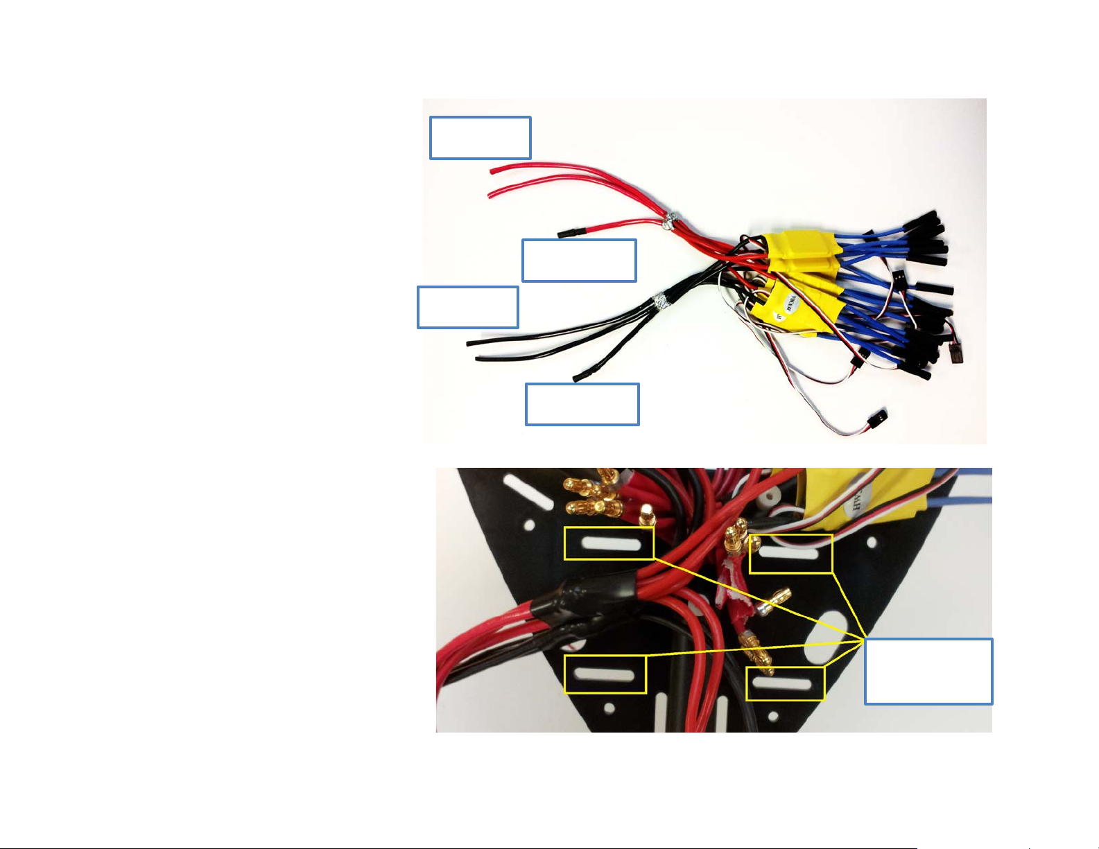
Step 10: Solder the Power Harness Together
In this step, you will solder together your ELEV-8 Y-6 Multicopt er’s
power harness. It will provide the connection between the battery
pack and the ESCs (and also the LED tape strips if you are using
them).
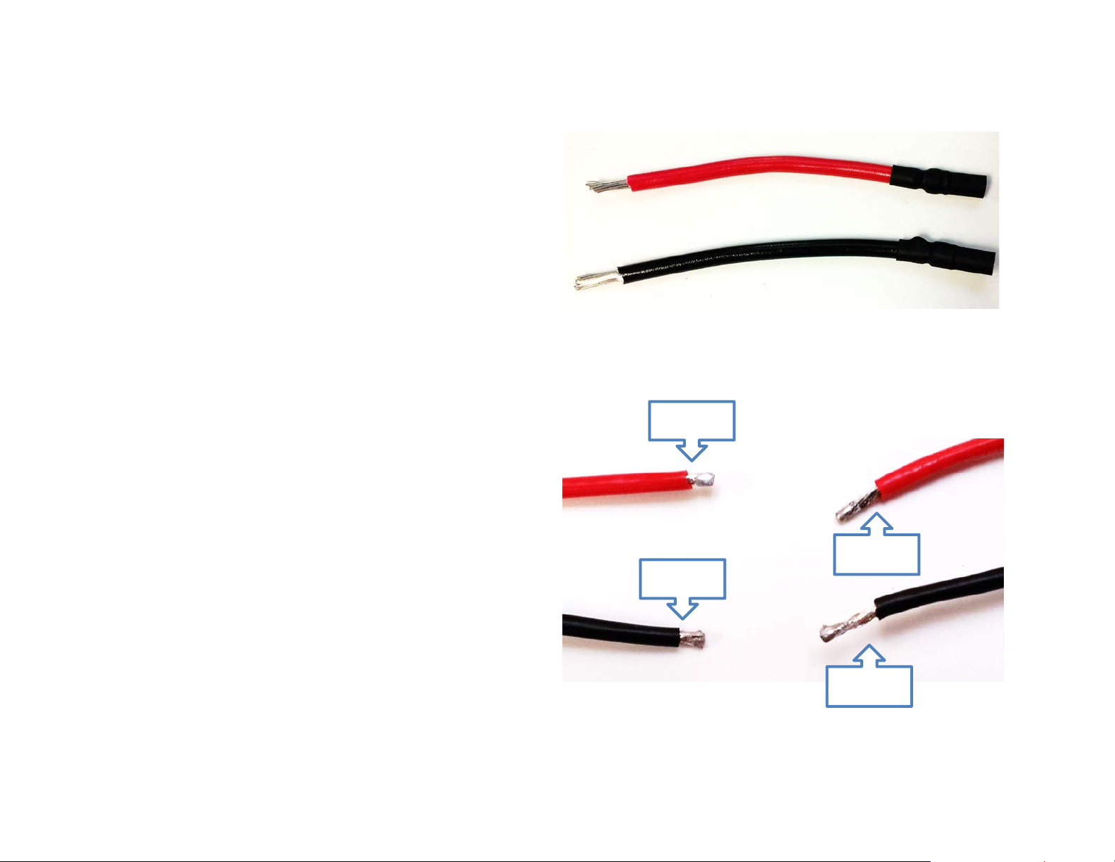
1. Find the black and red 12 AWG wires in your Electronics Kit;
these will be the power harness leads. Cut each piece in half to
give you (2) red and (2) black wires that are 6 inches long. Strip
½ inch of insulation off one end of each wire.
2. You should have two pieces of 12 AWG remaining, both 3 inches
long. Strip ½ inch of insulation off of one end, and ¼ inch off
of the other. These two wires will be used for conne cting your
LEDs to your power har ness.
3. Solder a female EC3 connector onto the ends of both 3 inch 12
AWG wires with ¼ inch of insulation removed. Now, cut two ¾
inch pieces of 3/ 16 inch black heat shrink and apply heat to
shrink the material. Your 3 inch wires should look like the ones
in the top right picture. Set these aside for now.
4. Strip an additional ¼ inch length of insulation off of t he ESC
leads, as we will need more wire exposed to make the harness
and ensure a good solder connection. The bottom right figure
shows how your ESC’s leads should look after you trim them.
Before
After
Before
After
Copyright © Parallax Inc. ELEV-8 Y-6 Multicopter Kit (#80100) Version 1.0 Page 16 of 31
Page 17
5. Solder all of the ESCs, both 6 inch 12 AWG
wires, and the 3 inch 12 AWG red leads
together. Likewise, solder all of the black
leads together as shown in the picture to the
right.
6. Cut two 1-1/2 inch lengths of ½ inch black
heat shrink. Slip a piece o f heat shrink onto
the two solder joints you just made. Ensure
the entire joint is covered by the heat shrink
before you apply heat.
7. Decide how long you want the 12 AWG
power harness leads to be. If you use the
layout shown below, you will be strapping
both batteries together using the strap holes
indicated, and you can trim the leads to
about 4 inches. If you are going to use a
custom layout to accommodate extra
electronics or anything else you may have,
decide how long to make your harness leads
and then trim them. Once the leads are
trimmed, strip 1/8 inch of insulation from the
end of each lead.
8. Locate the packet of gold bullet connectors
and plastic housings. You will need four
male bullet connectors, and two female blue
housings.
9. Solder a bullet connector onto the end of
each 12 AWG lead.
Battery (+)
LED Tape (+)
Battery (-)
LED Tape (-)
Holes for Velcro
battery straps
Copyright © Parallax Inc. ELEV-8 Y-6 Multicopter Kit (#80100) Version 1.0 Page 17 of 31
Page 18
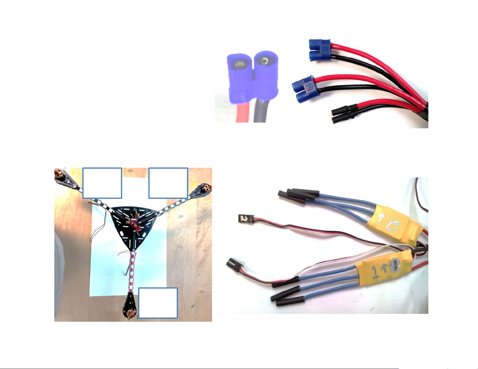
10. Insert the bullet connectors into the flattened end of the
blue housings. Insert the red leads into the D-shaped
side, which also has a (+) on the housing. Insert the
black leads into the O-shaped side, also marked with a
(-) on the blue housing. It will take so me force for the
bullet connectors to click into place.
PRO TIP: Use a flat-head screwdriver to hold the bullet
connector in the blue housing, and then use a hammer
to tap the connector into place. Give the wires a tug to
ensure they are properly seated and will not wiggle free.
11. Reposition the harness onto the chassis. Using a marker or method of your choosing, mark the ESCs so you can easily identify which lead
goes to what motor when we have the cha ssis completely assembled. Working cloc kw ise from top to bottom, we will label the motor s 1-6,
with the front left Boom’s top motor being 1, and the rear Boom’s bottom motor being 6. Ensure you mark each ESC’s body and servo lead
for an easier build later. Refer to the images below for the numbering process.
1 - Top
2 - Bottom
Copyright © Parallax Inc. ELEV-8 Y-6 Multicopter Kit (#80100) Version 1.0 Page 18 of 31
3 - Top
4 - Bottom
5 - Top
6 - Bottom
Page 19

12. Remove the harness from your chassis. Separate the motor wires coming out of the Booms and zip tie them together as shown, left.
Motor 1
Motor 2
Motor 3
Motor 4
Motor 5
Motor 6
13. Replace the harness back on the chassis, and position your ESCs where your motor wires are located per the last step for an easy hookup.
14. Once your ESCs are in position, zip tie them into place, and connect your motor leads to their ESC. For the time being, the motor to ESC
connections do not matter, as we will address this issue in a later step. Also, be s ure to connect your LED leads to their power harness leads
so that you will have light!
15. Once you have everything connected, connect one of your batteries to your power harness. You should hear beeping from your motors, and
if you are using the LED tape, they should come on. If you do not, check your connections
Copyright © Parallax Inc. ELEV-8 Y-6 Multicopter Kit (#80100) Version 1.0 Page 19 of 31
Page 20
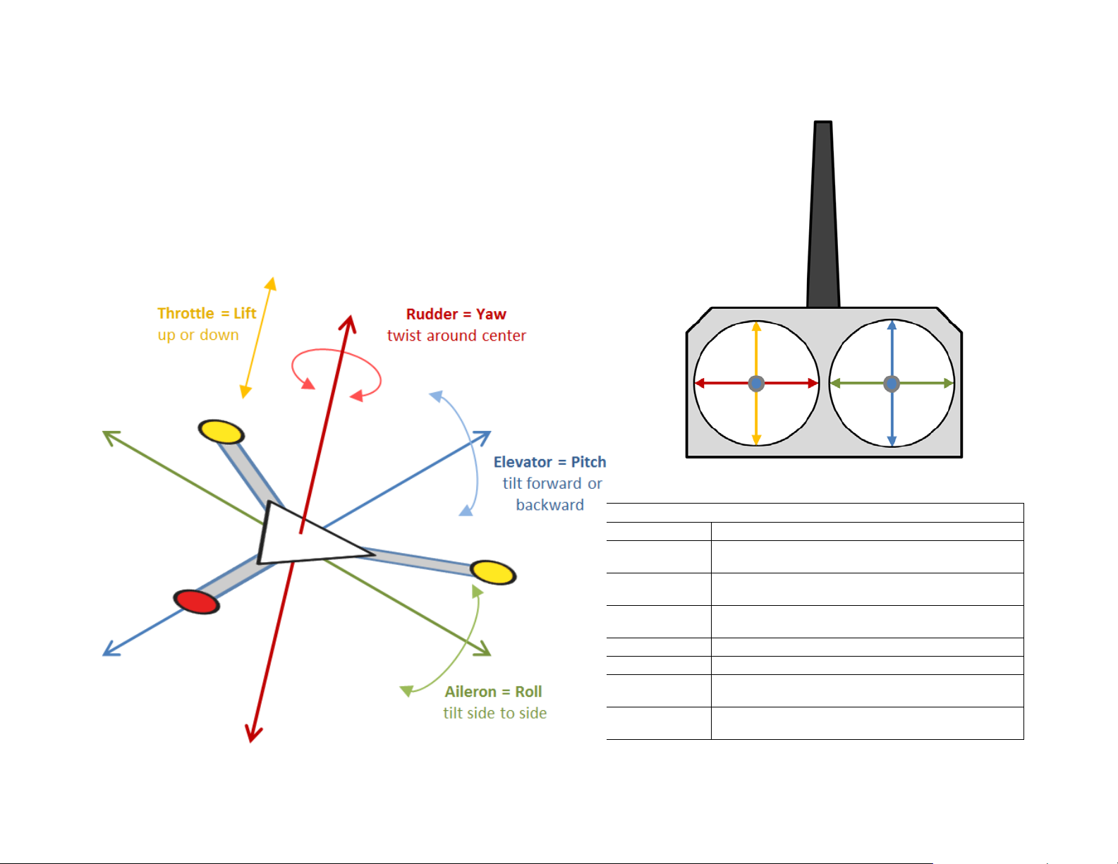
Step 11: Configure your Transmitter
Transmitter Setting Recomm endations
Box Model Type
ACRO (Plane Mode)
End point
adjustment
Set to 50% initial ly. (If the ELEV-8 still seems too
reactive, reduce to 30% until you get used to flying it.)
Dual-Rates
(D/R)
Channel
Reverse
Normal: Hi Tech Spektrum, JR brands
Reversed: Futaba br and
Trims
Centered
Sub-trims
Centered
Set Gain on 5th channel. Start with 25%, add or
subtract based on flight stability
After gaining experience, add up to 30% into aileron
and elevator
Transmitter
Throttle
Aileron
Elevator
Rudder
1. For best results, follow the Transmitter Setting Recommendations in the table
below to configure your Transmitter.
2. Refer to the diagram below to see how your Transmitter’s 2-axis joystick controls
will translate into ELEV-8 Y-6 Multicopter motion with these settings.
Copyright © Parallax Inc. ELEV-8 Y-6 Multicopter Kit (#80100) Version 1.0 Page 20 of 31
100%
Gain Adjust
Exponential
Page 21
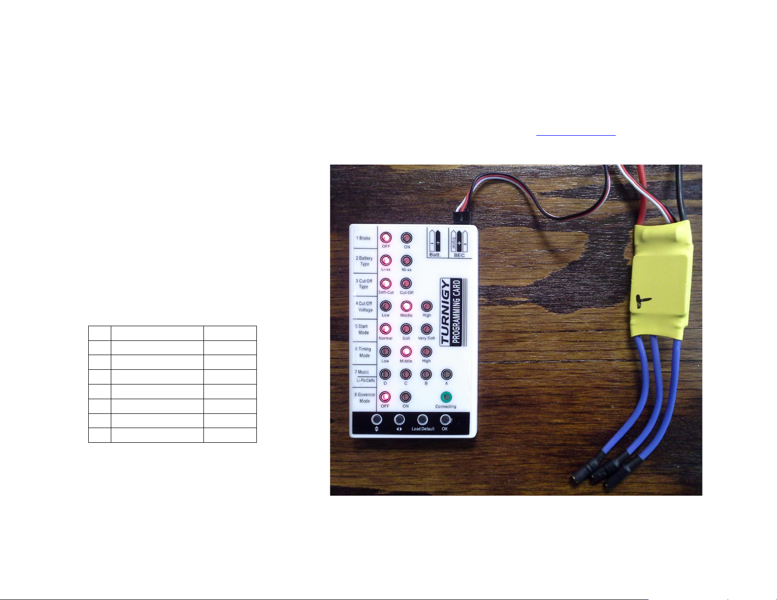
Step 12: Programming the ESC Speed Control lers
1
Brake
Off 2 Battery Type
Li-xx
3
Cut Off Type
Soft-cut*
4
Cut Off Voltage
Middle
5
Start Mode
Normal
6
Timing Mode
Middle
7
Music/Li-Po Cells
(none)
8
Governor Mode
Off
In this step, you will program the motor’s elect r onic speed controllers (ESCs) with an ESC Programming Card.
Note: The ESC Programming Card was added to kits in April 2013. They are also available separately from www.parallax.com
1. Connect your charged LiPo battery to the power
harness.
2. Connect an ESC to the ESC programming card’s BEC
port. Be sure to line up the black wire with (-), the
red wire with (+), and the white wire with (Signal).
WARNING: Do not connect to the
Programming Card’s BEC port and Batt port at
the same time; this would damage the card.
3. Set the ESC card to the configuration shown in the
picture and the table, then push OK to program the
ESC. Repeat with each ESC, using the same settings.
Be sure to cycle power between each programming
cycle.
; search “85000”.
Copyright © Parallax Inc. ELEV-8 Y-6 Multicopter Kit (#80100) Version 1.0 Page 21 of 31
* Soft-cut (also called Reduce Power) lets you know
when the multicopter’s batteries are running low. If
you set this to Cut-of f /Shut Do wn, your multicopter
will simply fall out of the sky when it reaches a low
battery level.
Page 22

Step 13: Connect the Motors and Synchronize the ESCs
After programming the ESCs, it is time to check and ensure that they are rotating in the proper direction. For this step, your R/C Controller’s
Receiver will temporarily connect directly to; and receive power from, each ESC.
Warning: Do n ot connec t a batt ery or o ther pow er source a nd an ES C to y our R/C R eceiver a t the sa me time. If you do so, you
will permanently and catastrophically damage both the ESC and Receiver.
STOP: YOU SHOULD NOT HAVE PROPELLER BLADES ON YOUR MOTORS YET! IF YOU DO, REMOVE THEM BEFORE PROCEEDING.
1. If you have not do ne so al rea dy, bind your Transm itte r to your R eceiver
as per your RC controller’s instruction manual.
2. Identify which edge of the chassis will be the fro nt of your ELEV-8 Y-6
Multicopter. If you have used the checkered sticker s and/or the LED
tapes, the front edge would be between the two black-checkered,
white-LED Booms.
3. Put a piece of tape on the output s haft of ea ch mot or, s o you can e asil y
tell the direction of rotation.
4. Connect an ESC’s 3-pin socket to the Throttle port on your Receiver.
5. Gently apply the throttle to see which direction the motor turns. Refer
to the diagram to see which direction each motor needs to turn.
6. If the motor is not turning the proper direction, disconne ct any two of
its leads, reverse them, and reconnect.
7. Repeat with ea ch ESC until all motors are turning in the correct direction
and each ESC case and lead are numbered.
8. When you are sure your motor connectio n s ar e a ll correct, apply hea t t o
finish shrinking the tubing over the motor/ESC connector joints.
Copyright © Parallax Inc. ELEV-8 Y-6 Multicopter Kit (#80100) Version 1.0 Page 22 of 31
Page 23

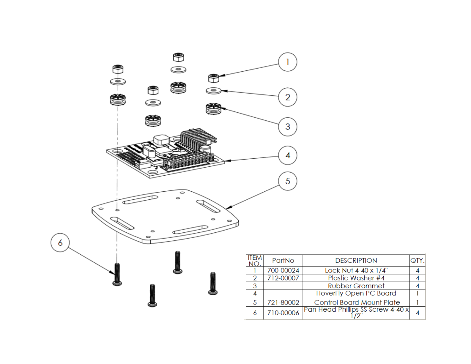
Step 14: Chassis Top Plate and Control Board Assemblies
In this step, you will prepare and attach the Chassis Top Plate. Then, you will
prepare and attach the control board to its mounting plate.
Gather the items shown in the diagrams on the next two pages. Note: the
Control Board Mount Plate has slots around all four edges.
1. Pull all the ESCs’ 3-pin leads together towards the front of the chassis.
2. Referring to the diagram on the next page, locate the correct holes in the
Top Chassis Plate for the ½ inch s crews to come up through, and then put
the nylon hex nut onto them and hand tighten.
3. Thread the ESCs’ 3-pin leads up through the top oval slot, as shown in the
picture at right.
4. Attach the Top Chassis Plate to the standoffs on top of the Booms using six
¼ inch Black Pan-head Screws.
5. For the Control Board Assembly, refer to the diagram on page 25. Blue
rubber grommets are included with the Hoverfly Control Board. Insert a
rubber grommet (item 3) into the large mounting holes on each corner of
the board. These grommets reduce vibrations transferred to the Control
Board during flight.
6. Insert each ½ inch Pan-head Screw ( item 6) up through the Mounting plate
(item 5), through the grommet (item 3), and then install a Plastic washer
(item 2) and a Lock nut (item 1). Do not over tighten the locknut.
Hand tightening just enough so that the board does not move around works
best.
Copyright © Parallax Inc. ELEV-8 Y-6 Multicopter Kit (#80100) Version 1.0 Page 23 of 31
Page 24

Copyright © Parallax Inc. ELEV-8 Y-6 Multicopter Kit (#80100) Version 1.0 Page 24 of 31
Page 25
31500
Copyright © Parallax Inc. ELEV-8 Y-6 Multicopter Kit (#80100) Version 1.0 Page 25 of 31
Page 26

Step 15: Reprogram the Control Board Firmwar e for Y-6
In this step you will program the Control Boar d to know it is in a Y-6 configura ti o n.
1. If you have not done so alread y, go t o the website listed here and download the Hoverfly Firmware Update Client:
http://www.hoverflytech.com/Software_Updates.html
2. Once you have the software instal led and opened, connect your Contr ol Board to your P C. Follow the ons creen instructions to update your
board’s firmware for the Y-6 configuratio n.
3. Be sure to set Select Board to Hoverfly Open, and Select Mode to Y6.
Copyright © Parallax Inc. ELEV-8 Y-6 Multicopter Kit (#80100) Version 1.0 Page 26 of 31
Page 27

Step 16: Mount the Control Board Assembly to the Chassis
In this step you will enclose the Control
Board within its protective Top Plate,
and then mount the assembly on to
the completed Y-6 chassis. To begin
the hardware assembly, gather the
items listed on the diagram on the next
page.
1. Find the arrow on the Control
Board silkscreen, as shown at
right. This arrow points to the
front of the Control Board, which
must be facing the same direction
as the front of the chassis.
2. Referring to the diagram on the
next page, set the Control Board
Assembly over the ½ inch screws
that are protruding from the Top
Chassis Plate, aligning the front of
the control board with the front of
the chassis.
3. Install and hand tighten the 5/8 inch Nylon Standoffs. This secures the Control Board Mount Plate to the Top Chassis Plate.
4. Align the Control Board Top Plate over the Control Board. The small hole near the center of the Top Plate is for a light pipe. Ensure this hole
is located above the LED on the Control Board so that you will be able to see the status of the Control Board when the Top Plate is inst alled.
5. Place the Top Plate (item 3) on top of the 5/8 inch standoffs and secure it using ½ inch screws (item 2).
6. Insert the Light Pipe (item 1) into its hole in the Control Board Top Plate. Trim the light pipe so that it rests just above the LED on the Control
Board.
7. Mount your R/C Receiver to the chassis Plate using zip ties, double sided tape, or a method of your choosing. Ensure that you refer to your
R/C Receiver’s manual for best placement recommendations.
Copyright © Parallax Inc. ELEV-8 Y-6 Multicopter Kit (#80100) Version 1.0 Page 27 of 31
Page 28

Copyright © Parallax Inc. ELEV-8 Y-6 Multicopter Kit (#80100) Version 1.0 Page 28 of 31
Page 29

Step 17: Control Board Connections
In this step, you wi ll co nne ct yo ur E SCs a nd R ece i ver to yo ur Co ntr ol Bo ard . The Rece ive r co nnects to the
Receiver Port’s 2x9 male header on the left edge of the Control Board. The Electronic Speed Controllers
connect to the ESC Port’s 2x12 male header on the front edge of the Control Board.
1. Connect the Receiver to the Receiver Port, with the five signal connections listed below. Use the 3wire extension cables included in the ELEV-8 Electronics Kit.
A = Aileron
T = Throttle
R = Rudder
E = Elevator
G = Gear (ON: EPA value is Primary Gain, Altitude Hold is off.)
(OFF: EPA value is Altitude Hold Gain, Altitude Hold is on.)
2. Connect each motor’s ESC to the corresponding pins on the ESC port.
Match the motor numbers at left to the port numbers below.
3. Double-check your connections – it’s easy to make a mistake here.
Copyright © Parallax Inc. ELEV-8 Y-6 Multicopter Kit (#80100) Version 1.0 Page 29 of 31
Page 30

Step 18: Mounting the Propeller Blades
1045C
Only mount the propeller blades when you are ready to fly.
There are two different types of slow flyer propeller blades in the ELEV-8
Electronics Kit: Counterclockwise, (CCW, marked 1045C) and Clockwise (CW,
marked 1045CR). The correct type of blade must be used on each motor f or the
ELEV-8 to fly. See the drawing below for lab el l ocatio n; the blades are roundedside-up.
1. Disconnect the battery from the Power Harness.
2. Refer to the diagram on this page for the correct placement of each blade.
3. Connect each blade to its m otor, referring t o the diag ram on the next page.
The Blade (item 2) should be mounted rounded-side-up, seat ed on a Cone
Lock (item 3) over a Collet (item 4).
IMPORTANT! Even though the bottom motors are mounte d upsidedown, the propellers on them must be mounted righ t-side up. So,
ALL the propellers on your Y-6 will have the rounded side up.
4. Finger-tighten t he Propeller Nut (item 1), the n use a Hex Key to tighten ¼
turn more.
1045CR
Copyright © Parallax Inc. ELEV-8 Y-6 Multicopter Kit (#80100) Version 1.0 Page 30 of 31
Page 31

Copyright © Parallax Inc. ELEV-8 Y-6 Multicopter Kit (#80100) Version 1.0 Page 31 of 31
 Loading...