

Page 1

Web Site: www.paral lax.com
Forums: forums.parallax.com
Sales: sales@parallax.com
Technical: support@parallax.com
Office: (916) 624-8333
Fax: (916) 624-8003
Sales: (888) 512-1024
Tech Support: (888) 997-8267
XBee 5V/3.3V Adapter (#32401)
This low cost XBee 5V/3.3V Adapter comes in partially assembled kit form and provides a cost-effective
solution for interfacing your microcontroller to any XBee or XBee Pro module. A voltage regulator and
74LVC244A buffer is included onboard for safe interfacing to a 5 V supply, allowing for easy compatibility
with any Parallax microcontroller.
Features
Onboard 3.3 V regulator and 5 V to 3.3 V logic converters
y
y Four status indicator LEDs for Power, RSSI, Associate and
mode (sleep/ON)
y Converts XBee 2 mm pin spacing to 0.100” pin spacing
y Provides easy pluggable wire or solder connections
y Pin-out compatible with other Parallax XBee Adapter
Boards
y Partially assembled kit form for flexible configuration
y Compatible with all Parallax microcontrollers
Key Specifications
Power requirements: 3.3–5 VDC
y
y Communication: Serial pass-through to XBee module
y Operating temperature: -40 to 158 °F (-40 to 70 °C)
y Dimensions (with headers attached): 1.51 x 1.00 x 0.58 in
(38.3 x 25.6 x 14.8 mm*)
Kit Contents
(1) XBee 5V/3.3V PCB (SMD components pre-soldered)
y
y (2) 10-pin 2mm sockets
y (1) 40-pin SIP header
Tools Required
Soldering iron (always wear safety glasses when soldering)
y
y Solder (some soldering experience required)
y Flux
y Diagonal cutters or hobby knife
Copyright © Parallax Inc. XBee 5V/3.3V Adapter (#32401) v1.2 7/27/2010 Page 1 of 6
Page 2

Assembly Instructions
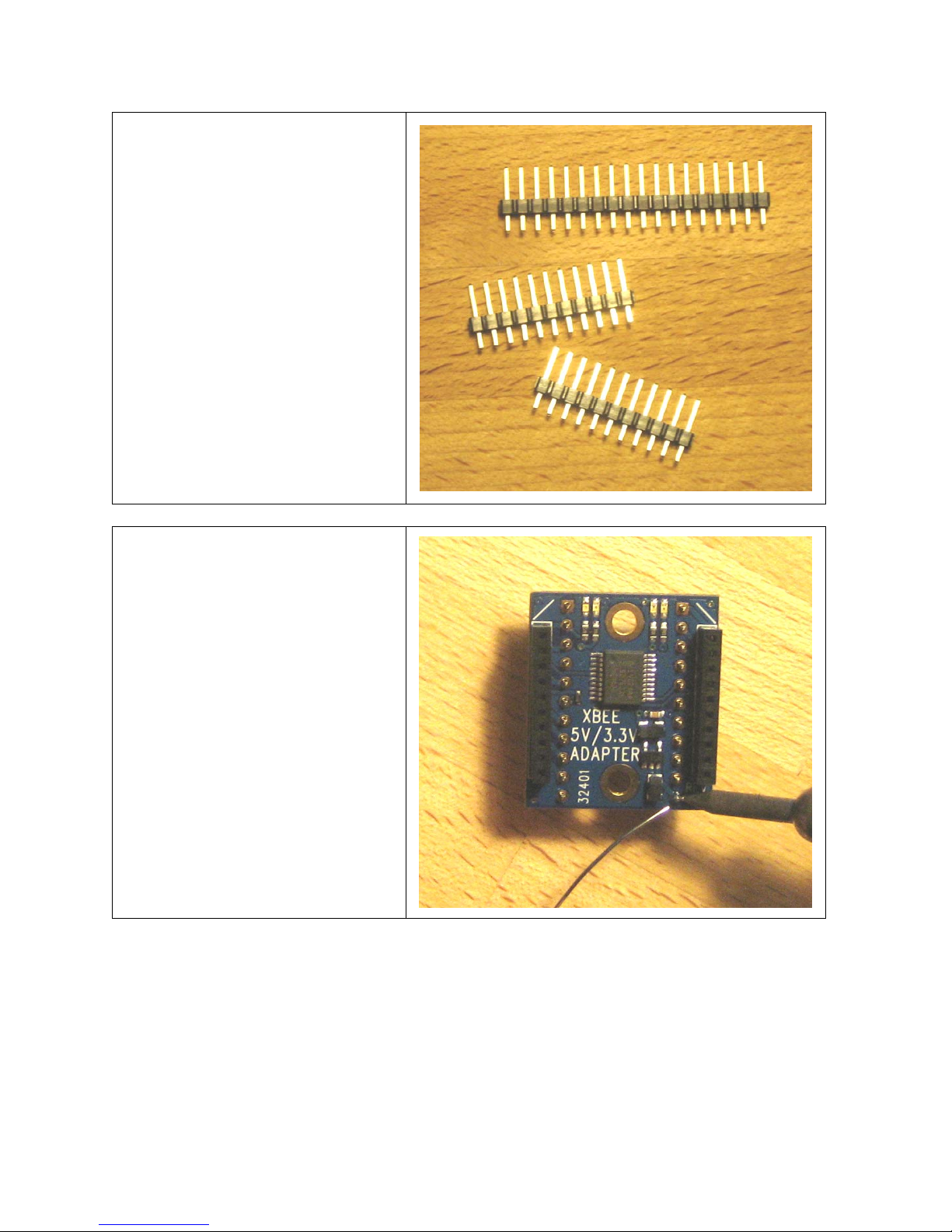
Step 1:
Check to ensure your kit contains the
following parts as shown in the photo.
Step 2:
Install the 2mm sockets on top of the
PCB as shown, and then solder them in
place from the bottom side of the board.
Copyright © Parallax Inc. XBee 5V/3.3V Adapter (#32401) v1.2 7/27/2010 Page 2 of 6
Page 3
Step 3:
Using a hobby knife or a pair of
diagonal cutters, cut two 11-pin headers
from the 40-pin header. Extra header
material is included in case of mistake
or damage.
Step 4 (optional):
Insert the two 11-pin SIP headers into
the bottom of the adapter board as
shown and solder them in place from
the top.
This step is optional in that you can
solder wires directly to the pads if
desired.
Copyright © Parallax Inc. XBee 5V/3.3V Adapter (#32401) v1.2 7/27/2010 Page 3 of 6
Page 4

LED Status Indicators
The XBee 5V/3.3V Adapter has four LEDs onboard for easy feedback of module status. These four LED
colors and functions are listed in the table below:
LED Color Function
Blue Power`
Yellow Module ON (not in standby)
Red RSSI
Green Associate
Connecting and Testing
While the XBee RF Modules are 3.3V devices, the XBee 5V/3.3V Adapter provides a means to interface
your XBee with a BASIC Stamp or other 5 V microcontroller. The DIN, DOUT and /RTS pins interface to
the XBee through a 74LVC244A buffer, safely regulating 5 V signals to 3.3 V.
The supply voltage (whether 3.3 V or 5 V) should be connected to the VDD pin on the adapter board,
which is run through a 3.3V regulator and supplied to the XBee through the VCC pin. Do not connect
an additional external voltage supply to the VCC pin if power is already applied through VDD.
This could damage to your XBee module.
Caution: Voltage regulator supply current limitation.
The FAN2500S33X regulator used on Rev A of this adapter is rated at 100 mA continuous, 300 mA peak
current. VCC may be used as a 3.3 V supply output, but be sure that you budget enough current for
your XBee module as well as any other device you might supply through this regulator. The regular XBee
modules (Series 1 and Series 2) draw less than 55 mA, but XBee Pro modules can draw over 200 mA
when in a continuous-transmit state. While this adapter board can supply enough current for the
intermittent transmissions of XBee Pro modules typical to many common uses, applications requiring
continuous, sustained transmissions from XBee Pro modules would be better suited to the XBee SIP
Adapter (#32402), or the XBee Adapter Board (#32403) with an external regulator (not included).
Module Dimensions
Copyright © Parallax Inc. XBee 5V/3.3V Adapter (#32401) v1.2 7/27/2010 Page 4 of 6
Page 5

Connection Diagrams
The example code below utilizes a pushbutton connected to Pin 13 on the transmitter board, and an LED
connected to Pin 13 the receiver board, while the connection for the XBee 5V/3.3V Adapter remains the
same for both boards.
Copyright © Parallax Inc. XBee 5V/3.3V Adapter (#32401) v1.2 7/27/2010 Page 5 of 6
Page 6

BASIC Stamp® 2 Program Examples
The sample code below demonstrates simple communication using two XBee modules interfacing with
two BASIC Stamp 2 microcontrollers. The first program, XBeeTX_PbLed.bs2 sends the state of a
pushbutton connected to P13 while the second program, XBeeRX_PbLed.bs2 receives the state of the
pushbutton, displays it on the Debug Terminal, and turns on an LED if the button is pressed. Both
programs can be downloaded from the 32401 product page at www.parallax.com
' {$STAMP BS2}
' {$PBASIC 2.5}
' XBeeTX_PbLed.bs2
' Sends state of an active-high pushbutton connected to P13
TX PIN 14 ' XBee DIN pin
DO
SEROUT TX, 84, [BIN IN13, CR] ' Sends state of pushbutton
PAUSE 250 ' Short pause
LOOP ' Loop forever
' {$STAMP BS2}
' {$PBASIC 2.5}
' XBeeRX_Simple.bs2
' Received state of pushbutton, displays state in Debug Terminal
' and turns on an LED if the button is pressed.
RX PIN 15 ' XBee DOUT pin
PbState VAR Bit ' Variable space for pushbutton state
DO
SERIN RX, 84, [BIN PbState] ' Receives pushbutton state
DEBUG HOME, ? PbState ' Displays state in Debug Terminal
IF PbState = 1 THEN HIGH 13 ELSE LOW 13 ' LED on if pressed/off if not pressed
LOOP ' Loop forever
.
Copyright © Parallax Inc. XBee 5V/3.3V Adapter (#32401) v1.2 7/27/2010 Page 6 of 6
Page 7

 Loading...