

Page 1
599 Menlo Drive, Suite 100
Rocklin, California 95765, USA
Office: (916) 624-8333
Fax: (916) 624-8003
General: info@parallaxinc.com
Technical: support@parallax.com
Web Site: www.parallax.com
Educational:
http://www.parallax.com/html_pages/edu/
BASIC Stamp HomeWork Board
#29158 10-pack of Breadboard version
#29157 10-pack of Through-Hole version
Introduction
It’s not often that we start technical documentation with a bit of marketing punch. If you like the low cost of a
BASIC Stamp Rev. D (retails ~$34) and the idea of a half-price BASIC Stamp 2 / Board of Education (retails
~$109) then the BASIC Stamp HomeWork board is the ticket for your class. This is the least expensive way to
get a large educational group started with the BASIC Stamp.
The HomeWork Boards were created exclusively for educators to send home with students with these uses in
mind:
• BASIC Stamp-related homework assignments
• Dedicated science-fair, contest or hobby projects
• Students who express personal interest in further developing their BASIC Stamp projects but can’t have
their own Board of Education / BS2 due to it’s higher cost
Since it’s less expensive than the Board of Education / BS2 module, can the board be used for Stamps in Class
experiments? Possibly, with the following considerations:
• Servo connection ports for robotics are not included on the HomeWork Board. It’s possible to use
male/male headers for servo connections with a second power supply jumpered to the HomeWork
Board to control servos.
• 220 ohm resistors are built into each of the 16 I/O pins for current protection so the PBASIC interpreter
cannot be easily damaged. This protects the BASIC Stamp from over-current conditions but also
slightly changes the behavior of the Stamps in Class experiments if used on this board based on the
command being used.
• Stamps in Class circuit pictorials do not match the HomeWork Board. Again, minor workaround once
you understand the difference between the power supply options.
• Power supply is from a 9V battery, not the wall pack.
• Current supply from the on-board regulator is limited to 50 mA versus the Board of Education’s amp or
more.
However, these cost-reducing limitations do not limit the use of the HomeWork Board for other projects. In fact,
the minimalist design is simple to use and entirely flexible for most projects.
Parallax, Inc. • BASIC Stamp HomeWork Board ver 1.1 Page 1
Page 2

Package Contents
The BASIC Stamp HomeWork Board is sold only in quantities of 10. The reason for this is that the board is
intended for the educational market only, to be purchased by educators for use in their classrooms. The kit
includes only the boards – nothing else.
BASIC Stamp HomeWork Board Hardware Design
BASIC Stamp HomeWork Board uses the BASIC Stamp 2 surface-mounted directly to the printed circuit board.
The BASIC Stamp 2 has a wide variety of available support hardware, code examples and applications. Further,
it performs most of the same functions of the newer BASIC Stamps though with less speed and memory. The
BASIC Stamp 2’s technical specifications are shown below (Table 1). Also review the hardware (Figure 1) and
schematic (Figure 2).
Table 1
BASIC Stamp
HomeWork Board
Specifications.
Microcontroller: PIC16C57 surface mount
Speed: 20 MHz / ~4,000 instructions per second
EEPROM: 2K bytes (program and data)
Program Length: 500 lines of PBASIC
RAM (variables): 32 bytes (6 for I/Os and 26 for variables)
Input / Outputs: 16 (up to 17 RS-232 communication ports)
Source / Sink Current: 50 mA / 50 mA
Serial Communication: 300-50K baud I/O
Current Requirements: 7 mA running, 50 uA in sleep
PC Interface: Serial port
Power Supply:
Environment:
HomeWork Board Size: 3” x 4”
Project Area: Built-in breadboard on StampLab
Microcontroller: PIC16C57 surface mount
Speed: 20 MHz / about 4,000 instructions per second
EEPROM: 2K bytes (program and data)
Program Length: ~500 to 600 lines of PBASIC
5 V through an LM2936 regulator from a 9V
transistor battery
32 to 158° F (0 to 70° C), 70% noncondensing humidity
Parallax, Inc. • BASIC Stamp HomeWork Board ver 1.1 Page 2
Page 3
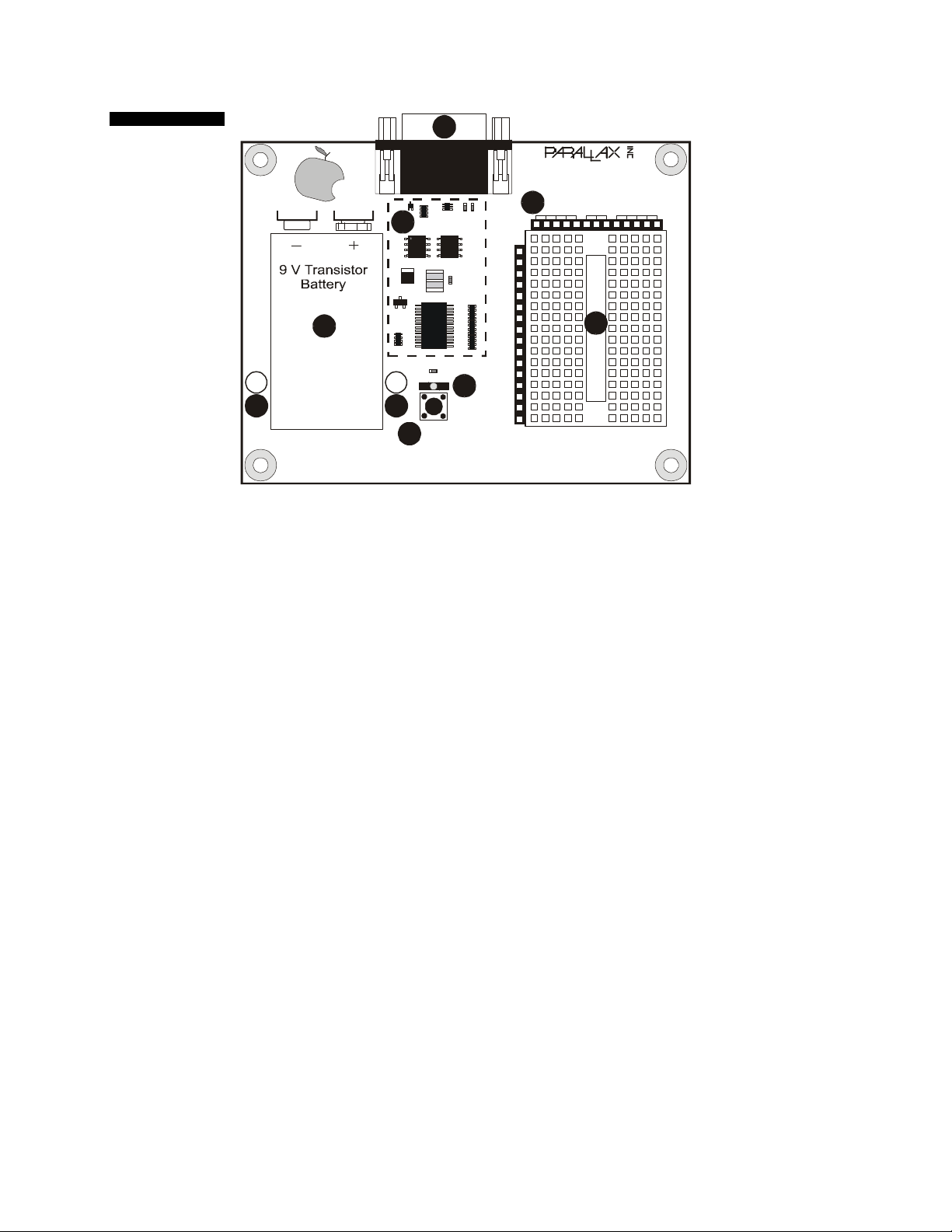
Figure 1
B
StampLab printed
circuit board keyed
with part
identifications.
S
T
A
M
P
i
n
S
C
L
A
S
S
A
P15
P14
P13
P12
P11
P10
H
Power
GG
Reset
F
BASIC Stamp HomeWork Board
P9
P8
P7
P6
P5
P4
P3
E
P2
P1
P0
(916) 624-8333
www.parallaxinc.com
www.stampsinclass.com
C
Vdd VssVin
X3
X4
D
© 2002
Rev A
A. BASIC Stamp 2 Module. The BASIC Stamp is comprised of several components: PIC16C57-20/SS
- a Microchip 2K 8-bit microcontroller programmed with the the BASIC Stamp “Interpreter” that runs
the Parallax BASIC Stamp code like a mini operating system; the 24LC16B EEPROM - a Microchip
2K EEPROM (electrically erasable programmable read-only memory) with a user-modifiable readonly memory (ROM) that can be reprogrammed with your BASIC Stamp code; a 20 mHz resonator
to provide an accurate clock source for the BASIC Stamp; 220 Ohm resistors across the I/O pins to
provide current protection for mistake wiring; an LM2936 voltage regulator which provides 50 mA for
the BASIC Stamp and your circuits powered from the breadboard’s Vdd connection.
B. DB-9 Female. The DB-9 port connects via serial cable to your PC’s serial port. This port is used to
download programs to your BASIC Stamp and for the BASIC Stamp to send data back to the PC.
C. Power and Ground Connections. Vdd is regulated 5V, Vin is 9V from the transistor battery, Vss is
ground.
D. Breadboard. Two areas of 5 column x 17 row breadboard project area. Connections are horizontal
separated by the trough.
E. Power Button. Illuminated when the BASIC Stamp is running a program only.
F. Reset Circuit. Reset the BASIC Stamp by pressing this button.
G. Battery Tie-Downs. If using the HomeWork Board Through-Hole Version for projects involving high-
vibration (on R/C airplanes, robots, etc.) a “zip-tie” can hold the battery firmly to the board if looped
through these holes.
H. Power Supply. Accepts a 9V battery.
Parallax, Inc. • BASIC Stamp HomeWork Board ver 1.1 Page 3
Page 4
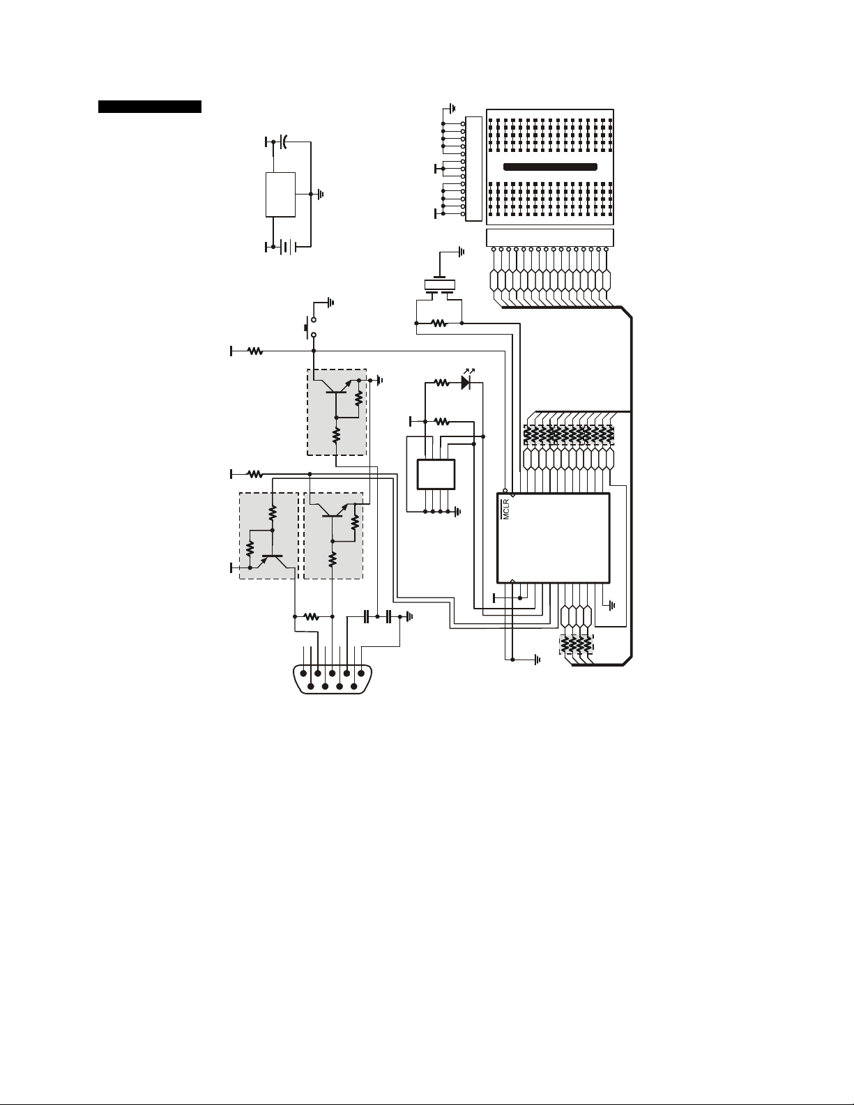
Figure 2
BASIC Stamp
HomeWork Board
Schematic
Vin
Vdd
20 MHz
N/C
Vdd
A0A1A2
R1
R2
RN1-2
Dat
Clk
24LC16B
Vss
Vss
13
12
11
10
9
8
7
6
5
4
3
2
1
X3
X4
16
Vss
P9
P10
P11
P12
P13
P14
P15
Ω
10k
Ω
100
D2
0Ω
Ω
PowerLED
4.7k
P15
26
Vss
RC7
OSC1
OSC2
U1
VSS
RTCCI2VDD3VDD
1
4
Vdd
0Ω
RN5
RN4
22
22
P8
P9
P10
P11
P12
P13
P14
RC0
RC1
RC2
RC3
RC4
RC5
RC6
(PBASIC2/SS)
PIC16C57-20/SS
RA05RA16RA27RA38RB09RB110RB211RB312RB4
P0P1P2
Vss
Breadboard
123456789101112131415
P0P1P2P3P4P5P6P7P8
0Ω
RN3
22
P4
P5P6P7
15161718192021222324252827
RB5
RB6
RB7
VSS
13
14
Vss
P3
0Ω
RN2
22
µF
C1
10
+
Vdd
3
VOUT
VIN
VR1 LM2936
1
Vin
9V Transistor
Ω
RN1-4
4.7k
Ω
4.7k
RN1-3
Vdd Vdd
Ω
10k
Ω
10k
Vdd
2
VSS
Battery
PB1
Reset
1/2 UM11TN
DTA114EETL
1/2 UM11TN
Ω
RN1-1
4.7k
162738495
Vss
Vss
Vss
Ω
10k
Ω
10k
Ω
10k
Ω
10k
Vdd
U2
Vss
µF
µF
C4
C3
0.1
0.1
J2
DB9 Female
Power Consumption and Battery Life
Parallax normally designs BASIC Stamp boards with power jacks for wall transformers. Wall transformers provide
plenty of power but they are not as portable for science fairs, robots and environmental datalogging. Considering
that the BASIC Stamp draws only small amounts of current it could be deployed in a remote location and run
from a battery for a long time.
The BASIC Stamp has commands for reduced power consumption, but what about the power indicator LED? It
could drain the battery in a day or two by itself if being used to indicate a power supply! LEDs consume current,
typically 10-12 mA. Removing the LED wasn’t an option since it discloses the common technical support problem
of a missing power supply.
The solution was to connect BASIC Stamp HomeWork Board’s power LED to the “clock” line of the BASIC
Stamp’s EEPROM. The EEPROM’s clock line is active only when the BASIC Stamp is actually running a
program. Moreover, the BASIC Stamp HomeWork Board’s power LED is a low current LED consuming only
about 2 mA.
Parallax, Inc. • BASIC Stamp HomeWork Board ver 1.1 Page 4
Page 5
MilliAmp hours is a statistic measuring the amount of energy stored in a battery. For
example, if you have a 1 mA-hr battery and a project drawing 0.5 milliamps, the battery
will last for two hours. A typical 9V Duracell alkaline transistor battery provides about
565 milliAmp hours of energy.
If the BASIC Stamp is being used in a project where at least some small amount of time is spent doing nothing
you can put it in a low-power mode to extend battery life using the SLEEP command (Table 2). The duration
which you put the BASIC Stamp to SLEEP is accurate to ± 1% at 75° F and can ranges from 2.3 seconds to 18
hours (you can “wake up” and go back to sleep after 18 hours). By comparison, the PAUSE command is simply a
delay in a PBASIC program yet the BASIC Stamp continues to draw full operating current. See the BASIC Stamp
Windows Editor on-line help for all the details on the SLEEP and PAUSE commands.
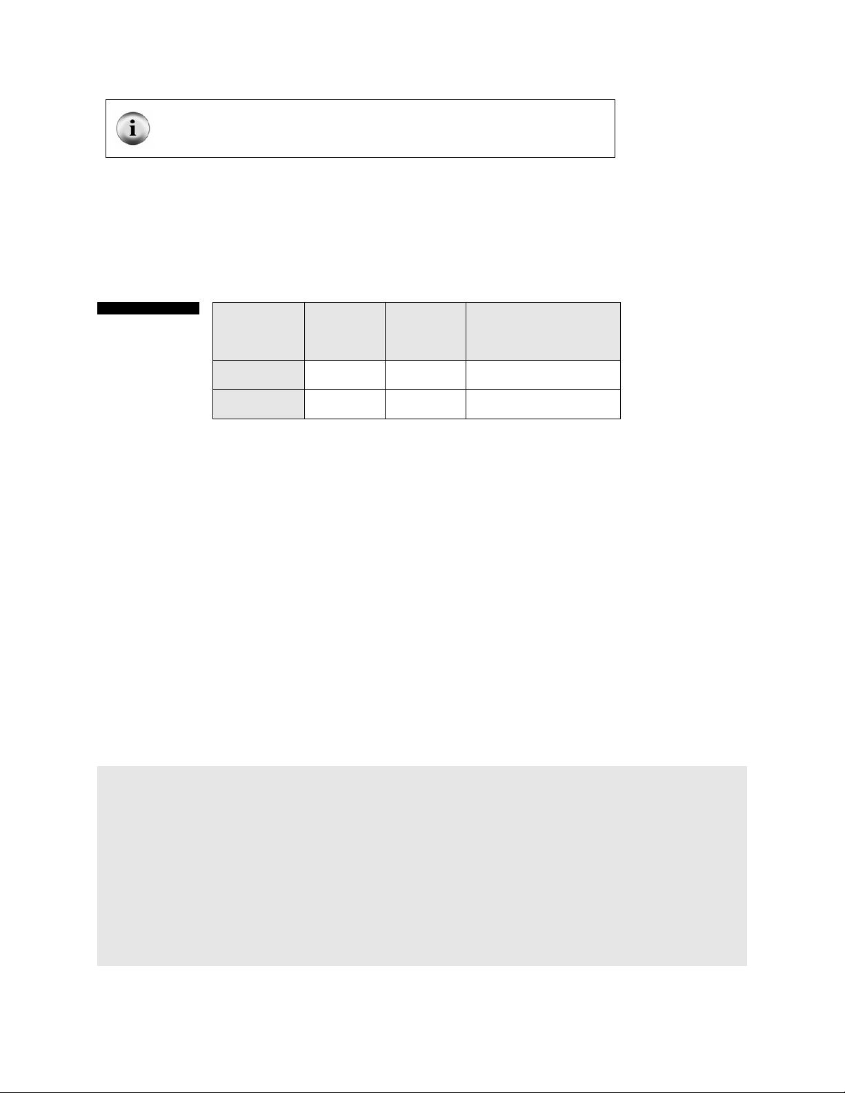
Table 2
BASIC Stamp 2
and Power LED
current draw
during different
modes of
operation.
Note: 1 mA is 1/1,000th of an Amp. 1 microAmp (µA) is 1/10,000th of an Amp.
PAUSE Mode
SLEEP Mode 40 µA 0 mA (565 mAh/(40 µA/1000
BASIC
Stamp
Current
Draw
8 mA 2 mA (565 mAh/10 mA)
Power LED
Current
Draw
Possible Battery Life
= 56.5 hours
mA) = 14,125 hours
Maybe putting a BASIC Stamp to SLEEP permanently only demonstrates that a 9V battery can last almost two
years if you wake the BASIC Stamp once in a while. In reality, projects need to wake up and provide current to
“loads” like LEDs and other chips used in your project. If you know the current draw of the individual components
and how long they are activated you can make an educated guess at total current consumption and battery life. If
you’re only visiting your North Pole weather station annually even a small battery can provide a long lifespan for
the BASIC Stamp, not to mention larger batteries with more milliamp hours.
To clarify the BASIC Stamp’s different power consumption operating scenarios and their effects on battery life
review the following two programs in conjunction with Table 2. Downloading and understanding these programs
will require a look ahead to future chapters, so be prepared to re-visit this section.
Both programs have the same result. The BASIC Stamp will send numbers to the BASIC Stamp Windows Editor
debug window and then go into a period of inactivity for a second. With the PAUSE example the power LED
remains on because the EEPROM is still communicating with the BASIC Stamp interpreter chip, but with the
SLEEP example the EEPROM is shut down and the power LED is off.
With this example the Power LED remains on when the PAUSE command is executed. Current consumption
remains at 10 mA.
' POWER DEMO - PAUSE.BS2
' Demonstrating the power LED with SLEEP command
' {$STAMP BS2}
' I/Os, Constants and Variable definitions
loopCounter VAR Byte
' Main Program
Start:
FOR loopCounter = 0 to 99
DEBUG Home, "loopCounter =", dec loopCounter
NEXT
PAUSE 1000
GOTO Start
Parallax, Inc. • BASIC Stamp HomeWork Board ver 1.1 Page 5
Page 6

With the SLEEP example the Power LED turns off when the SLEEP command is being executed because the
EEPROM is inactive. Current consumption is 10 mA while the loop is being executed but drops to 40 µA during
the SLEEP command.
' POWER DEMO - SLEEP.BS2
' Demonstrating the power LED with SLEEP command STeve
' {$STAMP BS2}
' I/Os, Constants and Variable definitions
loopCounter VAR Byte
' Main Program
Start:
FOR loopCounter = 0 to 99
DEBUG Home, "loopCounter =", dec loopCounter
NEXT
SLEEP 1
GOTO Start
Precautions
Be alert to static sensitive devices and static-prone situations. The BASIC Stamp, like other integrated circuits,
can be damaged by static discharge that commonly occurs touching grounded surfaces or other conductors.
Environmental conditions (humidity changes, wind, static prone surfaces, etc) play a major role in the presence of
random static charges. It is always recommended to use grounding straps and anti-static or static dissipative
mats when handling devices like the BASIC Stamp. Since you don’t have a dissipative mat, touch a grounded
surface after you have approached your work area. This isn’t as critical as you might think but being prudent only
protects your hardware.
Before building circuits, disconnect the battery.
Parallax, Inc. • BASIC Stamp HomeWork Board ver 1.1 Page 6
Page 7

Quick Start Programming Guide
This chapter is a quick start guide to connecting the BASIC Stamp to the PC and programming it. Without even
knowing how the BASIC Stamp functions, you should be able to complete the exercise without difficulty.
Connecting Serial Cable and Power Supply
Connect the 9-pin female side of a serial cable to an available serial port on your computer. Connect the 9-pin
male side of the cable to the DB9 connector to BASIC Stamp HomeWork Board. Plug in a 9V transistor battery to
BASIC Stamp HomeWork Board (Figure 3).
Figure 3
Connect 9V
battery and the
serial cable to your
StampLab.
S
T
A
M
P
i
n
S
C
L
A
S
S
Alkaline Battery
Powercell
Power
Reset
BASIC Stamp HomeWork Board
X3
X4
P15
P14
P13
P12
P11
P10
P9
P8
P7
P6
P5
P4
P3
P2
P1
P0
(916) 624-8333
www.parallaxinc.com
www.stampsinclass.com
Vdd VssVin
Rev A
© 2002
The serial cable is straight-through and it is not a null modem cable. If you have null modem cables laying around
put them away so you don’t create an unnecessary problem.
Install the BASIC Stamp Windows Editor Software
The BASIC Stamp Windows Editor is available for download from www.parallaxinc.com. Download and install as
shown in Figures 4 through 8.
BASIC Stamp Windows Editor is frequently upgraded and improved with additional features. It is often a good
idea to visit www.parallaxinc.com/editor to download the most recent version.
Parallax, Inc. • BASIC Stamp HomeWork Board ver 1.1 Page 7
Page 8

Figure 4
Software install
Step 1 – just click
“Next”.
Figure 5
Software install
Step 2. Choose
“Typical” for a
installation.
standard
Parallax, Inc. • BASIC Stamp HomeWork Board ver 1.1 Page 8
Page 9

Figure 6
Software install
Step 3. Click
“Install” and finish
the process.
Figure 7
Finish the
installation
process..
Downloading a Program
The BASIC Stamp Windows Editor was designed to be easy to use and mostly intuitive. Those who are familiar
with standard Windows software should feel comfortable using the BASIC Stamp Windows Editor (Figure 9).
The editor consists of one main editor window that can be used to view and modify up to 16 different source code
files at once. Each source code file that is loaded into the editor will have its own tab at the top of the page
labeled with the name of the file. Source code that has never been saved to disk will default to “Untitled#”; where
# is an automatically generated number. A user can switch between source code files by simply pointing and
clicking on a file’s tab. File | Save allows the naming and saving of a file.
After entering the desired source code in the editor window, selecting Run -> Run (or pressing Ctrl-R) will
tokenize and download the code to the BASIC Stamp (assuming the code is correct and the BASIC Stamp is
properly connected).
Parallax, Inc. • BASIC Stamp HomeWork Board ver 1.1 Page 9
Page 10

Figure 9
BASIC Stamp
Windows
Editor.
Because the Windows editor supports more than one model of the BASIC Stamp, it is necessary to tell the editor
which model you are trying to program. The STAMP directive is a special command that should be included
(near the top) in a program to indicate the model of BASIC Stamp targeted. The line below is an example of the
STAMP directive (in this case, it indicates that the program is intended for a BASIC Stamp 2):
' { $STAMP BS2 }
This line should be entered into your code, usually near the top, on a line by itself. The STAMP directive is read
and acted upon by the BASIC Stamp Windows Editor any time a source code file is loaded, tokenized,
downloaded (run). In order to test communication between the BASIC Stamp and your PC, download a simple
program as shown below.
' { $STAMP BS2 }
DEBUG “Hello World!”
After you’ve typed in the program, download it using the ► button or the Run | Run menu. If it worked, you’ll see
a blue “debug” window which displays characters sent by the BASIC Stamp to the PC for display (Figure 10).
Communication Problem? If the PC didn’t successfully
communicate with the BASIC Stamp, you would have
received an error message similar to this one.
Troubleshooting suggestions:
• Check power supply and serial cable connection to
PC
• Disable any communication port devices (Palm
Pilots)
• Use CTRL-I to “identify” the BASIC Stamp. Put the
successful COM port number in the Edit |
Preferences |Editor Operation |Default COM port
Parallax, Inc. • BASIC Stamp HomeWork Board ver 1.1 Page 10
Page 11

Figure 10
Successful
BASIC Stamp
download.
program
Want to program with a Palm Pilot, Macintosh or using Linux? In August 2002 Parallax
released compiled “tokenizer” code that enables developers of other platforms to design
programming interfaces for different operating systems. Check
www.parallaxinc.com/editor for possible releases.
File, Editing and Coding Shortcut Keys
The BASIC Stamp Windows Editor supports several shortcut keys that will speed your use of file management,
editing and coding (Tables 3 to 5).
Table 3
File Functions
shortcut keys.
Shortcut Key Function
Ctrl+O Open a souce code file into the Editor window
Ctrl+S Save current source code file to disk
Ctrl+P Print current source code
Table 4
Editing functions
shortcut keys.
Shortcut Key Function
Ctrl+Z Undo last action
Ctrl+X Cut selected text to the clipboard
Ctrl+C Copy selected text to the clipboard
Ctrl+V Paste text from clipboard to selected area
Ctrl+A Select all text in current source code
Ctrl+F Find or Replace text
F3 Find text again
F5 Open Preferences window
Parallax, Inc. • BASIC Stamp HomeWork Board ver 1.1 Page 11
Page 12

Table 5
Coding functions
shortcut keys.
Shortcut Key Function
F6 or Ctrl+I Identify BASIC Stamp firmware
F7 or Ctrl+T
F8 or Ctrl+M Open Memory Map window
F9 or Ctrl+R
Ctrl+ Switch to Editor window
ESC Close current window
Perform a syntax check on code and display
error messages
Tokenize code, download to BASIC Stamp
and open DEBUG window if necessary
Memory Map
The BASIC Stamp Windows Editor also features a Memory Map. The left side displays the amount of EEPROM
being used by the current PBASIC program and any data you have stored. Put your cursor over the small yellow
box and slide it up and down to see how much of the EEPROM your program is using. The right side of the
Memory Map shows RAM (variables) register usage. Type CTRL+M, or press F7, to activate the Memory Map.
Figure 11
Memory Map
example showing
EEPROM usage
(left side) and
RAM usage (right
side).
BASIC and Parallax BASIC
BASIC (standing for Beginner's All Purpose Symbolic Instruction Code) was written (invented) in 1963, at
Dartmouth College, by mathematicians John George Kemeny and Tom Kurtzas as a teaching tool for
undergraduates. BASIC's popularity was spread by both Paul Allen and William Gates, in 1975. Gates and Allen
(both Microsoft founding fathers) wrote a version of BASIC for the Altair personal computer. It was the first
product Microsoft sold. Later Gates and Microsoft wrote versions of BASIC for the Apple computer, and IBM's
DOS which Gates provided came with its' version of BASIC.
Parallax BASIC Stamps are programmed in PBASIC. This language is intended to be a simple, easy to learn
language that is also well suited for the BASIC Stamp’s architecture. It includes many of the instructions featured
in other forms of BASIC (GOTO, FOR...NEXT, IF...THEN) as well as some specialized instructions (SERIN,
PWM, BUTTON, COUNT and DTMFOUT). The BASIC Stamp Manual on the CD-ROM includes an extensive
section devoted to each of the available instructions.
Parallax, Inc. • BASIC Stamp HomeWork Board ver 1.1 Page 12
Page 13

Example Program
Introduction
As we mention in the section on electronics fundamentals, Light Emitting Diodes (LED) are the most widely used
indicators in the electronics world. They come in a tremendous variety of colors, shapes and sizes. Their low
current requirements make them perfect for digital control. Through a simple series of experiments, you'll learn
how to have control over an LED and also the ins-and-outs of working with BASIC Stamp microcontroller outputs.
With this knowledge you'll be able to extend your digital control of the outside world to relays, motors – to any
device that requires on or off control.
For our first experiment we'll need just an LED and a 220-ohm (Red-Red-Brown) resistor. Connect the 220-ohm
resistor between pin P15 and the breadboard. Connect the LED between the same section of the breadboard
and Vss. If you look closely at the LED you'll notice that one side of the body has a flat spot. The leg near the flat
spot is the cathode side of the LED and connects to Vss (Figure 5.1).
How it Works
You know by now that we must provide a forward-biased current through the LED in order for it to illuminate. For
this to happen, the anode (arrow) must be more positive in respect to the cathode (bar).
The BASIC Stamp output pins can have one of two states: off (0 volts) or on (5 volts). So if we cause the P15
output pin to be on, we will provide five volts to the anode of the LED through the resistors. In our circuit the LED
will be forward biased and illuminate.
Parallax, Inc. • BASIC Stamp HomeWork Board ver 1.1 Page 13
Page 14
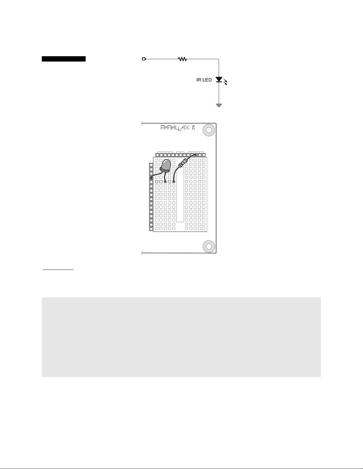
Figure 12
Blinking LED circuit.
P12
P15
P14
P13
P12
P11
P10
P9
P8
P7
P6
P5
P4
P3
P2
P1
P0
(916) 624-8333
www.parallaxinc.com
www.stampsinclass.com
Vdd VssVin
X3
X4
220
Ω
Vss
Rev A
© 2002
Code Listing
The simplest way to control a BASIC Stamp output pin is with the
HIGH (on) and LOW (off) commands. Both
commands require a pin number parameter. Let's take a look at Listing 1a to see HIGH and LOW in action.
' {$STAMP BS2}
' Program: LED Blink.BS2
' Purpose: Blinks an LED connected to BASIC Stamp pin P15
' ---------------------------------------------------------------
Start:
HIGH 15 ' turn LED on
PAUSE 500 ' wait one-half second
LOW 15 ' turn LED off
PAUSE 500 ' wait one-half second
GOTO Start ' do it again
As you can see, the program starts by making pin 15 go high (5 volts). This will cause the LED to light. In order
for us to see it, though, we must insert some time before we turn it back off. We can create a short program
delay with the
that follows is the delay time in milliseconds (
PAUSE command. Like HIGH and LOW, PAUSE requires a value parameter. For PAUSE, the value
1
/
second). In our program a PAUSE value of 500 will allow the
1000
LED to stay lit for one-half second.
Parallax, Inc. • BASIC Stamp HomeWork Board ver 1.1 Page 14
Page 15

Next, we make the LED control pin go to zero volts with LOW. With zero volts on both sides of the LED, no
current can flow and it turns off. Again, we use
PAUSE to create a delay so that we can actually see that it is off.
Finally, we start the process over by jumping to the line labeled Start with the GOTO command.
Download and run the program – you should see the LED blink happily on and off. If you don't, double-check
your connections; especially the orientation of the LED. If it doesn't blink you may have it in backward.
Now, as exciting as that was, we can do more and write "better" code. Better code is code that not only works,
but is easy for us and others to understand. Let's improve our little program just a bit. Take a look at Listing 1b.
' {$STAMP BS2}
' Program: LED Blink.BS2 (Version B)
' Purpose: Blinks an LED connected to the BASIC Stamp
' ---------------------------------------------------------------
LedPin CON 15 ' LED control pin
' ---------------------------------------------------------------
Start:
HIGH LedPin ' turn LED on
PAUSE 500 ' wait one-half second
LOW LedPin ' turn LED off
PAUSE 500 ' wait one-half second
GOTO Start ' do it again
In this version we introduce constant (CON) values. Constants give us a way to assign a useful name to a value
that doesn't change. There a couple of good reasons for using constants in our program:
1. If we need to change the pin that controls the LED, we only have to change one place in the program.
Using constants prevents program errors by not catching all the changes required when circuit
connections are modified.
2. By using a constant, we now have more of an idea of what is being controlled.
HIGH 15 could be
controlling anything; a light, a bell, a heater. We're forced to explain the process of our program in
comments. By using the constant name
LedPin, others reading our code know what is being controlled
and we can spend less energy explaining with comments.
Okay, so I'll bet you're wondering just how constants work.. They're actually used by the editor when the program
is being compiled to run on the BASIC Stamp. At the beginning of the compilation process the editor will replace
all the appearances of a constant name with its defined value. In our program,
HIGH 15 and the program will work just as in our first version. And don't worry, this replacement is an internal
HIGH LedPin will be replaced with
process used by the compiler – our source code listing will not be changed.
Give it a try. You'll see that the program runs exactly the same as it did the first time. This time, though, our listing
makes a bit more sense. Ready for more?
One of the things that makes
HIGH and LOW easy is that each command actually does two operations – that's
right, two. You see, to control a Stamp output pin we have to deal with two internal registers. The first is called
Dirs. The Dirs register is 16 bits wide; one bit for each I/O pin. When a bit in the Dirs register is zero (default at
start-up), the associated I/O pin will be an input. When we make a
Dirs bit a one, the associated I/O pin will be an
output.
The other register that we need to concern ourselves with is called
case, the bits in
Outs are connected to the I/O pins when the associated Dirs bits are set to one. When a bit in
Outs. Like Dirs, Outs is 16 bits wide. In this
Parallax, Inc. • BASIC Stamp HomeWork Board ver 1.1 Page 15
Page 16

Outs
is a zero, the associated output pin will be low (0 volts). When a bit in Outs is one, the associated output pin
will be high (5 volts).
So,
HIGH 15 is the same as:
Dir15 = 1
Out15 = 1
LOW 15 is the same as:
and
Dir15 = 1
Out15 = 0
You'll remember from the variables overview in Chapter XX that Dirs and Outs can be accessed as a Word (16
bits), as two Bytes (8 bits), as four Nibbles (4 bits) or as 16 individual Bits. So,
Dir15 corresponds to bit 15 of the
Dirs register.
The advantage of going to this depth is that we can gain more flexibility and control over our programs –
especially in terms of readability (this aspect will become much more important as our programs grow). Take a
look at Listing 1c. Notice how we really don't need any comments to explain what's going on? Pretty cool, huh?
' {$STAMP BS2}
' Program: LED Blink.BS2 (Version C)
' Purpose: Blinks an LED connected to the BASIC Stamp
' ---------------------------------------------------------------
LedPin VAR Out15 ' LED on/off control
LedCtrl VAR Dir15 ' LED i/o pin control
On CON 1
Off CON 0
' ---------------------------------------------------------------
Initialize:
LedCtrl = %1 ' make LED pin an output
Start:
LedPin = On
PAUSE 500
LedPin = Off
PAUSE 500
GOTO Start
Parallax, Inc. • BASIC Stamp HomeWork Board ver 1.1 Page 16
Page 17

Advanced LED Control
Another advantage to this program style is that we can cause the LED to follow the operation of a different value
within our program. We can do this because
Out15 is actually a bit-sized variable [a value that can change]. We
can copy another bit-sized variable to it and cause the LED to follow the value of that variable.
Listing 1d is a bit advanced, but you can handle it. Take a look and then we'll go into all the details.
' {$STAMP BS2}
' Program: LED Blink.BS2 (Version D)
' Purpose: Blinks an LED connected to the BASIC Stamp (advanced)
' ---------------------------------------------------------------
LedPin VAR Out15 ' LED on/off control
LedCtrl VAR Dir15 ' LED i/o pin control
blinkVal VAR Byte ' blink control value
blinkBit VAR Nib ' blink control bit
' ---------------------------------------------------------------
Initialize:
LedCtrl = %1 ' make LED pin an output
Start:
DEBUG CLS
FOR blinkBit = 0 TO 7 ' test all bits
FOR blinkVal = 0 TO 255 ' test all values
' report
DEBUG Home
DEBUG "Blink Value = ", DEC blinkVal, " ", CR
DEBUG "Blink Bit = ", DEC blinkBit, CR
DEBUG CR
DEBUG "Blink Value = ", BIN8 blinkVal, CR
DEBUG "Blink Bit = ", REP " "\(7 - blinkBit), "^ "
' control the LED
LedPin = blinkVal.LowBit(blinkBit)
PAUSE 5
NEXT
NEXT
GOTO Start
In this program we'll need a couple variables. The first is called blinkVal and it is defined as a Byte (8 bits). You'll
remember that a Byte can hold values from zero to 255. The other variable is called
Nib (4 bits). Being a Nib,
blinkBit to point at a bit in blinkVal and the LED will follow that bit value. It will be on when the bit is a one; off when
blinkBit can hold values from 0 to 15, but we only need it to go up to seven. We will use
blinkBit and is defined as a
the bit is a zero.
The main part of the program starts by opening the
DEBUG statement allows the BASIC Stamp send messages to the PC. This will let us know what's going on
DEBUG window and clearing it with CLS (clear screen). The
inside our program as it's running.
The bulk of the code is two
blinkBit and will run eight times (0 to 7). For each iteration of blinkBit, the inner loop, controlled by blinkVal will run
FOR-NEXT loops; one nested inside the other. The outside loop is controlled by
256 times (0 to 255). This is where the action takes place.
Parallax, Inc. • BASIC Stamp HomeWork Board ver 1.1 Page 17
Page 18

The first thing we'll do is create a report on what's happening. We start with DEBUG Home which causes the
DEBUG cursor [not visible] to move to the first row, first column of the screen. Next we'll print out the values of
blinkVal and blinkBit using the DEC modifier to specify their display as decimal numbers. If we leave DEC out, the
DEBUG window with attempt to display the characters defined by their current value – that's not what we want.
Then we'll print
blinkVal again, this time using the BIN modifier so that we see it as a binary value. Now we can
see what's going on inside of blinkVal. As its value changes we'll be able to see the corresponding bits change.
Finally, we'll use the value of blinkBit to position a pointer under the current blinkVal bit that is controlling the LED.
This line of code uses the
REP modifier to repeat a character. In our case we going to repeat a space. We
position it under the proper bit by subtracting the current blinkBit value from seven. When blinkBit is zero, this line
will print seven spaces, then the pointer. When blinkBit is one, it will print six spaces then the pointer. You get the
idea.
Now that we know what's going on, let's make it happen. The line of code that actually controls the LED uses
another advanced feature of the PBASIC language: variable modifiers. In this program we're using
LowBit.
Without an index (the value in parenthesis), LowBit will always point to bit zero of a variable. Since we want to
point at all bits, starting with zero and ending with seven, we will use the index. The index value is and offset into
the variable from bit zero. So,
LowBit(0) points to bit zero, LowBit(1) points to bit one and so on.
And, finally, there is a very short
PAUSE so we can see the LED blink when we’re on the low bits. In actuality,
sending the report to the DEBUG screen takes some time as well and contributes to the overall loop timing.
Wow, that was quite and interesting program for simply blinking an LED, wasn't it. If you're still not quite sure how
it works, don't worry, it will set in with time and we will review these techniques in other projects.
Test Your Knowledge
If the forward voltage of the LED is 1.7 volts, what is the current through the LED with the total series resistance
of 440 ohms (220 + 220)?
Parallax, Inc. • BASIC Stamp HomeWork Board ver 1.1 Page 18
 Loading...