

Page 1
Web Site: www.parallax.com
Forums: forums.parallax.com
Sales: sales@paral la x.c om
Technical: support@parallax.com
Office: (916) 624-8333
Fax: (916) 624-8003
Sales: (888) 512-1024
Tech Support: (888) 997-8267
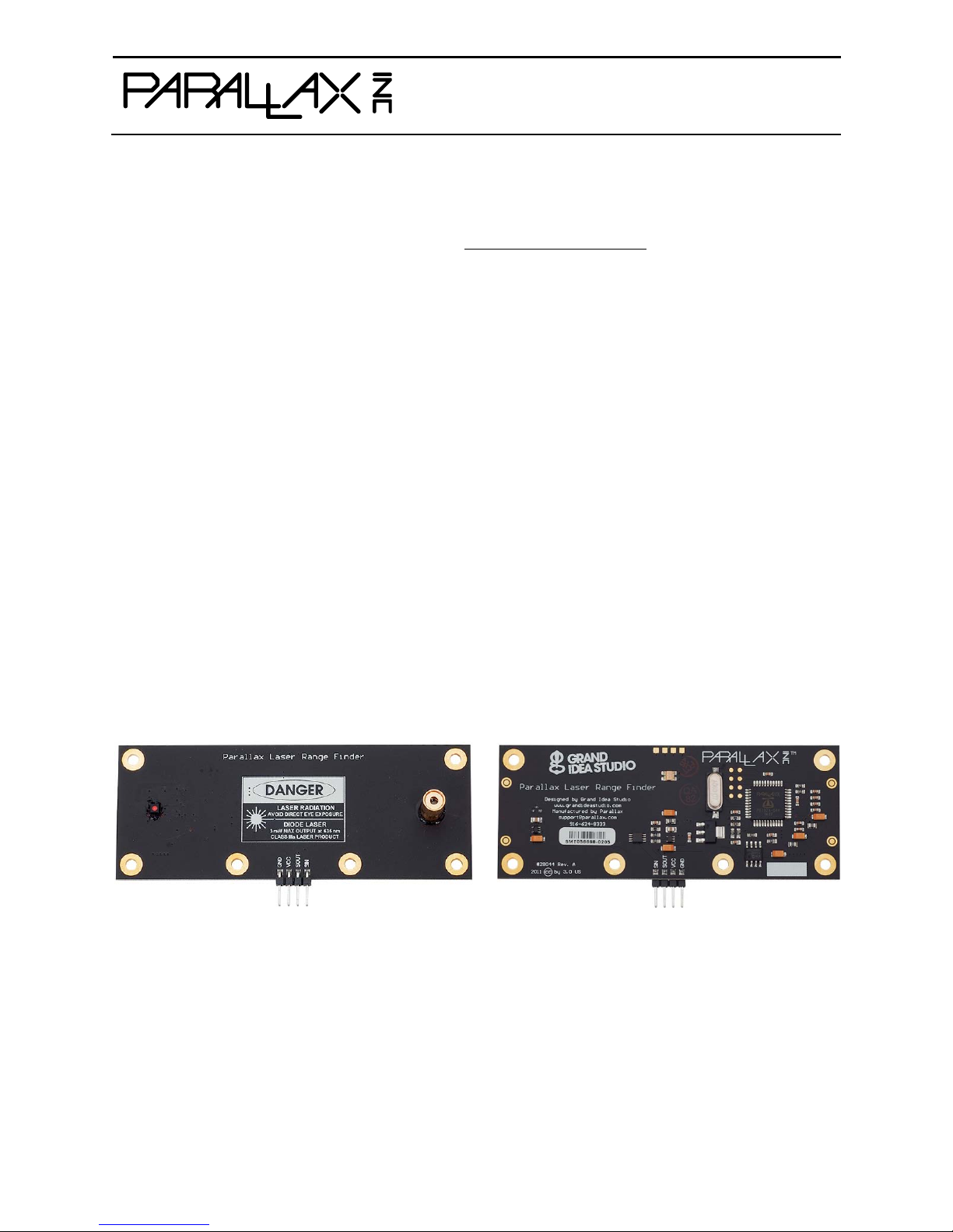
Parallax Laser Range Fi nd er (#28044)
Designed in co njunction with Grand Idea St udio (www.grandideastudio.com), the Parallax Laser Range
Finder (LRF) Module is a distance-measuring instrument that uses laser technology to calculate the
distance to a targeted object. The design uses a multicore Propeller microcontroller, CMOS camera, and
laser diode to create a low-cost laser range finder. Distance to a targeted object is calculated by optical
triangulation using simple trigonometry between the centroid of laser light, camera, and object.
Features
Optimal measurement range of 6–48
inches (15–122 c m) with an accuracy
error <5%, average 3%
Maximum object detection distance of
~8 feet (2.54 meters)
Range finding sample rate of 5 Hz
Key Specifications
Power requirements: 5 VDC @ 150 mA
Communication: Asynchronous serial
300–115,200 baud with automatic baud
rate detection
Operating temperature: 32 to 122 °F
(0 to 50 °C)
Compact module with integrated CMOS
camera and laser diode
Single row, 4-pin, 0.1” header for easy
connection to a host system
All engineering materials released as
open source under a Creative Commons
license; see page 23
Table of Contents
Connections .................................................... 2
Usage ............................................................ 2
Command Set ................................................. 3
Range and Accuracy ...................................... 10
Error Modes .................................................. 10
Electrical Characteristics ................................ 11
LRF Image Viewer ......................................... 12
Dimensions: 3.95" W x 1.55" H x 0.67" D
(10.05 W x 3.95 H x 1.7 D cm)
Application Ideas
Distance or liquid level measurements
Object detection and/or avoidance
Item counting
Hardware Design .......................................... 15
Theory of Operation ...................................... 16
Camera Interface .......................................... 19
Care and Handling ........................................ 22
Safety .......................................................... 22
Open Source Files and Example Code ............. 23
Revision History ............................................ 23
Copyright © Parallax Inc. Parallax Laser Range Finder (#28044) v2.0 10/31/2015 Page 1 of 23
Page 2
Pin
Name
Type
Function
1
GND
G
System ground. Connect to power supply’s ground (GND) terminal.
2
VCC
P
System power. 5 VDC input.
3
SOUT
O
Serial output to host. 5 V TTL-level interface, non-inverted, 8 data bits, no
parity, 1 stop bit, baud rate matched to host.
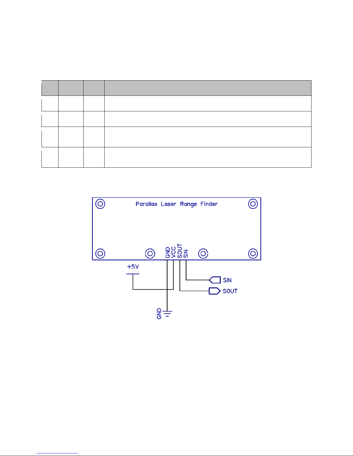
Connections
The LRF Module i nterfaces to any hos t microcontroller or computer system usi ng only four connect ions
(GND, VCC, SOUT, SIN).
4 SIN I Serial input from host. 3.3 V to 5 V TTL-level interface, non-inverted, 8 data
bits, no parity, 1 stop bit, baud rate matched to host.
Type: I = Inpu t, O = Output, P = Power, G = Ground
Use the following example circuit for connecting the Parallax Laser Range Finder Module:
Usage
The LRF Module is controlled by the host via a serial communications interface. To use, simpl y align the
LRF Module towards the target object and send the desired command.
The serial interface is configured for 8 data bits, no parity, 1 stop bit (8N1). Automatic baud rate
detection occurs on initial power-up of the LRF Mod ule. The Module wait s for a “U” character to be sent
by the host and will se t its baud rate t o match that of the host . Supported ba ud rates include 3 00, 600,
1200, 2400, 4800, 9600, 19200, 38400, 57600, and 115200.
When the LRF is ready to receive commands, it will send a “:” to the host. The LRF wait s in an idle state
until it receives a valid command, at which time it performs the command and returns command-specific
data (if any). The LRF will return a “?” u pon receiving an invalid command.
Copyright © Parallax Inc. Parallax Laser Range Finder (#28044) v2.0 10/31/2015 Page 2 of 23
Page 3

The camera system used in the LRF Module has automatic white balance, automatic exposure, and
automatic gain control enabled by default, and will automatically adjust its image to account for sud den
changes in lighting con diti ons. How ever , the LR F work s best i n a controlle d en vironm ent, s uch as i ndoors
with minimal changes in brightness across the frame. The LRF is also less reliable when the laser is
shining onto a bright object (for example, a white piece of paper), since the background subtraction
performed during image processing could potentially “subtract” the bright laser from the already bright
frame.
Status Indicator
A visual indication of the LRF Module’s operating state is given with the on-board LED (Light-Emitting
Diode). The LED is l ocated on the ba ck side of the LRF nea r the center of the board. The LED denotes
four states of the LRF:
1. Green: Idle state. Waiting for a command to be sent by the host.
2. Red: Active s tate . For ex ample, p erformi ng a rang e calcula tion or capturi ng an i mage wit h the
camera.
3. Orange (Solid): Baud rate detection state. The LRF is waiting for a “U” character to be sent by
the host in order to a utomatically set the communi cations baud rate . Occurs on LRF power-up
only.
4. Orange (Blinking): Error sta te. The LRF has malfunctioned. A message ident ifying the failed
operation will be transmitted on the SOUT (Serial Out) pin. See Error Modes, page 10, for details.
If the LED is OFF, the LRF may not be receiving power.
Command Set
All commands are single-byte, ASCII p rintable values and are not case-sensitive (upper case and lower
case will both work). No carriage return (CR) or linefeed (LF) is required after the command byte is sent.
Depending on the command, data may be returned by the LRF.
The command descriptions in this section are for LRF firmwa re version 2.0. For command descriptions of
earlier firmware versions, refer to product manual version 1.1. Examples are shown for direct connection
to a microcontroller (BASIC Stamp 2) and/or to a host PC via a terminal program.
Basic Commands
R
B
L
E
S
T
V
H
Single range measurement (returns a 4-digit ASCII value in millimeters)
Single range measurement (returns a 2-byte binary value in millimeters)
Repeated range measurement (any subsequent byte will stop the loop)
Adjust camera for current lighting conditions
Reset camera to initial settings
Toggle laser on/off
Display ver si on inf or mation
Display available commands
Copyright © Parallax Inc. Parallax Laser Range Finder (#28044) v2.0 10/31/2015 Page 3 of 23
Page 4

Capture & send processed frame (320x16, 8 bits/pixel grayscale) w/ background
subtraction
Advanced Commands
O
X
A
G
C
Display coordinate, mass, and centroid information for all detected blobs
Calibrate camera system for range finding
Adjust blob detection parameters
Capture & send single frame (160x128, 8 bits/pixel grayscale)
Capture & send single frame (320x16, 8 bits/pixel grayscale) w/ laser enabled
P
Command Details
R: Single range measurement (ASCII)
Takes a single range finding measurement and returns the distance to the target object as a printable
ASCII string (“D = ”) with a
4-digit decimal
milliseconds to complete.
The LRF Module is most accurate within its optimal measurement range of 6–48 inches (15–122 cm ). In
ideal conditions, a distance measurement of up to ~8 feet (2.54 meters) may be possible. While the
accuracy will be hindered at distances outside o f the optimal range, the LRF co uld still be used for gross
distance measurements or simple object detection. See Range and Accuracy, page 10, for details.
Terminal Example:
:R
D = 0288 mm
:
BS2 Example:
SEROUT LRF_TX, LrfBaud, ["R"] ' Send command
' Wait for distance measurement and store it as a decimal value
SERIN LRF_RX, LrfBaud, 3000, No_Response, [WAIT("D = "), DEC4 range]
B: Single range measurement (binary)
Takes a single range finding measurement and returns the distance to the target object as a
value in millimeters. Data is sent MSB first. A range measurement takes ~200 milliseconds to
binary
complete.
The LRF Module is most accurate within its optimal measurement range of 6–48 inches (15–122 cm ). In
ideal conditions, a distance measurement of up to ~8 feet (2.54 meters) may be possible. While the
accuracy will be hindered at distances outside o f the optimal range, the LRF co uld still be used for gross
distance measurements or simple object detection. See Range and Accuracy, page 10, for details.
Terminal Example:
:B
<binary data>
:
BS2 Example:
SEROUT LRF_TX, LrfBaud, ["B"] ' Send command
SERIN LRF_RX, LrfBaud, 3000, No_Response, [range.HIGHBYTE, range.LOWBYTE]
value in millimeters. A range measurement takes ~200
2-byte
Copyright © Parallax Inc. Parallax Laser Range Finder (#28044) v2.0 10/31/2015 Page 4 of 23
Page 5

L: Repeated range measurement
Continuously calls t he Sing l e rang e m ea sure me nt ( ASCII) command (“R”). O nce the loop has starte d, a ny
subsequent byte sent to the LRF Module will stop the command. Each range measurement takes ~200
milliseconds to complete.
Terminal Example:
:L
D = 0288 mm
D = 0289 mm
D = 0289 mm
D = 0289 mm
<any key pressed>
:
E: Adjust camera for current lighting conditions
Calibrates the LRF Module’s camera for the current lighting conditions. This may aid the camera in
successfully detecting the laser spot within the frame, which increases accuracy of the range finding
functionality.
The command first e nsures that a utomatic white balance (AWB), automatic exposure control (AEC), and
automatic gain control (AGC) are enabled. Then, after a 10 second delay for the camera image to settle,
AWB, AEC, and AGC are disabled. The EV/exposure level is also reduced to a minimum value. This will
cause the entire camera frame, including any previously bright areas, to appea r dark. A bright laser spot
may now be more easily identifiable within the frame.
The camera’s settings can be reset to their default with the “S” command.
Terminal Example:
:E
<short delay>
:
BS2 Example:
SEROUT LRF_TX, LrfBaud, ["E"]
SERIN LRF_RX, LrfBaud, [WAIT(":")]
S: Reset camera to initial settings
Resets and initializes the LRF Module’s camera to its default, power-up configur ation, including e nabling
automatic white balance (AWB), automatic exposure control (AEC), and automatic gain control (AGC). It
may take up to 10 seconds for the camera image to settle after the command is sent.
This command is particularly helpful when the “E” command has been used to adjust the camera for
current lighting cond itions and the user wishes to reset the camera settings w ithout power cycling the
LRF Module.
Terminal Example:
:S
:
BS2 Example:
SEROUT LRF_TX, LrfBaud, ["S"]
SERIN LRF_RX, LrfBaud, [WAIT(":")]
Copyright © Parallax Inc. Parallax Laser Range Finder (#28044) v2.0 10/31/2015 Page 5 of 23
Page 6

T: Toggle laser on/off
Allows for manual control of the laser diode. The command will toggle the laser diode on and off.
Commands that make use of the laser diode (“R”, “B”, “L”, “O”, “X”, “C”, and “P”) will supersede the state
set using this command.
Terminal Example:
:T
<laser diode on>
:T
<laser diode off>
:
BS2 Example:
SEROUT LRF_TX, LrfBaud, ["T"] ' Turn laser diode on
SERIN LRF_RX, LrfBaud, [WAIT(":")]
SEROUT LRF_TX, LrfBaud, ["T"] ' Turn laser diode off
SERIN LRF_RX, LrfBaud, [WAIT(":")]
V: Display version information
Lists version and calibration information for the LRF Module. This data is useful for troubleshooting and
debugging.
FW: Firmware revision (major.minor)
MFG and PID: Manufacturer ID and Product ID of the LRF’s on-board camera
SLOPE, INTERCEPT, PFC_MIN: Device-specific values calculated during the calibration process
(“X”) and used for range finding (if the LRF Module is uncalibrated, the values will all be
0xFFFFFFFF)
LOWER_BOUND , UPPER_BOUND, BLOB_MASS_THRESHOLD: Parameters used for blob detection
during the range finding process. The values default to those shown in the example output
below, but can be changed using the “A” command.
Terminal Example:
:V
Parallax Laser Range Finder
Designed by Grand Idea Studio [www.grandideastudio.com]
Manufactured and distributed by Parallax [support@parallax.com]
FW = 2.0
MFG = 7FA2
PID = 7691
SLOPE = +0.001418615 (3AB9F0CE)
INT = -0.009308979 (BC1884B0)
PFC_MIN = 28
LOWER_BOUND = 50
UPPER_BOUND = 255
BLOB_MASS_THRESHOLD = 16
:
Copyright © Parallax Inc. Parallax Laser Range Finder (#28044) v2.0 10/31/2015 Page 6 of 23
Page 7

H: Display available commands
Lists all available commands that the LRF Module supports.
Terminal Example:
:H
Basic Commands:
R Single range measurement
B Single range measurement (binary response, 2 bytes)
L Repeated range measurement (any subsequent byte will stop the loop)
<more commands listed, but not shown in this manual>
:
O: Display coordinate, mass, and centroid information for all detected blobs
Displays coordinate, mass, and centroid (center of m ass) information for up to 6 detected blobs within
the camera’s field-of-view. This information can be used for custom im age proce ssing or ob ject dete ction
outside of the sta ndard LRF Module functio nality. The blob detection begins on the left side of the frame
and “scans” to the right. See Image Pr ocessing a nd Blob Detection, page 20, for details.
L: X coordinate of the beginning (left side) of the detected blob
R: X coordinate of the end (right side) of the detected blob
M: Mass of blob (sum of all valid pixels within the blob)
C: Centroid (center of mass) of blob
<: Marker to indicate if the blob is less than the BLOB_MASS_THRESHOLD
*: Marker to indicate the blob with the largest m ass (primary blob)
In many cases, if a single blob is detected within the frame, it is likely t he laser spot. In other cases,
there may be reflections of the laser light or other spots that are not related to the laser. Generally, the
blob with the largest mass within the frame can be c onsidered the actual laser spot.
Terminal Example:
:O
0: L = 81 R = 88 M = 14 C = 84 <
1: L = 137 R = 232 M = 917 C = 181 *
2: L = 235 R = 254 M = 170 C = 244
:
X: Calibrate camera system for range finding
To account for manufacturing and assembly variances, particularly related to the camera and laser diode
alignments, each LR F Module must be ca librated. This occ urs during producti on, but the LRF ca n be recalibrated by the user at a later date if desired. If a new major version of firmware is loaded (for
example, upgrading from firmware version 1.0 to 2.0), the LRF will need to be re-calibrated.
The calibration routine requires the user to place the LRF Module at 6 fixed distances (from 20 cm to 70
cm at 10 cm intervals), measured from the front face of the LRF circuit board. The LRF takes
measurements at each distance a nd calculates the SLOPE, INTERC EPT, and PFC_MI N values. The va lues
are then stored in an unused portion of the non-volatile boot Serial EEPROM. They will remain intact
during a power cycle .
Copyright © Parallax Inc. Parallax Laser Range Finder (#28044) v2.0 10/31/2015 Page 7 of 23
Page 8

The SLOPE and INTERCEPT are used to convert the pixel offset to an angle using a best-fit slopeintercept linear equation. The PFC_MIN value is used to set the maximum a llowable distance of the LRF
Module, which is represented by a minimum pixels from center value. See Optical Triangulation, page 17,
for details.
The LOWER_BOUND, UPPER_BOUND, and BLOB_MASS_THRESHOLD parameters, used for blob detection
during range finding, are reset to their default values during this process (50, 255, and 16, respectively).
A video demonstrating the calibration process can be found on YouTube:
www.youtube.com/watch?v=1gk_tRbJO84
Terminal Example:
:X
Are you sure you want to calibrate (Y/N)?Y
Set LRF to D = 20 cm and press spacebar (any other key to abort)
pfc: 289 angle: 0.3718561
pfc: 289 angle: 0.3718561
pfc: 290 angle: 0.3718561
pfc: 289 angle: 0.3718561
< more steps listed, but not shown in this manual >
Set LRF to D = 70 cm and press spacebar (any other key to abort)
pfc: 105 angle: 0.1109708
pfc: 105 angle: 0.1109708
pfc: 105 angle: 0.1109708
pfc: 105 angle: 0.1109708
SLOPE = +0.001420366 (3ABA2B96)
INT = -0.03679396 (BD16B544)
PFC_MIN = 48
LOWER_BOUND = 50
UPPER_BOUND = 255
BLOB_MASS_THRESHOLD = 16
Write new values (Y/N)?Y
:
A: Adjust blob detection parameters
Receive new blob detection parameters from the user a nd store them in memory. The current value is
displayed within the square brackets ([]). Each parameter can have a value from 0 to 255 and must be
followed by a carriage return (CR). If the entered value is out of range, an error message will be
displayed and the comma nd w ill abort. W hen all parameters have been properly entered, they are stored
in an unused portion of the non-volatile boot Serial EEPROM. They will remain intact during a power
cycle.
LOWER_BOUND is the minimum brightness value and UPPER_BOUND is the m aximum brightness value
used during the thresholding phase of blob detection. If a pixel within the processed frame is greater
than or equal to LOWER_BOUND (default of 50) and less than or equal to UPPER_BOUND (default of
255), it is set to ‘1’ (white) and included in the column sum. Otherwise, it is set to ‘0’ (black).
BLOB_MASS_THRE SHOLD is the minimum blob m ass (the number of valid ‘1’ pixels within the total blob)
required for the blob to be considered as the primary blob. If the blob mass is greater t han or equal to
BLOB_MASS_THRESHOLD (default 16), it is included. This parameter reduces the chance of using an
unlikely blob (such as one ca used by optical noise or reflection) for range finding calculations.
See Image Processing and Blob Detection, page 20, for details.
Copyright © Parallax Inc. Parallax Laser Range Finder (#28044) v2.0 10/31/2015 Page 8 of 23
Page 9

Terminal Example:
:A
Enter new LOWER_BOUND [50]: 40
Enter new UPPER_BOUND [255]: 200
Enter new BLOB_MASS_THRESHOLD [16]: 30
:
G: Capture & send single frame (160x128, 8 bits/pixel grayscale)
Capture a 160x128 re solution grayscale image with the LRF Module’s camera and return the data in a
binary format.
The data is sent MSB first, one byte per pixel, starting at the upper-left pixel location (0,0), moving left to
right, top to bottom across the fram e, and ending at the lower-ri ght pixel locat ion (160,128). E ach byte
corresponds to the brightness value of a single pixel where 0x00 is black and 0xFF is white.
A total of 20,480 bytes of binary data is sent. An ASCII footer (“END”) is attached to the end of the
binary data stream to assist in identifying the end of the frame.
This command can be used from within the LRF Image Viewer tool to easily view the image.
Terminal Example:
:G
<binary data>END
:
C: Capture & send single frame (320x16, 8 bits/pixel grayscale) w/ laser enabled
Capture a 320x16 resolution grayscale image with the LRF Module’s camera and return the data in a
binary format. The laser diode is enabled during the frame grab for testing and alignment purposes.
The data is sent MSB first, one byte per pixel, starting at the upper-left pixel location (0,0), moving left to
right, top to bottom across the frame , and ending at the lower-right pixel locat ion (320,16). Each byte
corresponds to the brightness value of a single pixel where 0x00 is black and 0xFF is white.
A total of 5,120 bytes of binary data is sent. An ASCII footer (“END”) is a tta ched to the end of the b inary
data stream to assist in identifying the end of frame.
This command can be used from within the LRF Image Viewer tool to easily view the image.
Terminal Example:
:C
<binary data>END
:
P: Capture & send processed frame (320x16, 8 bits/pixel grayscale)
Capture a 320x16 resol ution processed im age with the LRF Module’s ca mera and return the data in a
binary format. This mode is specific for range finding functionality and consists of a “background
subtracted” image where one frame is taken with the laser diode off, one frame taken with the laser
diode on, and the data of the two frames subtracted. This helps to isolate the laser spot within the frame.
See Image Processing and Blob Detection, page 20, for more details.
The data is sent MSB first, one byte per pixel, starting at the upper-left pixel loca tion (0, 0), movi ng left to
right, top to bottom across the frame , and ending at the lower-right pixel locat ion (320,16). Each byte
corresponds to the brightness value of a single pixel where 0x00 is black and 0xFF is white.
Copyright © Parallax Inc. Parallax Laser Range Finder (#28044) v2.0 10/31/2015 Page 9 of 23
Page 10

A total of 5,120 bytes of binary data is sent. An ASCII footer (“END”) is attached to the end of the binary
data stream to assist in identifying the end of frame.
This command can be used from within the LRF Image Viewer tool to easily view the image.
Terminal Example:
:P
<binary data>END
:
Range and Accurac y
The LRF Module is most accurate within its optimal measurement range of 6–48 inches (15–122 cm).
Within this range, error can span from zero (no difference between actual distance and the distance
calculated by the LRF) to 5%. On average, the error is approximately 3%.
Within the optimal measurement range, the horizontal position of the laser spot within the camera’s
frame (which is used to determine distance to the target object) changes noticeably. At longer distances,
although the camera can still “see” the laser spot, the horizontal position does not change as much,
causing a significant reduction in accuracy. Ac curacy also varies with lighting conditions and mate rial of
the target object, which affect the LRF Module’s capability to determine the laser spot within the camera’s
frame.
The LRF Module intentionally limits the maximum detectable distance to 100 inches (254 cm). At
distances less than 6 inches, the lase r spot is out of the camera’s field-of-view, so no range calculat ion
can occur. See Optical Triangulation , page 17, for more details.
The following chart shows example measurements taken with a LRF Module. The Calculated Distance,
Difference (Δ), and % Error will vary slightly per unit.
Error Modes
In the event that the LRF enters the e rror state (sig nified by a blinki ng orange LE D status indicat or), an
ASCII message identifying the failed operation will be transmitted on the SOUT (Serial Out) pin.
Messages include:
ERR: cam.start. Error initializing the camera on LRF power-up. This may be caused by a
communication error between the Propeller and camera.
ERR: cam.init. Error performing the “S” command (Reset camera to initial settings). This may
be caused by a communication error between the Propeller and camera.
Copyright © Parallax Inc. Parallax Laser Range Finder (#28044) v2.0 10/31/2015 Page 10 of 23
Page 11

Supply Voltage
Supply Current, Idle
Supply Current, Active
Condition
Value
Operating Temperature
0 ºC to +50 ºC (+32 ºF to +122 ºF)
Storage Temperature
-40 ºC to +125 ºC (-40 ºF to +257 ºF)
Supply Voltage (VCC)
+4.5 V to +5.5 V
Ground Voltage (VSS)
0 V
Voltage on any pin with respect to V
SS
-0.3 V to +7.0 V
ERR: cam.calibrate. Error performing the “E” command (Adjust camera for current lighting
conditions). This may be caused by a communication error between the Propeller and camera.
ERR: cam.setRes. Error setting the camera’s resolution. This may be caused by a
communication error between the Propeller and camera.
ERR: cam.getID. Error retrieving the camera’s manufacturer and product IDs. This may be
caused by a communication error between the Propeller and camera.
ERR: eeprom.ReadLong. Error reading calibration data from the external Serial EEPROM. This
may be caused by a communication error between the Propeller and EEPROM or an incorrect
type of EEPROM device.
ERR: eeprom.WriteLong. Error writing calibration data to the external Serial EEPROM. This
may be caused by a communication error between the Propeller and EEPROM or an incorrect
type of EEPROM device.
If the LRF is in an error state, but no error message is transmitted, then there is likely a failure with
starting either the serial communication or auto baud detection cog.
For further assistance, please contact Parallax technical support.
Electrical Characteristics
At VCC = +5.0 V and TA = 25 ºC unless otherwise noted.
Parameter Symbol
VCC
I
IDLE
ICC
Min. Typical Max.
4.5 5.0 5.5
--- 82 ---
--- 126 150
Specification
Unit
V
mA
mA
Absolute Maximum Ratings
NOTICE: Stresses above those listed under “Absolute Maximum Ratings” may cause permanent damage
to the device. This is a stress rating only and functional ope ration of the device at those or any other
conditions above those indicated in the operatio n listings of this specification is not implied. Exposure to
maximum rating conditions for extended periods may affect device reliability.
Copyright © Parallax Inc. Parallax Laser Range Finder (#28044) v2.0 10/31/2015 Page 11 of 23
Page 12

LRF Image Viewer
The LRF Image Viewer is an easy-to-use, PC-based graphical interface that allows direct and simple
control of the LRF Module:
Send commands to the LRF
Read system/debug messages from the LRF
Capture/display/save images from the LRF’s cam era
Enable PC-side image processing functionality (blob detection and identifica tion, range/distance
calculations)
The LRF Image Viewer supports all versions of LRF Module firmware. Features vary slightly depending on
firmware version. The user interface will be configured automatically after s uccessful connection to t he
LRF Module (using the Con nect but ton). The descriptions in this section are for LRF firmware ver sion 2. 0.
For descriptions of earlier firmware versions, refer to the LRF Module product manual version 1.1.
The LRF Image Viewer application was designed in Microsoft Visual Basic .NET. It requires Microsoft’s
.NET Framework Version 2.0 Redistributable Package to be installed on the host PC:
http://download.cnet.com/Microsoft-NET-Framework-Redistributable-Package-x86/3000-10250_4-
10726028.html
The LRF Module co nne cts t o the host PC via its TTL-level serial i nterfa ce t hrough a USB -to-Serial adapter
(Parallax #280 24 or compatible). A demonstrat ion of an early release of the LRF Image Viewer can be
found on YouTube:
www.youtube.com/watch?v=iHvMl2scUdA
Copyright © Parallax Inc. Parallax Laser Range Finder (#28044) v2.0 10/31/2015 Page 12 of 23
Page 13

LRF Image Viewer Interface
The LRF Image Viewer has a variety of windows, controls, and features:
COM Port menu: Provide s a selection of COM ports available on the host PC (i ncludes any virtual ser ial
ports provided by common USB-to-Serial interfaces)
Baud Rate menu: Provides a list of supported baud rates (9600, 19200, 38400, 57600, and 115200).
Connect/Disconnect buttons: Opens/closes a serial connection on the specified COM port at the
selected baud rat e. After opening a serial connection w ith the Connect button, the LRF Image
Viewer will send the required “U” character to allow the LRF Module to automatically detect the
host PC’s baud rate.
System Messages wind ow: Displays operational or debug messages sent by the LRF Image Viewer
software.
Terminal Console wi ndow: Displays the data sent to and received from the L RF Module via its serial
interface.
Text Entry bo x: This yellow text box beneath the Terminal Console allows the user to type commands
and send them dire ctl y t o t he LRF Mod ule . T he t ext is only t rans mit te d w hen the Send button (or
Enter key) is pressed. Any data returned by the LRF will be displayed in the Terminal Console.
Image window: Displays an image captured by the LRF Module.
Grab Image button: Captures an image with the LRF Module’s camera and displa ys it in the Image
Window. The adjacent radio buttons are used to select one of three image types:
Full Frame: 160x128 resolution grayscale image, achieved b y sending a “G” command to the
LRF.
ROI: 320x16 resolution grayscale image, achieved by sending a “C” command to the LRF.
The laser diode is enabled during the frame grab for testing and alignment purposes.
ROI Processed: 320x16 resolution “processed” grayscale image, achieved by se nding a “P”
command to the LRF. The image is created by capturing one frame with the laser diode off,
another frame with the laser diode on, and then subtracting the data of the two frames. This
helps to isolate the laser spot within the frame, which is useful for range finding functio nality.
Save Image button : Saves the image currently displayed in the Image Window. The adjacent radio
buttons are used to select a file type of standard bitmap (.BMP) or raw binary (8 bits/pixel
grayscale, each byte corresponding to the bri ghtness value of a single pixel whe re 0x00 is black
and 0xFF is white).
Copyright © Parallax Inc. Parallax Laser Range Finder (#28044) v2.0 10/31/2015 Page 13 of 23
Page 14

Blob Detectio n and Range Finding functionality: Enables the LR F Image Viewer to use its internal
image processing and blob detection routines (instead of the functionality on-board the LRF
Module) to identify pixels within a captured frame and to calculate range/distance.
Upon successful connection of the LRF Module to the LRF Image Viewer (using the Connect
button), the control boxes are populated with values retrieved from the LRF Module.
The Blob Detectio n checkbox is only availabl e when the ROI Processed radio button is sele cted
(located next to the Grab Image button). When the checkbox is selected, the adjacent controls
become available.
The Upper and Lower controls are used to set the maximum and minimum brightness values,
respectively, that a pixel m ust fall between in order for it to be displayed and included for range
finding purposes. The corresponding shade of grey is displayed next to the controls. These
controls represent the UPPER_BO UND and LOWER_B OUND values on the LRF Module.
The Minimum Blob Mass control is the minimum blob mass required for the bl ob to be considered
as the primary blob. If the blob mass is greater than or equal to the value, it is includ ed. This
parameter red uces the chance o f using an unl ikely blob (s uch as one cau sed by optical noise or
reflection) for range finding calculations. This control represents the BLOB_MASS_THRESHOLD
value on the LRF Modul e.
The above 3 controls can be manually adjusted to help fine-tune the LRF Module for ideal
operation within a specific environment. Once the desired values are obtained, they can be
stored in the LRF Module using the “A” command.
The Centroid and B ounds ra dio buttons a re used to choose how to mark t he primar y blob if one
is detected. The Centroid selection draws a red vertical line through the centroid (center of mass)
of the blob. The Bounds selection draws re d vertical line s at t he be ginning and en d locations (le ft
and right) of the blob.
The Slope and Intercept text boxes show t he respective values used during the range finding
process. These values vary per module and calculated during calibration (“X”).
The Pixels from Center text box displays the number of pixels the primary blob is aw ay from the
center point of the frame. This value is used for range finding calculations.
The Range text boxes show the calculated distance to the target object in centimeters (top) and
inches (bottom).
Copyright © Parallax Inc. Parallax Laser Range Finder (#28044) v2.0 10/31/2015 Page 14 of 23
Page 15

Hardware Design
The LRF Module’s m ajor hardware components include:
Parallax Propeller P8X32A-Q44
OmniVision OVM7690 640x480 CMOS CameraCube
Arima APCD-635-02-C3-A Laser Diode
Assembly Drawing
All components are mounted on the back side of the board with the exception of the camera and laser
diode. The center points of the camera and laser diode are 78 mm apart.
On the back side of the LRF Module, the Propeller (U2), its supporting electronics, and the camera
interface circuitry are located on the right and the las er diode control cir cuitry is on the left. A dotted line
(not printed on the actua l LRF Module) indicates the recomme nded cutting point if the user wishes to
separate the laser diode control circuitry from the rest of the LRF for custom projects.
A Prop Plug (Parallax #32201) can attach to the four pads (JP2) on the back of the LRF in order to
reprogram the Propeller’s firmware using the Parallax Propeller Tool software. Calibra tion and parametr ic
data will remain intact provided the same major version of firmware is loaded. Otherwise, the LRF will
need to be re-calibrated using the “X” command (for example, if upgrading from firmware version 1.0 to
2.0).
Eight unused GPIO pins (P16-P23) are available via surface mount pads near the Propeller. The pins are
spaced to support a dual-row, 0.1” male header.
Copyright © Parallax Inc. Parallax Laser Range Finder (#28044) v2.0 10/31/2015 Page 15 of 23
Page 16

Theory of Operation
This section describes advanced details of the LRF Module operation.
Program Structure
As of LRF Module firmware version 2.0, the source tree consists of 5 custom obje cts and 7 ob jects e ither
included with the Parallax Propeller development environment or written by others and posted to the
Parallax Object Exchange (
their original to remove unused code and/or to meet needs specific to the LRF Module.
LRF_OVM7690.spin
│
├──LRF_con.spin
│
├──OVM7690_obj.spin
│ │
│ ├──LRF_con.spin
│ │
│ ├──OVM7690_fg.spin
│ │ │
│ │ └──LRF_con.spin
│ │
│ ├──OVM7690_fg_roi.spin
│ │ │
│ │ └──LRF_con.spin
│ │
│ ├──pasm_i2c_driver_Lite.spin
│ │
│ └──Synth.spin
│
├──JDCogSerial_Lite.spin
│
├──F32_Lite.spin
│
├──FloatString_Lite.spin
│ │
│ └──FloatMath_Lite.spin
│
└──Basic_I2C_Driver_Lite.spin
LRF_OVM7690.spin is the top object file. This object handles the user interface, command processing,
and laser range finding mathemati cs.
LRF_con.spin provides the global constants used thr oughout the program, including camera resolution,
blob detection, range finding, and calibration settings.
OVM7690_obj.spin provides the low-level communication interface for the OmniVision OVM7690 CMOS
CameraCube module.
OVM7690_fg.spin and OVM7690_fg_roi.spin are the frame grabber objects for 160x128 and 320x16
grayscale images, respectively. They retrieve data from the OVM7690 and store it in the hub RAM
frame buffer. OVM7690_fg_roi.spin also provides a subset of blob detection functionality. The
objects are written in Propeller Assembly (PASM) due to their complex timing requirements.
pasm_i2c_driver_Lite.spin pr ovides the I2C protocol inte rface for comm unication w ith the OVM769 0.
Written by Dave Hein.
http://obex.parallax.com). Objects with a _Lite prefix have been modified from
Copyright © Parallax Inc. Parallax Laser Range Finder (#28044) v2.0 10/31/2015 Page 16 of 23
Page 17

Synth.spin is a frequency synthesizer used to generate the clock signal required by the OVM7690.
Included with the Parallax Propeller Tool.
JDCogSerial_Lite.spin provides full-duplex serial communication. Written by Carl Jacobs.
F32_Lite.spin p rovides IEEE 754-complia nt 32-bit floating point math routines used for range finding
and calibration. Written by Jonathan “lonesock” Dummer.
FloatString_Lite.spin and FloatMath_Lite.spin provide IEEE 754-compliant 32-bit fl oating point-to-
ASCII string conversion routines. Included with the Parallax Propeller Tool.
Basic_I2C_Driver_Lite.spin provides the I2C protocol inter face for boot EEPROM comm unication. The
LRF Module has a 64KB boot EEPROM. Only the first 32KB is used by the Propeller for program
storage, so the remaining 32KB is available for data storage. Each LRF Module’s calibration values
and blob detection parameters are stored in the data area. Written by Michael Green.
Optical Triangulation
The LRF Module uses opti cal triangulation for range finding, where the distance to the target object is
calculated with simple trigonometry between the center points of laser light, camera, and object. The
design of the LRF Module is based, in theory, on the implementation of Todd Danko’s Webcam Based DIY
Laser Rangefinder (
https://sites.google.com/site/todddanko/home/webcam_laser_ranger).
Referring to the figure above, a laser diode module shines a laser spot onto the target object. The value
h is a fixed, known distance between the center points of the laser diode and the camera (78 mm for the
LRF Module). When the distance to the target object D changes, so do both the angle θ and the value pfc
(pixels from center), which is the number of pixels the centroid of the primary blob (laser spot ) is away
from the camera’s center point.
Copyright © Parallax Inc. Parallax Laser Range Finder (#28044) v2.0 10/31/2015 Page 17 of 23
Page 18

As the object gets closer, the value of pfc (and angle θ) increases. As the object gets farther away, pfc
(and angle θ) approaches zero. If the angle θ is known, then trigonometry can be used to calculate the
distance value D:
tan θ = h / D
Solving for D:
D = h / tan θ
Since the LRF M odule’s blob detection rout ine returns a pfc value, an intermediate step is requir ed to
correlate that value with an actual angle θ. The relationship between pfc and angle can be described with
a slope-intercept linear equation (
The following chart sho ws measurements ta ken with a LRF Module. pfc is on th e X-axis and angle is on
the Y-axis. The dark blue diamonds show the actual measurements and the resulting best-fit linear
equation is printe d on the chart and denoted with a light blue line:
www.math.com/school/subject2/lessons/S2U4L2GL.html).
Once the laser is shined onto the target object and the pfc value of the laser spot is received, an angle θ
can be calculated using the slope-intercept equation and passed to the trigonometric function to
determine the actual distance the range finder is from the target object.
To account for manufacturing and assembly variances, particularly related to the camera and laser diode
alignments, each LRF Module must be calibra ted using the “X” command. T his will determine the ideal
slope and intercept values for that particular module.
Copyright © Parallax Inc. Parallax Laser Range Finder (#28044) v2.0 10/31/2015 Page 18 of 23
Page 19
Camera Interface
The OmniVision OVM7690 640x480 CMOS CameraCube provides a digital interface:
DVP[7:0] (Digital vid eo port): 8-bit wide output bus correspo nding to pixel information sent
in the selected output format from the OVM7690 (RAW RGB, RGB565, CCIR656, or
YUV422/YCbCr422).
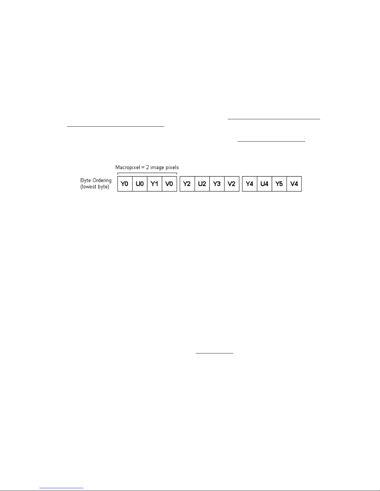
The LRF Module is configured for YUV422 output (
https://en.wikipedia.org/wiki/YCbCr). Y is the luma component - brightness in grayscale - and U
and V are chroma components - color differences of blue and red, respectively. The particular
format of YUV 422 used by the OVM7690 is known a s YUY2 (
each 16-bit pixel is given an 8-bit Y component and alternating 8-bit U or 8-bit V component:
Y0U0 corresponds to a single pixel start ing from the left, Y1V0 is the 2nd pixel, etc. Every pixel
has Y data, and U and V are every other pixel. T he LRF Module only uses the grayscale portion
(Y) of the output. The chroma components (U/V) are ignored.
VSYNC (Vertical sync): Indicates the beginning of a new fra me by pulsing hig h.
https://en.wikipedia.org/wiki/YUV and
www.fourcc.org/yuv.php), i n which
HREF (Horizon tal refer ence) : Indicates the start o f the next row of pixels b y pulsing high. By
keeping count of the num ber of HREF pulses received since the last VSYNC, we can determi ne
which horizontal line of the video fram e we are currently on.
PCLK (Pixel clock): Asserte d when valid pixel data is available on the DVP bus. For a 640 pixel
line in YUV422 format (16 bits/pixel), 10,240 pixel clock cycles will occur after each HREF pulse.
There are nearly one hundred 8-bit registers within the OVM7690 device that require configuration,
including, but not limited to, general settings, output format selection, resolution, frames per second,
automatic white balance, and gain control. Due to confidentiality concerns, OmniVision does not allow
explicit references or detailed explanations of camera configuration registers. Explanations of group
settings are allowed and provided wit hin the LRF Module source code to give the user an overview of
camera operation. To obtain full OVM7690 product specifications, a non-disclosure agreement (NDA)
must be executed with OmniVision Technologies, Inc. (
Frame Grabber
The frame grabber cogs (OVM7690_fg.spin and OV M7690_fg_roi.spin) onl y execute when started by a
calling object. They rece ive 160x128 and 32 0x16 grayscale images, respectively, and store them in the
frame buffer. OVM7690_fg_roi.spin also handles the background subtraction, pixel thresholding, and
column summing phases of blob detection (needed for the range finding process). The objects are
written in Propeller Assembly (PASM) due to their complex timing requirements.
www.ovt.com).
Copyright © Parallax Inc. Parallax Laser Range Finder (#28044) v2.0 10/31/2015 Page 19 of 23
Page 20

Grabbing a frame consists of waiting for VSYNC to go high, which signals the start of a new frame, and
then waiting for HRE F to g o high, whi ch signal s the st art of a ne w line. Then, pix el data (Y/luma only) is
captured from DVP[7:0] every time PCLK goes high and is stored in the frame buffer. After the complete
frame is stored in the buffer, the cog sets a flag in hub RAM to a non-zero st ate so the calling object
knows that the fram e grab is done. The cog then stops itself.
The frame grabber cogs support three modes:
1. Single Frame, 160x128: 8 bits/pixel grayscale image (in OVM7690_fg.spin).
2. Single Frame, 320x16: 8 bits/pixel grayscale image (in OVM7 690_fg_roi.spi n). The laser diode
is enabled during the frame grab for testing and alignment purposes.
3. Processed Frame, 320x16: 8 bits/pixe l processed grayscale i mage (in OVM7690_ fg_roi.spin).
This mode is specific for range fin ding functionality and consists of a “background subtracted”
image where one frame is taken with the laser diode off, one frame taken with the laser diode
on, and the data of the two frames subtracted. This helps to isolate the laser spot within the
frame. The frame grabber then handles the pixel thresholding and colum n summing phases of
blob detection. The results of the column summing are stored in an array in hub RAM.
Image Processing and Blob Detection
The primary function of the LRF Module is to capture an image with the camera and determine the
location of the laser spot (blob) within the frame. Once the blob is detected, its centroid (center of mass)
and resulting pfc value (pixels from center) are determined and passed to the r outine that cal culates t he
distance from the LRF to the target object.
The LRF Module’s image processing and blob detection functions as follows:
1. Background Subtract ion. Grab two consecutive frames—one with the laser diode off and o ne
with the laser di ode on. Each pixel’s Y/luma component from the first frame is subtracted from
the same pixel’s Y/luma component from the second frame (and absolute valued), leaving only
the pixels that have c hanged in brightnes s betwe en the two fr ames. All ot her ba ckground det ails
(anything that has stayed the same between the two frames) disappear. More information on
pixel/background subtraction can be found at:
http://homepages.inf.ed.ac.uk/rbf/HIPR2/pixsub.htm
2. Thresholding. Look at the grayscale value of each pixel in the processed frame (8 bits, where
0x00 is black and 0xFF is white) and determine if it i s within the defi ned bright ness bounds. I f a
pixel is greater than or equal to LOWER_BOUND (default of 50) and less than or equal to
UPPER_BOUND (default of 255), it is set to ‘1’ (white). Otherwise, it is set to ‘0’ (black):
3. Column Sum. Count t he number o f ‘1’ pixels wi thin each ve rtical colum n. This re sults in a one dimensional array co ntaining the number of “valid ” pixels per column. Summing the valid pixels
makes it easier to quickly search the frame to locate any blobs. The following i mage shows the
zoomed-in blob with the column’s sum printed at the bottom of each column:
Copyright © Parallax Inc. Parallax Laser Range Finder (#28044) v2.0 10/31/2015 Page 20 of 23
Page 21

4. Blob Detection. Tra verse the one -dimensional array of colum n sums to identify a valid blob. If
the column sum i s above a defined thres hold (SUM_THRESHOLD), it w ill be considered part of
the blob. For example, in the image from Step 3, if the threshold i s 4, the blob would start at
column 7 (which has a s um o f 5) and end a t colum n 22 ( which has a sum o f 6). This i s repea ted
across the entire frame from left to right until all blobs have been detected.
5. Mass/Centroid Calculati on. Calculate the total mass and centro id for the detected blob(s) in
mass
the frame. The
a blob is its center of mass and is calculated by weighting every valid pixel with where it is in the
blob and averaging by the total mass:
For column 1..n of the blob
sum = 1 * s1 + (2 * s2) + ... + (n * sn)
Where sn = column sum for column n
Then, centroid = sum / mass
Performing the weighted average (as opposed to simply setting the centroid location as the
center point of the blob) gives a more accurate center of mass result regardless of blob shape.
Here’s an example of determining the centroid using the blob from Step 3:
sum = (1 * 5) + (2 * 8) + (3 * 10) + ... + (15 * 11) + (1 6 * 6) = 1737
centroid = sum / mass = 1737 / 200 = ~8.7
The blob with the largest mass is then chosen as the prim ary blob (which is assumed to be the
actual laser spot) and will be used for the subsequent range finding calculation. If there are
multiple blobs with the same mass, the first occurrence remains the primary.
is simply the number of valid ‘1’ pixels within the t otal blob. The
centroid
of
Copyright © Parallax Inc. Parallax Laser Range Finder (#28044) v2.0 10/31/2015 Page 21 of 23
Page 22

Care and Handling
Alignment of the laser diode and camera are critical to the proper operation of the LRF Module. Both
components are aligned during production and reinforced to the printed circuit board with cyanoacrylate
adhesive. Care s hould be taken to protect t he LRF Module from sudden s hock, excessive vibration, or
blunt force.
To verify proper alignment of the LRF Module, use the LRF Image Viewer tool. Place the LRF Module 20
to 30 inches (50 to 70 mm) away from a target object (preferably a grey or other non-white sur face).
Ensure the ROI r adio but ton is selected and press the Grab Image button. A grayscale image wit h a laser
spot (light gray or white) should be displayed in the image box. The laser spot should be centered
vertically within the frame:
If the laser spot is out of position, the laser diode will need to be manually ad juste d and the LRF Mo dule
will need to be re-calibrated using the “X” command.
Safety
The LRF Module uses an Ar ima APC D-635-02-C3-A Laser Diode that contains integrated automatic power
control (APC) circuitry and a glass collimating lens. The laser diode is a Class IIIa laser device with a
maximum power output of <= (less than or equal to) 3 mW @ 635 nm. The laser diode is enabled for
~100 ms during a single frame capture.
To prevent eye da mage, do not st are into the lase r diode output on the front of the LRF Module. Many
documented cases of eye dama ge with Class IIIa devices (which i nclude, for example, most run-of-themill red laser pointers, laser levels, and laser-based thermometers), were caused by prolonged exposure
of the direct laser output:
https://en.wikipedia.org/wiki/Laser_safety#Laser_pointers
Copyright © Parallax Inc. Parallax Laser Range Finder (#28044) v2.0 10/31/2015 Page 22 of 23
Page 23

Open Source Files and Example Code
All engineering materials are released as open source under a Creative Commons Attribution 3.0 United
States license (
provided that proper attribution is given to the orig inal author. The materials are posted on the Laser
Range Finder product page; search for “28044” at
Product Manual (this document)
Firmware
Schematic
Bill-of-Materials
PCB Layout
Mechanical Drawing
Example Code for BASIC Stamp 2, Propeller P8X32A, and Arduino
LRF Image Viewer
Additional Resources
http://creativecommons.org/licenses/by/3.0/us/), allowing free distribution and reuse
www.parallax.com:
Grand Idea Studio’s
www.grandideastudio.com/portfolio/laser-range-finder/
Laser Range Finder
web page:
Demonstration videos: www.youtube.com/playlist?list=PLsyTdiI7kVn-FuHX_4S52HdA8oJjImwHI
Sam’s Laser FAQ: www.repairfaq.org/sam/lasersam.htm
Revision Histor y
Version 2.0
• Major revisions to reflect the new fea tures and commands of LRF firmware versio n 2. 0
• Removed example code listings
• Modified some command descriptions to include examples of communication with a host
microcontroller
Version 1.1
• Added text regarding current sample rate to the Features list and R, B, and L commands
• Updated URLs
• Changed baud rate list for the LRF Image Viewer tool
• Added Arduino example code
Copyright © Parallax Inc. Parallax Laser Range Finder (#28044) v2.0 10/31/2015 Page 23 of 23
 Loading...