

Page 1
TX
RX
D
E
C
G
F
G
F
K
A
B
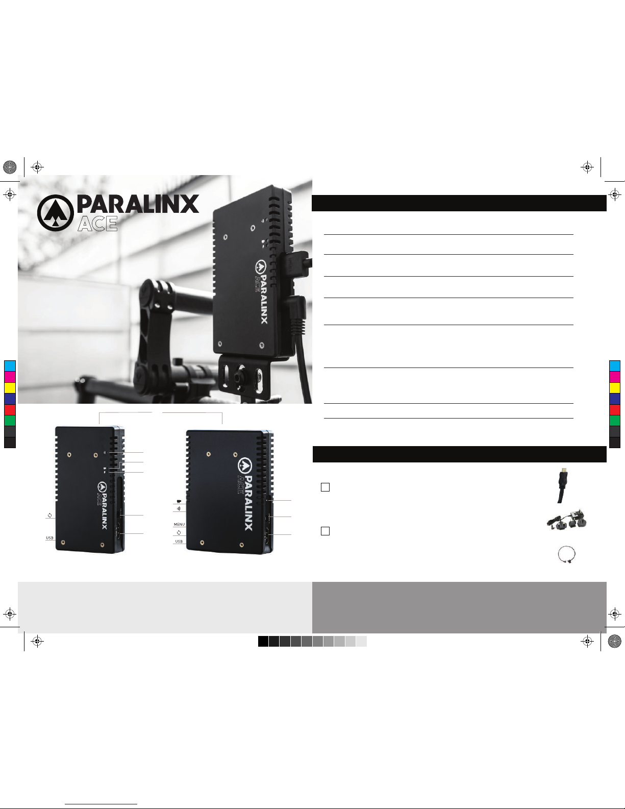
A: Reset Button
B: Mini-USB Port
C: Link Status LED
D: Video Status LED
E: Power Status LED
F: 7-17V DC Input
G: HDMI Input
H: Video Status LED
I: Link Status LED
J: Menu Joystick
K: Power Status LED
NEED MORE HELP?
SUPPORT FORUM: http://support.paralinx.net Contains tips, information and all the latest firmware & software updates.
SUPPORT STAFF: [email protected] or call +01 818-934-1535 (Mon-Fri 9am to 5pm PST - GMT -8)
CONNECT AND POWER YOUR DEVICE
1
2
ON-SCREEN DISPLAY OPERATION
ACE HDMI
QUICK START GUIDE
Paralinx Ace is a zero-delay
wireless video transmission
system designed for the most
demanding cinema, video,
broadcast and UAV production
applications. With a latency of
less than 1ms the Paralinx Ace
transmits 1080p60 4:2:2 video up
to 300ft / 100m line of sight over
the fully certified unlicensed
5.1-5.8ghz band.
Resets all configurable options to their factory settings
This screen displays the status of the wireless receiver, along with
the current video resolution, frequency, and link quality (if connected)
Select Pairing to link your receiver with another transmitter. Once
pairing is activated on the receiver, turn on the transmitter and use a
paper clip to hold the reset button (between the DC input and power
switch) for 1 second and release. The red warning LED and link LEDs
will blink to indicate that pairing is active
Select a video output format from this menu to output a test pattern
over HDMI.
Return to the previous video by pressing left on the ‘Menu’ joystick.
Choose when to display the OSD. By default, the OSD is displayed when
the link is down. "Hidden by default" hides the OSD until it is activated
by the joystick. If "Always show OSD" is selected, the OSD will be
displayed unless deactivated by the joystick
This screen displays the status of the current internal
temperature of the unit
Launch the menu by pressing RIGHT while the OSD is active. Exit
the menu by pressing LEFT
Launch the status screen by depressing the Joystick (J), and cycle
through the screens by pressing the Joystick up, down, left or right
PAIRING
OSD SETTINGS
Displays the model and serial number
STATUS SCREENS
MENU OPERATION
MAIN STATUS
TEMPERATURE STATUS
TEST PATTERN
RESET ALL SETTINGS
DEVICE INFO
Connect the output from your video source to the HDMI input (G) on the
Paralinx Ace transmitter. Connect either the HDMI output from the Paralinx
Ace receiver to the video input on your monitor.
Connect power to your Paralinx Ace transmitter using the included P-Tap to
Barrel cable. Power the Paralinx Ace receiver with the included A/C adapter
or battery plate accessory. If using a battery plate, connect a compatible
battery to the plate, then connect the short cable from the plate to the
receiver’s DC input (F).
P-TAP TO BARREL
AC ADAPTER
SDIHDMI
L
L: Internal Antennas
H
I
J
A
B
C
M
Y
CM
MY
CY
CMY
K
Ace QSG HDMIv3.pdf 1 9/18/15 1:29 PM
Page 2
PARALINX MANAGER SOFTWARE
MOUNTING
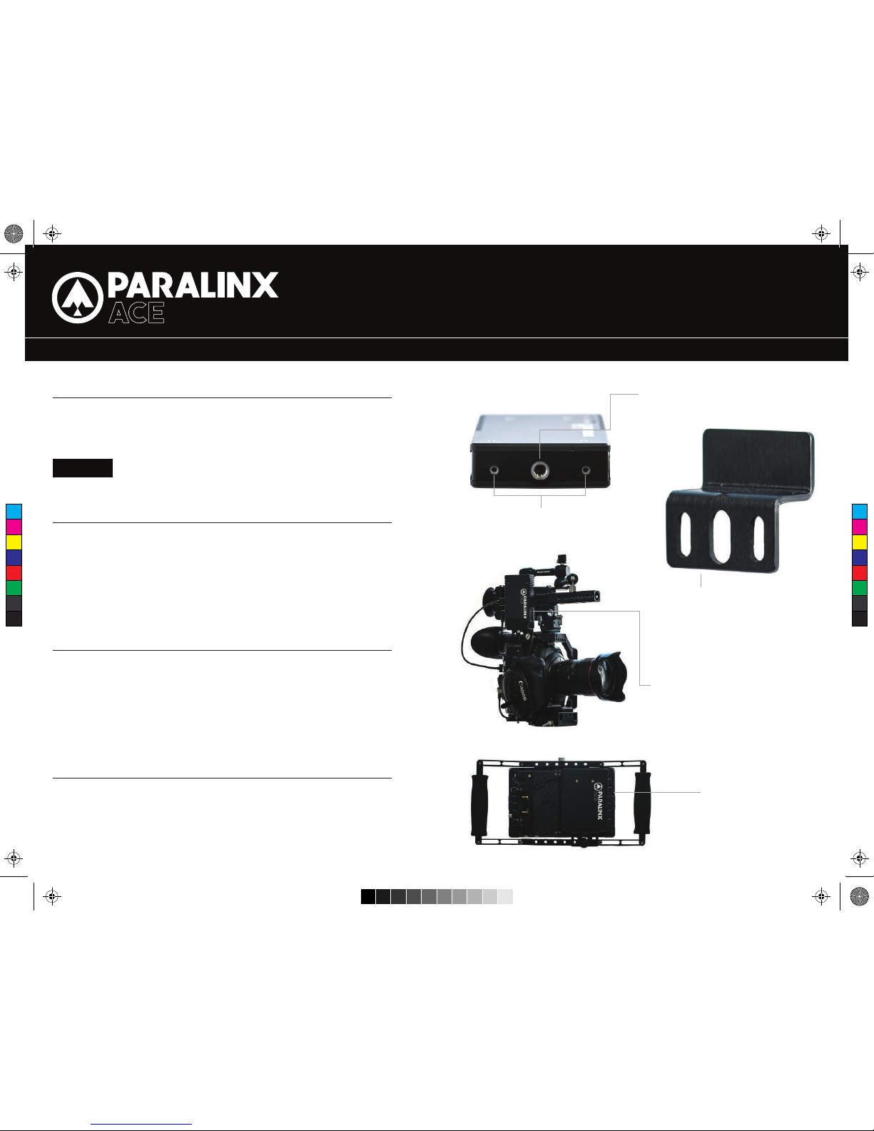
2/56” MOUNTING THREADS
– Keep the transmitter and receiver at close range for 60 seconds after powering on
the devices, allowing them to scan for and select the best wireless channel .
– For best results when using multiple Paralinx Ace in the same area, place the
transmitters and receivers a few feet apart from each other.
– Operation of other wireless equipment may interfere with the Paralinx Ace. For best
results, separate other wireless transmitters and receivers as much as possible.
– Mount the Paralinx Ace transmitter vertically, keeping the antennas clear of any
obstructions.
– Orient the transmitter and receiver so they are parallel to each other.
– For best results, orient the receiver so the front or back has clear line-of-sight to
the transmitter.
CAUTION!
Using a reverse polarity or improperly-constructed power cable can
damage the product and is not covered under warranty!
Paralinx Manager allows you to configure and upgrade your Paralinx Ace. It is
available at www.paralinx.net/downloads. The following configuration is available:
– REGION SELECTION:
Configure Paralinx Ace to comply with your region’s regulations governing use
of the 5GHz spectrum A.
CUSTOM / 3RD PARTY CABLES
DEVICE OPERATION
BEST PRACTICES MOUNTING OPTIONS
MOUNTING THREADS ON TX/RX
ACE HDMI TRANSMITTER
MOUNTED TO CAMERA CAGE
QUICK START GUIDE
1/4”- A20 MOUNTING THREAD
ACE MOUNTING BRACKET- ATTACHES
TO BASE OF TX/RX WITH 2/56” SCREWS
AND ALLOWS MOUNTING IN VARIOUS
APPLICATIONS.
ACE RECEIVER MOUNTED
TO BACK OF SMALLHD 7”
MONITOR
2. Test the power cable polarity with ONLY the power cable connected to Paralinx Ace.
3. Do not connect video cables.
1. Check the power cable for shorts and proper grounding.
C
M
Y
CM
MY
CY
CMY
K
Ace QSG HDMIv3.pdf 2 9/18/15 1:29 PM
 Loading...