

Pilots
Manual
Volution Micro
Volution Compact
Volution Macro

WARNING!!!
YOU MUST READ THIS MANUAL AND AGREE TO THE CONDITIONS OF USE
BEFORE USING YOUR PARAJET VOLUTION
Bear in mind that you will use the Parajet Volution and paraglider at your
own risk. Due to the inherent risk in flying the Volution or any motorized
paraglider, no guarantee of any kind can be made against accidents, bodily
injury and/or death. Be sure, therefore, to make all required checks on the
power unit and paraglider before every flight. Never try to fly if you find
any part of your Volution damaged or suspect a malfunction.
NB. This manual is NOT a substitute for flight training. Proper training is essential.
INTRODUCTION
Congratulations on the purchase of your Parajet Volution for motorized
paragliding. We guarantee you have made an excellent choice and wish you
many enjoyable flights and just as many safe landings with your Volution.
Our power units have been designed and produced in our UK factory to
exacting standards. Each Volution is carefully inspected before leaving the
factory. This manual and Parajet power unit carry a placard that clearly
indicates a limit to flight hours. Therefore, use your Volution within the
limits indicated.
Should the purchaser modify the Volution so as to change its original
specifications, the manufacturer’s warranty becomes invalid.
Please read and be sure that you thoroughly understand this manual before
flying the Volution. If there is any terminology or anything else in this
manual which you do not understand, please contact your dealer for
clarification.
WARNING!!! Use of the powered paraglider is at your own risk.


TABLE OF CONTENTS
1. Pre-Flight Checks
2. Flight Safety Precautions
3. Golden Rules for Safe Flying….Important Reading!!!
4. Pre-Assembly Check
5. Fitting the Propeller Blades
6. Assembling the 3-Piece Propeller Guard
7. Charging the Starter Battery
8. Reduction Belt Adjustment
9. Fitting the Weight-Shift Harness
10. Adjusting the Weight-Shift Harness
11. Mixing the Fuel and Oil
12. Prior to Starting the Engine
13. Starting the Engine
14. Activating the Choke Valve
15. Carburetor Adjustment
16. Carburetor Adjustment (continued)
17. Carburetor Adjustment (continued)
18. Engine Running-in Procedure
19. Parajet Volution Specifications
20. Maintenance Schedule
21. Trouble Shooting
22. Storage for a Long Period and Use Thereafter
WARNING!!! Use of the powered paraglider is at your own risk.

PRE-FLIGHT CHECKS
(every 5 – 10 hours of flying)
1
Frame/ Prop
Guard
Check for loose bolts/nuts or cracks
2 Harness Check all belts, material for tears, worn or burnt parts of harness.
3 Propeller
Check for cracks, chips in blades; sufficient prop and guard
clearance; loose or missing prop bolts/nuts.
4 Gas tank
Remove cap, check inside and outside for cracks and holes. Check
bolts are tight on top of tank. Check fuel line for scuffs or kinks.
Remove dirt or change filter if blockage is discovered.
5 Crankshaft
Turn prop slowly, listen for compression and check for “grinding
metal” sound
6 Reduction unit Check for loose bolts and excess play in propeller shaft bearings.
7 Reduction belt
Check for proper tracking, belt squarely in Pulley track. Look for
cracks or worn spots on belt.
8
Cylinder head
Crank case
Check for cracks and oil leakage.
9 Spark plugs
Check gap clearance (0.8 mm ± 0.1) check for burnt electrodes and
carbon deposits. (every 10 hours)
10 Throttle lever Throttle lever/cable move smoothly and return.
11 Kill switch Button depresses and returns.
12 Starter motor Pinion gear activates and returns. Grease if necessary.
13 Electrics Check for broken wires and loose connections.
14 Battery terminals Check for loose terminals, heat bubbles, corrosion etc.
15
Carburetor
settings
Check idling, and full power rpm settings. Adjust as directed in this
manual- see Carburetor Adjustments.
1

FLIGHT SAFETY PRECAUTIONS
• The Parajet Volution XT 180 Aero engine has been run-in prior to shipment. This
means that your Volution is ready to fly. It is important however that excessive
throttle is NOT used for at least the first 10 hours of flying. For example, do NOT
depress the throttle fully for more than 30 seconds at a time. A well run in engine
will outperform an engine that has been run at full power for long periods right from
the start. You can potentially damage a new engine with excessive throttle.
• The Volution Paramotor unit is to be used only after having received adequate and
proper training from a qualified motor paragliding instructor.
• Max weight capacities for paramotor pilots flying a Parajet Volution range
paramotor:
Parajet Volution Model Max Pilot Weight
Micro
80Kg
Compact
100Kg
Macro 160Kg
• The Volution should only be used with canopies designed for motor paragliding.
• Always conduct a check of all components before every flight.
• Always wear a helmet, flight shoes and gloves when flying the Volution.
• Always stay clear of moving parts such as propellers, pulleys and belt.
• Always stay clear of hot engine parts and muffler.
• Do not fly low level over water, woodland, or potentially hazardous landing
areas. Do not fly into controlled airspace or over built up areas, it essential
always to consider a safe landing area should you experience an engine failure
or loss of power.
• Before starting the engine check the area is clear and shout “CLEAR PROP”
• Always ensure that the power unit is switched off when not in use. The main power
switch is to be found on the left side of the machine just behind the harness.
2

SOME GOLDEN RULES !!!
1. Never place your engine downwind of your wing.
2. Have you enough fuel to get there? Better too much than too little!
3. Check for any loose articles that could trail or fall into the propeller while flying and
fasten them securely.
4. If you spot a problem, not matter how small, deal with it NOW!
5. Always put on and fasten your helmet before clipping into the harness.
6. Always carry out full pre-flight checks before launching.
7. Don’t fly into danger – over water, tree, power lines etc where an engine failure will
leave you in trouble.
8. Try not to fly in the turbulence of your own wake or that of others, especially at low
altitude.
9. Except for collision avoidance, making a sharp turn against the torque effect during
steep climbs can be dangerous: you may rapidly stall and enter a spin.
10. Avoid downwind low flying: it drastically reduces your options.
11. Be sensitive to mechanical problems early. A noticeable change in engine tone or a
new vibration may spell trouble. Land and check it out!
12. Remember, not everyone enjoys your engine noise. Care must be taken when flying
near livestock.
13. Never take-off towards areas of potential rotor, towards trees or buildings on the
lee side of a hill.
14. Never touch any part of the propeller guard when the engine is running.
15. Always be aware of the weather, never fly if large cumulus clouds are brewing and
never fly in the rain.
17. Never fly below the lee side of a hill, rotor is dangerous!!
3

PRE-ASSEMBLY CHECK
Be sure to identify all components after unpacking your Volution unit. If any parts are
found defective do not assemble. Contact your dealer or the manufacturer immediately.
Parajet International Ltd: Main enquiry Line + 44 8700 116618
List of Components
1. Main Chassis 8. 3 Piece Propeller Guard
2. Engine Cylinder 9. Air Box and Carburettor
3. Drive Belt 10. Carbon Fibre Propeller Blade
4. Drive Pulley 11. Propeller Retaining Disc
5. Main On/Off Switch 12. Muffler and Exhaust Pipe
6. Harness 13. Battery Box
7. Rubber Skid Pads 14. Fuel Filler Cap
10
11
6
5
14
12
8
4
13
7
3
2
1
9
4
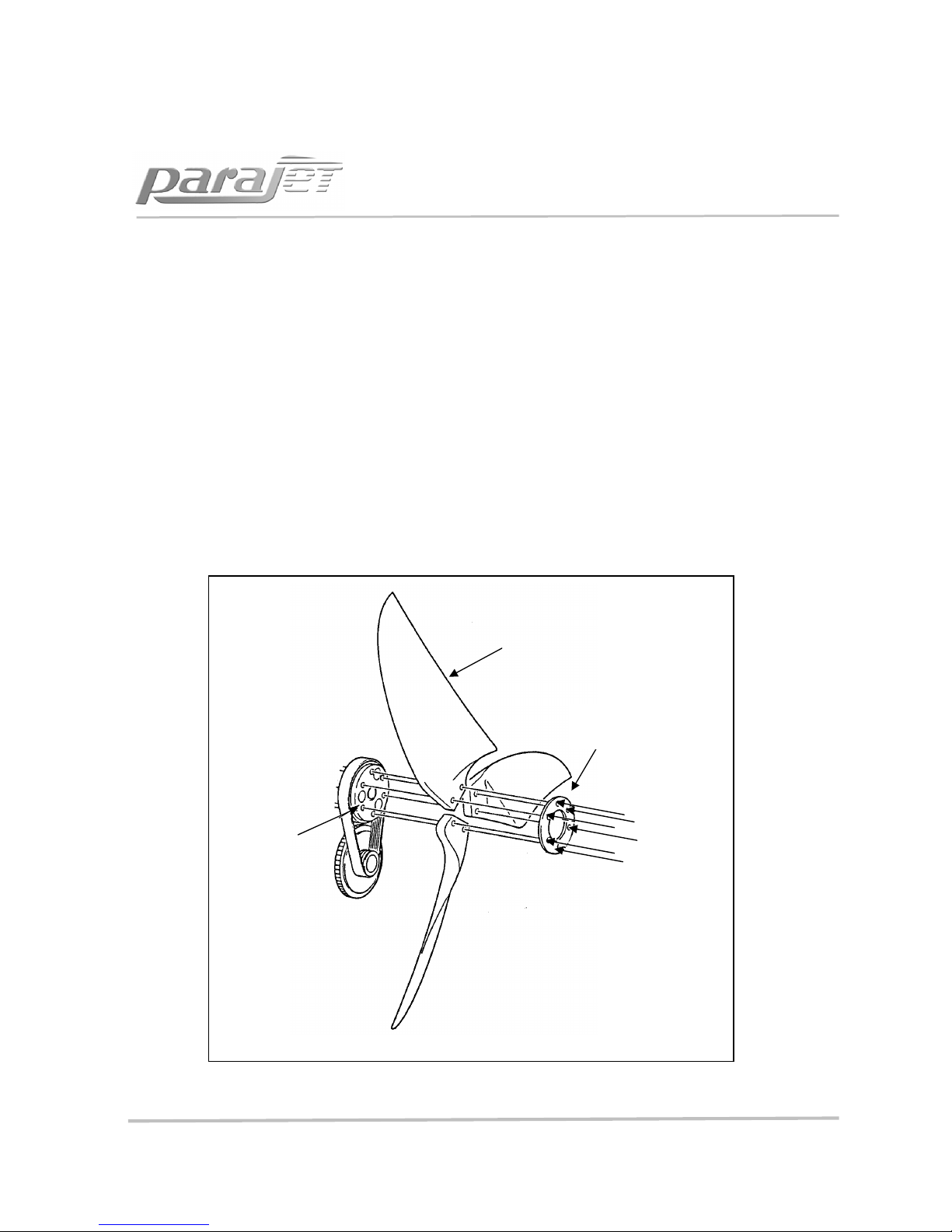
FITTING THE PROPELLER BLADES
Fit the 3 propeller blades to the driven pulley in the order outlined below
1. Insert 2 of the 6 (M8 x 60mm) bolts into the prop disc and locate a single blade in
position. Ensure that each bolt has both a split spring washer then normal spreader
washer located on its shank before locating in the prop disc.
2. Locate a single blade in position on these two bolts and lightly screw the bolts into
position on the driven pulley.
3. Follow the same procedure for each blade but do not tighten the bolts until all three
blades are in position.
4. Finally tighten each bolt with equal torque hand tight only (be careful not to over
tighten and crush the carbon fibre propeller hubs)
Note – When installing the propeller, the propeller blade bolts should not be overtightened or the base of the propellers could be damaged, distorted and weakened.
Prop Disc
M8 x 60
Screws
Driven
Pulley
Propeller Blade
5

ASSEMBLING THE 3-PIECE PROPELLER GUARD
Fit the three pieces together as shown in the illustration below. The two lower sections should
be clicked into position first. The top section can then be clicked into position, to do this lightly
press the curved central support onto its aerofoil connector and simultaneously locate the two
circular side connectors. DO NOT PRESS FIRMLY INTO POSITION UNTIL THE OUTER RING
CONNECTORS ARE LOCATED. Next locate the left and right hand outer ring connectors. Lightly
press them into position but do not depress the button clips. Now that all the connection points
are in position, the central upright should be firmly pressed into position and the button clip
depressed to lock this position. The outer ring connectors can now be locked in also. This
process require a little technique, but once developed can be snapped together and
disassembled in under a minute. This is the fastest and most durable design of propeller guard.
Note - The propeller guard is designed to prevent canopy lines and other foreign objects from
being drawn into the propeller and are not intended to protect the pilot. Therefore,
always use extreme caution and never touch any part of the propeller guard while flying or
running the engine on the ground.
Left
: Internal guard
vertical support slots
through chassis holder
before lower connectors
are locked in position
Right: Upper cage
support is located before
being snapped firmly into
position.
6

CHARGING THE STARTER BATTERY
Every Volution should arrive with the battery installed in position and ready charged. Do not
however expect the battery to be fully topped up at the time of shipping. For this reason it is
advised that you top up your starter battery before attempting to fly your Volution.
USE THE PARAJET CHARGER SUPPLIED WITH YOUR UNIT
Note: When your Volution is being flown regularly it will not be necessary to charge the battery
as the in-built generator charges it automatically.
However, if you do not fly your Volution for more than 4 weeks your battery will require
charging, simply plug the Parajet charger into the charging socket on your power unit for a
minimum of 24 hours
1. To remove the battery, simply unlock the harnesses upper retaining bar from the chassis. Fold the
harness down away from the body of the power unit to expose the electronics case.
2. Remove the case cover by hinging the top out first, the bottom can then be pulled up and out of
position.
3. The battery will now be exposed at the base of the electronics box. The positive terminal is insulated
with a press-fit rubber boot. This must be pulled back to expose the terminal that must be disconnected.
4. Disconnect both terminals before removing the battery.
5. IMPORTANT: When you replace the battery be sure to push the insulating boot firmly over the positive
terminal. Failure to do so will cause the battery to short out on the body of the machine which could
result in fire or damage
.
Open Electronics Case
Battery Position
7

REDUCTION BELT ADJUSTMENT
The transmission belt is well adjusted at the time of shipment, but it could become slack
during initial operations. When necessary adjust it so as to keep it always in an optimum
state of tension. Referring to the picture below adjust reduction belt tension as outlined
in these steps. A high pitch revving noise from the engine is a sign that the belt has
become loose. Be sure to tighten the belt as soon as possible or you could damage it.
1. Remove the propeller from the driven pulley.
2. Loosen the prop shaft retaining nut and then screw (A) NB. They will be very tight!!
3. Insert the 5mm hex key into the hole in the side of the prop shaft. (B)
4. To tension the belt, firmly rotate the shaft clockwise. This in turn will enable the
eccentric prop shaft to increase the belt tension. It will be very stiff to move.
5. Once the belt has reached the required tension simply re-tighten the prop shaft
retaining screw and nylock nut. (see diagram below for belt tension setting)
A
B
Left
:
Prop Shaft
retaining screw also
has a nylock security
nut on the opposite
end. Loosen this 4
turns before undoing
main screw (A)
Right
:
Use 5 mm hex
key provided and slot
into drilled hole in
propeller shaft. Then
rotate propeller shaft
hard clockwise to
tighten or counter
clockwise to loosen.
Left
: Shows correct
belt
tension. You should be
able to push 2 - 3mm
movement with your
thumb.
2 – 3 mm
8

FITTING THE WEIGHT-SHIFT HARNESS
The weight-shift design enables pilots to control flight direction purely by shifting centre
of gravity in the harness. To do this simply lean in the desired direction and swing one
leg over the other to accentuate the turn. This creates a very efficient smooth turn
which requires no brake input.
Fitting the weight-shift harness:
1. Start by locking the harnesses upper
retaining bar onto the chassis as shown
below. NB. Ensure Button Clip locates
properly and pops into hole as arrowed..
2. At the base of the harness on the
reverse side there are 2 steel rings
pressed into the webbing tabs. These
line up with 2 corresponding M6
threaded inserts located in each chassis
upright approximately 10cm from the
base.
3. Using the two M6 x 12mm socket screws
and large flange washers tighten the harness
webbing into position against the chassis
uprights.
4. At the front of the harness are 2 webbing
loops. Using the stainless steel shackles
attached to the swing arms attach the
webbing loops to the first hole in the swing
arm.
5. Attach carabiner connection points to the
corresponding weight setting on the swing
arms. (See next page)
9

ADJUSTING THE WEIGHT SHIFT HARNESS
To adjust this type of harness to the optimum weight setting, position the hang-point
mallion and off-set pin as shown below. The weight ranges are given in the diagram.
IMPORTANT – If the harness is not set up correctly it will result in poor handling and
uncomfortable flying. It is vital therefore that the steps described below are followed
accurately.
CAUTION!!! If the pilot is too heavy for the chosen harness setting this will cause the
Volution to ride up on the pilots back. This makes for an uncomfortable flying position
and also causes the top of the propeller guard to press near to the paraglider brake
handles which is potentially very dangerous. If you suspect this it is important that you
land as soon as possible and re-set the hang points moving them one or two settings
forward.
NOTE – Due to the dynamic nature of this harness it may take some flying time to
become accustomed to the flying style. It may also take a few flights to decide which
hang-point position is most comfortable and effective for you. You will notice that on
full power the flying position is more upright and that when you reduce throttle the
position is more laid back. The engine off position is designed to be similar to the free
flying position which is more comfortable and improves weight shift for thermalling.
(65kg
– 75kg)
(55kg
– 65kg)
(100 –
110kg)
(75kg
– 90kg)
NB. The Volution weight shift harness is designed to offset the
torque reaction of the propeller. This enables the pilot to fly
straight even on full power. The system uses the pilot’s weight to
counter the torque by off-setting both karabiners to the right as
the pilot sits in the harness. See arrows above.
Important: Always ensure that both rubber off-set covers are
fully tightened in position pointing to the left as you look at the
harness before you get in to fly (as above) If you are sitting in the
harness they should both point to the right. This is essential!!
10

MIXING FUEL AND OIL
Use only unleaded regular petrol (95 - 98 octane) and high-grade 2-stroke oil for aircooled engines. BP Super 2-Stroke and Castrol TTS are recommended.
Other oils can be substituted but any oil used should be for air-cooling chemical
synthesis and medium rotation. Check with your manufacturer or our service centres or
any authorised Parajet dealer for the best type of oil available in your area.
1. Mix petrol and oil at a ratio of 50:1 (100mm Oil for 5 litres of unleaded petrol)
2. Shake and mix fuel and oil well.
3. Always use freshly mixed petrol and oil not more than 4 weeks old
4. Use standard unleaded fuel (95 – 98 octane is standard)
5. Only use recommended oil.
FILLING THE FUEL TANK
1. Remove the tank cap. (rotate counter clockwise)
2. Pour the fuel mixture into the fuel tank.
3. Fill tank to 20mm below level of filler (8.5 litres) For maximum flight range fill to the
top (3- 4mm beneath cap level total of 9.5 litres)
4. Tighten fuel cap securely. (be sure not to cross thread the cap as it will not seal
correctly)
Note
• Do not fill above this level.
• Be careful of fuel spillage and wipe dry should any occur.
• Be sure the fuel is clean. Although there is a fuel filter in the fuel tank Dirt, dust
and other foreign objects can clog the filter and cause the engine to run poorly
or stop.
Caution!
• Never leave the engine running when refueling.
• Observe the ‘No Fire’ rules; keep all inflammable objects well away from fuel.
11

PRIOR TO STARTING THE
ENGINE
1. Check carefully the surrounding area before taking out your unit.
2. Be sure to choose a flat bit of ground which is well ventilated. Do not start the
engine indoors or other poorly ventilated areas.
3. Be sure nothing is within 3 meters of your unit.
4. Conduct a complete pre-flight check of your unit, especially looking for oil and gas
leaks. Check the unit carefully for loose nuts or bolts, bent or damaged frame or any
other type of damage.
5. Check level of fuel mixture. Be sure it is freshly mixed (less than 4 weeks old).
6. Check immediate area near the propeller for lines, ropes, clothing and anything that
could be caught in the moving propeller or drive pulleys.
7. Pilots with long hair should be especially careful to cover their head.
Warning!!! - Stay Clear of this Area !!!
• Warn persons nearby before starting the engine- Make it a habit to shout ‘Clear
Prop’ in a loud and clear voice.
• The turning propeller can cause considerable damage and injury.
• Do not start engine indoors or other poorly ventilated areas.
• Be sure area is free from anything that could be entangled in propeller.
• Use only freshly mixed 50:1 regular petrol and oil recommended by Parajet. The
most common reason for engine damage is improper oil or petrol
• Only fill tank with the engine off and only after it has cooled down.
• Follow all “No Fire” rules.
Warning!!
Keep clear of moving propeller
Keep objects away from propeller
Danger Area. Always ensure
this area is clear of people
12
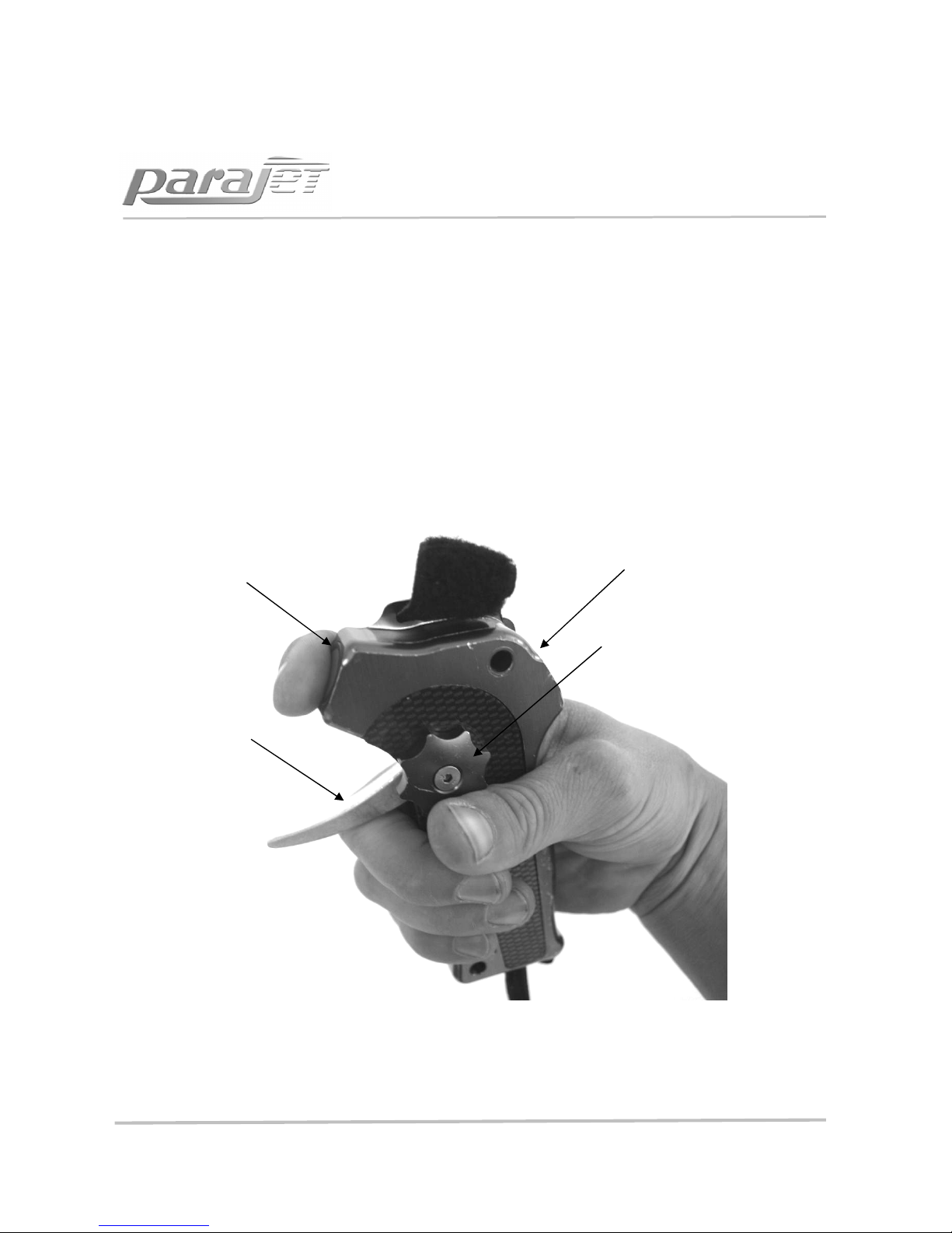
STARTING THE
ENGINE
1. Push the choke valve into ‘choke’ position (closed. See following page for details)
2. Turn on the main switch located at the right side of the electronics case behind the
right side of the harness.
3. Make sure the throttle lever is in the idle position, DO NOT GRIP HANDLE.
4. Firmly hold the frame from the harness side. Rest your full body weight against the
harness side of the chassis using your shoulder and knee.
5. Hold down the green starter button until the engine fires once.
Warning: Release green starter button immediately after engine fires once, failure
to release immediately will cause the engine to flood.
Engine Kill Button (RED)
Cruise Control Knob
CW: To Lock
CCW: To Unlock
Starter Switch (GREEN)
Throttle trigger
13

ACTIVATING THE CHOKE VALVE
6. After first exhaust note is heard, push the choke valve back to its operating position.
IMPORTANT! Release the start button immediately after engine fires once or you
will flood the engine!!
7. If the engine fails to start repeat steps 1 to 5 again.
8. After the engine starts, warm it up for two or three minutes at low speed
revolutions.(be sure to read the section on engine break-in)
STOPPING THE ENGINE
1. Stop (kill) the engine only after releasing the throttle grip and allowing the engine to
return to idle speed.
2. Hold down the Stop button until the engine dies completely.
3. Turn off the Main switch. This cuts power to the starter motor and has been designed
as a safety measure. Make it a steadfast rule to turn off the Main Power to avoid
inadvertent starts and accidents.
RE-STARTING THE ENGINE
When the engine is warm, leave the choke lever in the operating/open position and
follow step 2 through to 7 outlined in the section above ‘Starting the Engine’.
In flight, the pilot can restart the engine when flight conditions are suitable. Be sure the
throttle is in idle position when re-starting the engine.
Choke valve shown in “RUN” position. Use this
position to run the engine for flying
Choke valve shown in “ON” position. Use this
position to prime and start the engine initially
14
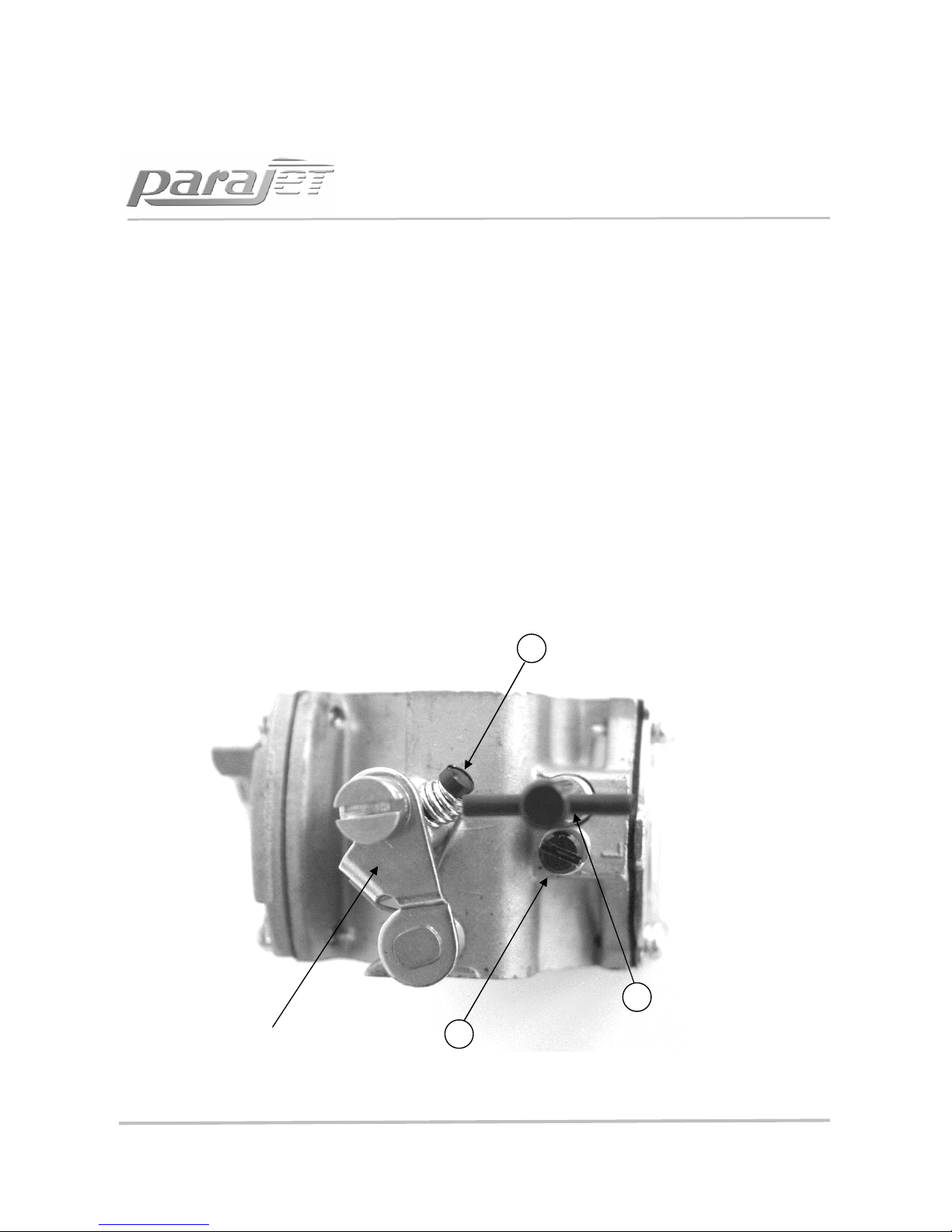
CARBURETOR ADJUSTMENT
Warning! When running the engine on the ground for the carburetor adjustments and
checking the thrust power, be sure to place the unit on flat and level ground, rest your
full body weight against the chassis, and check the throttle cable is clear of propeller.
The power and idle needles control the lubrication received by the engine. Basic
adjustments are made with:
1. Idle adjust screw – clockwise to increase and anti-clockwise to decrease.
2. L-needle - clockwise to decrease mixture flow to carburetor, anti-clockwise to
increase flow, (for initial acceleration).
3. H-needle - clockwise to decrease flow, anti-clockwise to increase flow, when throttle
is fully open for acceleration.
Low Jet Screw (set 1½
from seat and screw CW
to adjust)
High Jet T-Screw (set
1½ from seat and
adjust for top end
power
Idle Adjust Screw. (use
this to set desired idle
speed)
Main throttle lever
activated by trigger
grip
Carburetor Details:
2
1
3
15

CARBURETOR ADJUSTMENT
(continued)
Note – Adjustments should be done carefully. Warm-up the engine for 3 to 4 minutes
before attempting to make any carburetor adjustments. Be aware that changes in the
barometric pressure, humidity, and ground altitude affect the carburetor and engine
performance.
Step 1 – With the engine off , start by turning the needles all the way in (clockwise) but
do not force them. Check to see that the tension springs are lightly depressed. Then set
the Low and High needles at 1 ½ turns front seat. These are factory settings. This puts
both on the rich side and leaner adjustments can be made as needed. Any other
adjustments should be made to ±⅛ turns in either direction. Too lean an adjustment can
cause improper lubrication and damage the engine.
Step 2 – Adjust the idle adjust screw to stabilize idle rpm at 2000rpm ± 100. If this
setting is too difficult to obtain, turn off the engine and restart before trying again.
Step 3 – Engage full throttle and check acceleration. If the engine fails to accelerate
smoothly or seems to stop, then turn the L-needle ⅛ clockwise . Further adjustments by
⅛ turn can be made but should this fail to correct the problem then another cause for
poor acceleration is suspected (probable). Trouble shoot further or contact your dealer
or a Parajet service representative for assistance.
Step 4 – Adjust the idle adjust screw again to stabilize idle at 2000rpm ± 100. Again
engage full throttle for 5 to 10 seconds and return to idle. Repeat Steps 4 and 5 until idle
is stable. Do not exceed ½ turn clockwise. The L- needle should always be at least 1 full
turn open from seat (CCW).
(H) Needle rotate 1/8 turn CW or
CCW for top end power
(L) Needle rotate 1/8 turn CW or
CCW to set first 70% of rev range. If
engine dies when throttle is
opened, turn CCW ¼ turn
High Jet T-Bar
Adjust by hand
Low Jet Screw
Use screw driver to adjust
16

CARBURETOR ADJUSTMENT
(continued)
Step 5 – Now Adjust for maximum power at 7600 rpm +/- 100. If max rpm is less than
this, turn the H-needle 1/8 turn clockwise. (Parajet Supply RPM Tachometer as an
accessory, should you wish to make fine adjustments as described please contact us)
Caution!! – Do not close the H - needle (turn clockwise) more than this – 1 and 1/8 turns
from seat - overheating from too lean a mixture will cause engine failure or even
complete seizure!! It may take some time to find the optimum setting and for the
engine to stabilize at high rpm. Carefully observe and judge the best setting of the H –
needle. It is safer to error 1/16 or 1/8 CCW and lose 100 to 200 rpm than to tune for
more power and higher.
Step 6 – Again engage full throttle and return to idle. Continue this until the optimum
high rpm and stable idle are reached.
Step 7 – The carburetor is pre-set at the factory before shipment and you should
remember that the H - needle should not be adjusted and set for maximum rpm. It is
best to find maximum rpm but set the H – needle a few hundred rpm below the peak, in
a range close to 7800rpm.
Note – Proper carburetor settings can be noticed by inspecting spark plugs after every
hour of engine use. A properly adjusted carburetor will reveal spark plug ceramic colour
to change from white to a medium brown. A carburetor that is too rich will be black and
sooty. Also, numerous oil droplets will appear on the propeller. White or very, very light
brown colour reveals too lean a mixture and caution here is advised.
Also pay attention to the reduction belt tension. If the belt is too loose then engine
response may seem good but the engine could over-rev to 8300rpm or more. Be sure
belt tension is within recommended tolerance (see reduction belt tension adjustment in
this manual)
17

ENGINE RUNNING IN PROCEDURE
The Volution engine undergoes a thorough inspection before shipment during which
each engine is run for 1 hour as a preliminary running-in process. For the best engine
performance it is necessary to follow our running in procedure during your first 10 hours
of flying. This is a simple process and most importantly it means that you can fly your
Volution right away with no lengthy ground running process.
For the best results it requires that you never remain on full power for more than 30
seconds at a time during flight.
Directions:
After take-off you may remain on full power during climb out for up to 1 minute (max)
It is then important to back-off the power and sit at cruise rpm and fly level for 1 – 2
minutes approx before using full power again.
If you wish to climb high do so in stages climbing on full power for 30 second intervals
then allowing the engine to settle at cruising flight rpm or slow climb for a minute or so.
After the first 10 hours of flying you are free to climb using the throttle for longer
periods….
However….
The key to a long lasting, high performance engine is to treat it with some respect. Do
not dwell on full throttle for long periods as the engine becomes hot and this reduces
the life span of the bearings and mechanical components. As with any engine, using it
well within its designed limits ensures that you will receive the longest life from it.
Resulting in less maintenance costs and servicing time.
18

PARAJET VOLUTION SPECIFICATIONS
Propeller and Cage Guard
Dimensions (Micro) 940mm cage diameter (84cm propeller diameter/ 33 inch)
Dimensions (Compact) 1090mm cage diameter (98cm propeller diameter/ 38.5 inch)
Dimensions (Macro) 1350mm diameter (123cm propeller diameter/ 48.5 inch)
Material Aluminium Duralumin 6082 T6
Engine Specifications
Model Parajet 180 XT (Manufactured by Parajet)
Displacement 180cc
Type Air-cooled 2 stroke Engine
Max rpm 7600 rpm
Fuel 50:1 gasoline/oil
Capacity (Micro) 9.5 litres
Capacity (Compact) 9.5 litres
Capacity (Macro) 11.5 litres
Starter Electric in flight recharge
Propeller 3-blade full carbon fibre Scimitar Design
Guard 3-piece snap-on, quick assembly system.
Reduction 2.44 : 1 Micro 2.7 : 1 Compact 3.19 : 1 Macro
Dry weight 24.5 kg Micro 26kg Compact 27kg Macro
Thrust (Micro) 48kg
Thrust (Compact) 56kg
Thrust (Macro) 68 kg
Flight Time (Micro) 1.5 Hours
Flight Time (Compact) 2 hours
Flight time (Macro) 4 hrs
Standard equipment
Electric starter,
In-flight charging, power socket.
19

MAINTENANCE SCHEDULE
EVERY 5 HOURS
1 Spark plugs
Check colour (white or black) burnt electrode. Connector cap
locks with pressure, makes locking sound
EVERY 10 HOURS
1 Air cleaner
Remove and wipe clean. If excessively dirty with carbon and oil
then clean with kerosene
2 Air Funnel Wipe with smooth cloth.
3 Muffler
Check for cracks and loose band or bolts. Run finger inside exhaust
pipe –an oily film should be found. No oily film suggests that
oil/gas mixture is too lean so the carburettor needs adjusting.
EVERY 50 HOURS
1
Compression
check
Compression in the cylinder must be no less than 1 pound under
normal reading.
2 Piston rings Remove muffler, visual check of rings for stuck or broken areas.
3 Cylinder wall Check for burns near exhaust port and sides of wall.
20

TROUBLE SHOOTING
If any problems occur with your engine you can refer to the following trouble shooting
table for correction.
Problem
Check Point
Correction
Engine does not start
• No spark
There is spark but the
engine doesn’t start.
• The plug cap is disconnected.
• The coil wire is not connected to
the plug cap terminal.
• The plug wire is not connected.
• The spark plug is dirty.
Fuel does not reach the
carburetor. (Check the fuel pipe.)
Fuel does not reach the cylinder.
(remove the plug and check the
plug electrode).
Excessive fuel is fed into the
cylinder
(check the plug electrode.)
• Attach the plug cap.
• Connect coil wire to plug cap
terminal.
• Connect plug wire.
• Clean spark plugs or replace
them.
• Press green starter button
again.
Press green starter button
again
Take out plug and press
starter several times. (be sure
to earth plug)
There is an initial explosion but
the engine does not run
continuously.
• The choke lever is not set at
“driving” position.
• The idle screw is not properly
adjusted.
• The air filters clogged.
• The breathers of the fuel cap are
clogged.
• The fuel filter is dirty.
• The L needle of the carburetor is
not properly adjusted.
• Set the choke lever to
“driving” position.
• Make adjustments according
to 8 – (1).
• Clean air filters.
• Clean breathers.
• Clean fuel filter.
• Make adjustments within the
range in 8 - (2)
The engine does not accelerate
through low rpm range.
• The choke lever is not set at
“open” position.
• Warm-up is not sufficient.
• The adjustments of the L needle
are not proper.
• Set choke lever to “open”
position.
• Warm up engine.
• Make adjustments within the
range in 8 – (2)
The engine does not accelerate
through high rpm range.
• The fuel filter is dirty.
• The breather of the fuel cap are
clogged,
• H needle adjustments are not
proper.
• Clean fuel filter.
• Clean breathers.
• Make adjustments with range
8 – (2)
Vibration excessive
•
Fasteners are loose.
• Tighten fasteners securely.
21

STORAGE FOR A LONG PERIOD AND USE THEREAFTER
Always follow instructions below after your engine has been stored over a long period.
When your engine has not been used for more than 4 weeks
1. Ideally remove fuel from the fuel tank and replace with fresh fuel for best
performance and starting reliability. Older fuel looses a % of volatiles through
evaporation even inside the fuel tank (which is marginally porous) and starting the
engine becomes more difficult. The exhaust becomes oilier and you may also notice
a drop in engine power. Using old fuel will not harm your engine up to about 2
months at which point the properties in the two stroke oil will deteriorate and you
will risk damaging the engine through poor lubrication.
2. You may find that the starter battery charge is low, it is important to keep this
topped up regularly with the charger supplied. If the battery is low then start
charging at least 12 hours before you intend to fly to avoid disappointment as the
engine requires a well charged battery to start reliably. The charger can be left
connected and charging for up to 4 days with no adverse affect on battery or
charger.
When the engine is not used for more than 3 months
1. In order to prevent the piston rings and bearings from rusting, remove the ignition
plug and apply a small amount of special purpose oil through the plug hole. After
pulling the starter handle several times lightly for lubrication, install the ignition plug
back into the engine.
2. After cleaning and drying the various portions of the engine, wrap the engine in a
vinyl bag.
3. Store the engine in a dry and well ventilated location away from direct exposure to
sunlight.
4. Parajet supplies Briggs and Stratton ‘Fuel Fit’ it is recommended that you use this
additive in your fuel to help clean out the system after a long period of no use. It
helps to remove residue in the carburetor and fuel system.
22

Parajet International LTD
Email: sales@parajet.com
Beaumont Business Centre Tel: + 44 (0) 1747 861 368
Mere, Wiltshire, BA12 6BT UK www.parajet.com
 Loading...