

Paragon Outdoor GZ3D User Manual
5
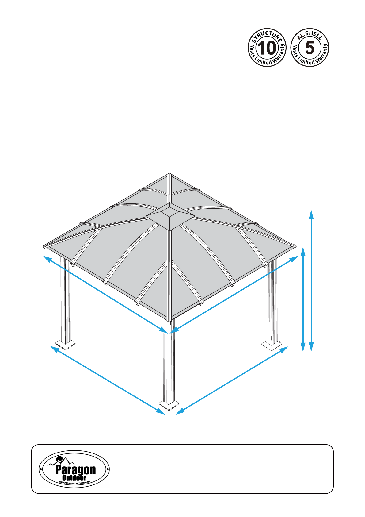
Gazebo GZ3D
Aluminium Composite Roof Panels
Assembly Instructions
11’2’’
10’6’’
9’7’’
7’
11’2’’
10’6’’
Paragon Group USA
Customer Service:(877) 782 4482 Email:cs-outdoors@paragongroupusa.com

Introduction
Thank you for purchasing the Gazebo GZ3D.
When properly assembled and maintained, this gazebo will provide many years of enjoyment!
These instructions include helpful hints and important information needed to safely assemble and properly
maintain the gazebo. Please read these instructions completely before you begin.
Our patented gazebo has been designed for easy assembly. All steps can be completed by a team of
four people. The assembly should take about two hours.
Before Starting Assembly:
CAREFULLY READ ALL THE INSTRUCTIONS BEFORE YOU BEGIN AND FOLLOW THE
STEPS IN THE ORDER THEY ARE PRESENTED.
1. Make sure you have all the necessary parts:
Compare the contents of all cartons to the List of Parts. If any parts are missing or damaged, or
you have any questions, please contact Customer service:
2. Lay the parts out in separate staging areas:
The List of Parts has the corresponding step number referenced to each part. We recommend that
while you go through
each step in these areas. This will save you time and effort during assembly.
the list, make staging areas for each step and place the parts necessary for
(877)782 4482
before beginning assembly.
3. Select a Location:
When selecting a location for your gazebo, a at level area is essential and if possible with proper
water drainage and easy access to power and water, if neccessary.
Choose a sunny, level position away from overhanging trees and power lines and protected from the
wind as much as possible. Locate underground pipes or cables before preparing the site or anchoring
the gazebo.
Note: You may assemble the gazebo on a hard level surface and mov
finished. Make sure that there are no obstacles between the assembly area and th
e it to its
nal location when
nal position.
4. Prepare a Foundation:
After choosing a location, proper preparation of the site is recommended. The site must be level.
If the site is not level, create a base slightly larger than the outside dimensions of the gazebo using a
perimeter of two by fours filled with either soil, sod or gravel.
Make sure the base is square by measuring the diagonals from both directions and making sure
they are equal. The gazebo is secured with pegs into holes cast with concrete.
If you decide to have a concrete base, it is best to contact a reliable contractor to make sure it is
and level. Make sure you have checked with your local authorities regarding any required building
permits.
at
5. Make sure you have the proper tools:
Tape Measure 2 Small Step Ladders
Work Gloves Wooden Mallet
Safety goggles Scissors and knife
Phillips
Spirit Level Hex Key (included)
Screwdriver
Liquid soap or WD40 Lubricant
NOTE: A cordless drill with Phillips head bit is highly recommended but not essential.
of 242
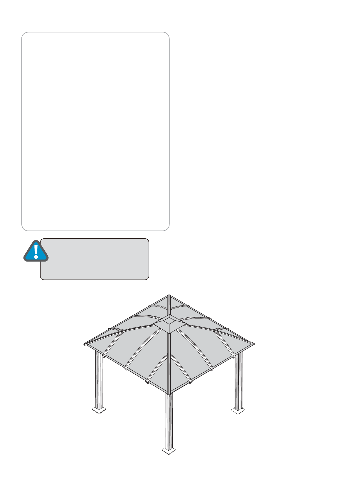
Safety Advice
Table of Contents
•
The gazebo must be positioned and fixed
on a flat level surface.
•
Dispose of all plastic bags safely. Keep
them out of the reach of children.
•
Keep children and pets away from the
assembly area until the work is completed.
•
Always wear shoes, gloves and safety
goggles when working.
•
Take special care not to touch overhead
power lines with the aluminium profiles.
•
Do not attempt to assemble the gazebo in
windy or wet conditions.
•
Do not position your gazebo in an area
exposed to excessive wind.
•
If using power tools or a ladder, always fol-
low the manufacturers safety instructions.
•
Hot items such as recently used grills,
blowtorches etc. must not be stored in the
gazebo.
•
Make sure the gazebo complies with local
building codes.
ATTENTION:
ATTEMPT TO
THE GAZEBO
DO NOT
ASSEMBLE
ALONE!
Introduction................................................. 2
Table of Contents......................................... 3
List of Parts.................................................. 4
Step 1 Assembling the Corner Profiles................. 6
Step 2 Assembling the Rails............................... 8
Step 3
Step 4 Securing the Gazebo to the ground......... 12
Step 5
Step 6
Step 7
Upper Roof Profiles.............................. 17
Step 8
Attaching the Rails to the Corner Profiles
Installing the Lower Roof gable Profiles
Installing the Lower Horizontal Roof Profiles..
Installing the Roof Panels and
Installing the Plastic Caps......................... 22
......... 10
.. 13
16
General Order of Assembly
Step 1: Assembling the Corner profiles
Step 2: Assembling the Rails
Step 3: Attaching the Rails to the Corner Profiles
Step 4: Securing the gazebo to the ground
Step 5: Installing the Lower Roof Gable Profiles
Step 6:
Step 7: Installing the Roof Panels and
Upper Roof Profiles
Step 8:
Installing the Lower Horizontal Roof Profiles
Installing the Plastic Caps
of 243
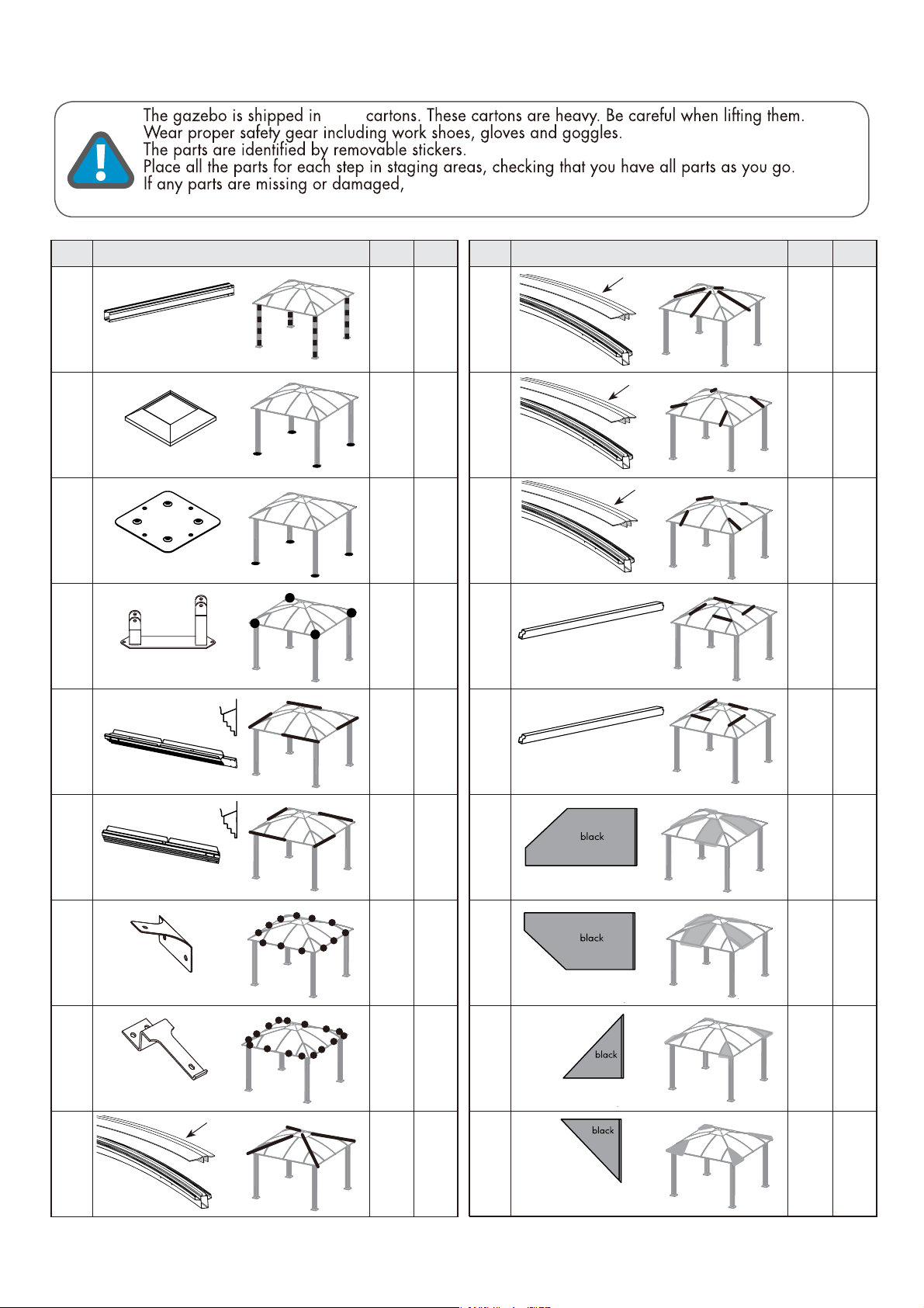
List of Parts
Customer Service:(877) 782 4482 Email:cs-outdoors@paragongroupusa.com
four
contact customer service before beginning assembly:
No. Profile Qty
41
Corner
Profile
2190mm
42
Support Frame
43
Support Plate
44
Corner Roof
Connector
Step
1
1
1
1
No. Profile Qty
10A
1520mm
10
Roof
Gable Profile
1540mm
11A
935mm
4
4
4
11
Roof
Gable Profile
942mm
12A
935mm
4
4
12
Roof
Gable Profile
942mm
4
431
825mm
Step
5,7
5,7
5,7
6
Rail
1808mm
Rail
1633mm
Inner Roof Connector
Outer Roof Connector
9
Roof
Gable Profile
2152mm
9A
2075mm
441
45
2
825mm
46
2
Aluminium Composite
Roof Panel
127
168
2
2
4
5,7
4
16
Aluminium Composite
Roof Panel
17
Aluminium Composite
Roof Panel
18
Aluminium Composite
Roof Panel
side
side
side
side
6
451
7
4
7
4
7
4
7
of 244
No. Profile Qty
Step
No. Profile Qty
Step
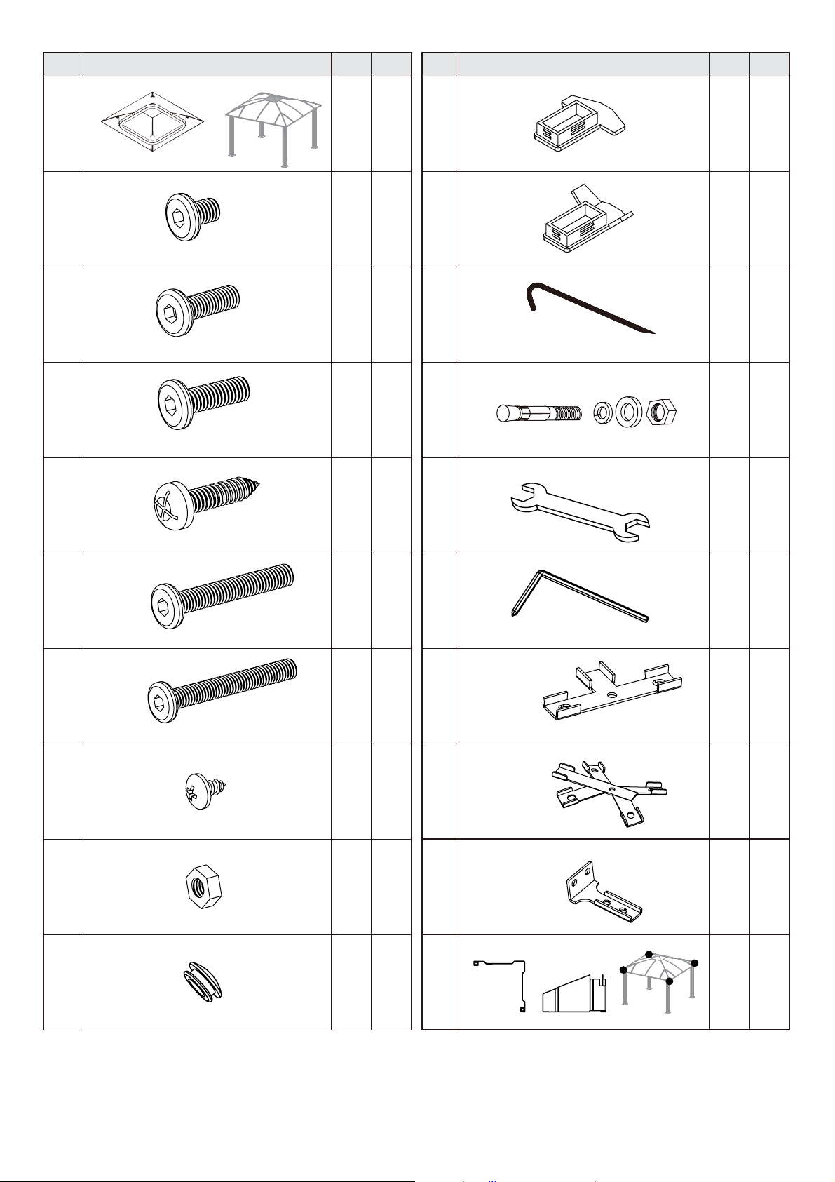
19
20
21
22
23
Roof Top Cover
Screw M6*8
Screw M6*12
Screw M6*18
1
16
16
148
32
5
2
5
2,3
5,6
1,6
29
30
31
32
33
Plastic Cap #1
Plastic Cap #2
Ground Spike
Concrete Bolt
12
4
16
16
1
4
4
4
4
6
24
25
26
27
Screw M6*25
Screw M6*33
Screw M6*38
Screw ø 4*8
Nut M6
8
60
16
8
Spanner
5
7
7
5
34
Magnetic Hex Key
35
T - connector A
36
X - connector B
37
Roof top connector
3
1
4
5
4
5
5
8
28
Plastic Cap #3
32
3
38
We included some extra screws and bolts for your convenience.
of 245
4
6
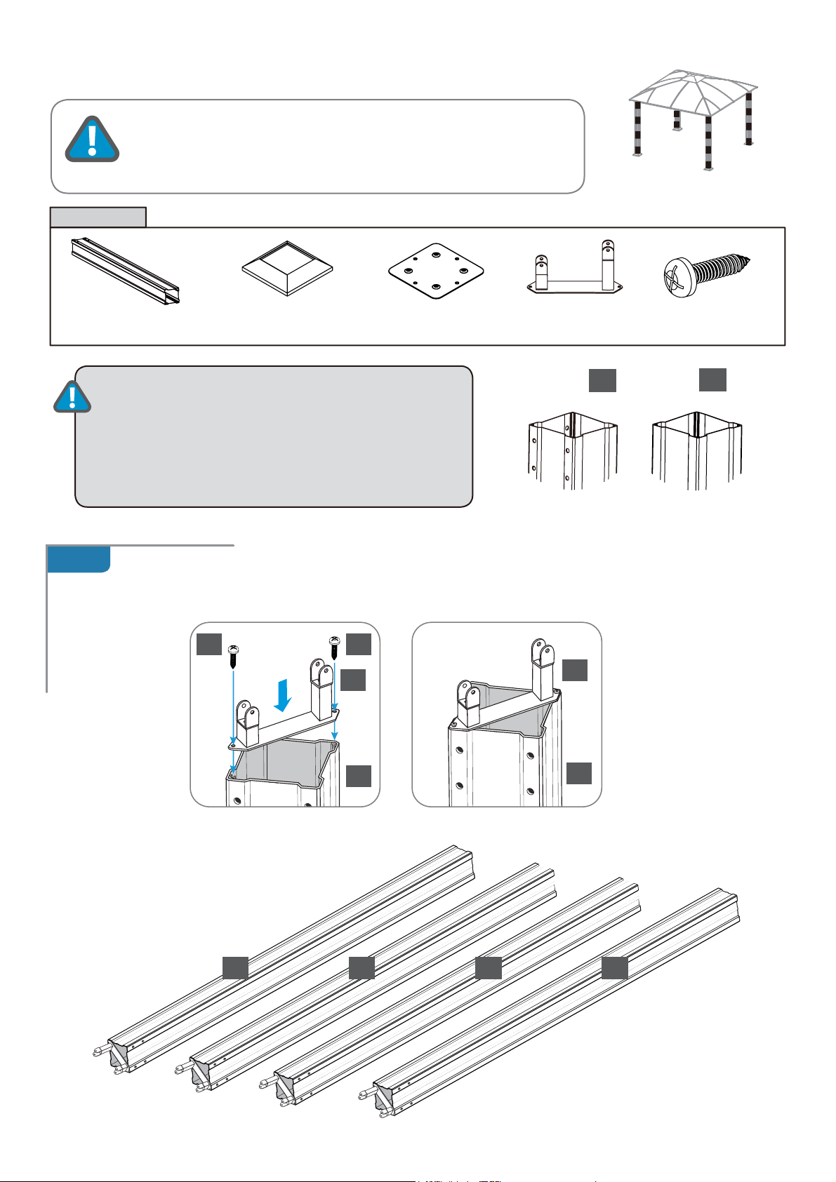
STEP 1
Assembling the Corner Profiles
Components
Corner profile (1)
x 4
ATTENTION:
Place all the parts on a level surface
Make sure the pieces are in the correct positions before assembling.
Carefully follow the order of assembly to ensure an easy installation.
Wear proper safety gear including work shoes, gloves and goggles.
Support frame (2)
x 4
The corner profile (1) has two screw
.
Support plate (3)
holes to connect it to the roof connector (4)
and 8 pre-drilled screw holes to attach rails (5,6) in
step 3 at its top end.
It has two screw holes to connect it to the support
plate (3) at its bottom end.
x 4
Roof connector (4)
x 4
1
Top end Bottom end
Screw (23)
x 24
1
1.A
Place corner profiles (1) parallel to each other on the ground. Attach one roof connector (4) to each top
end as shown and fasten with screws (23).
23 23
4
1
4
1
x 4
1 1 1 1
of 246
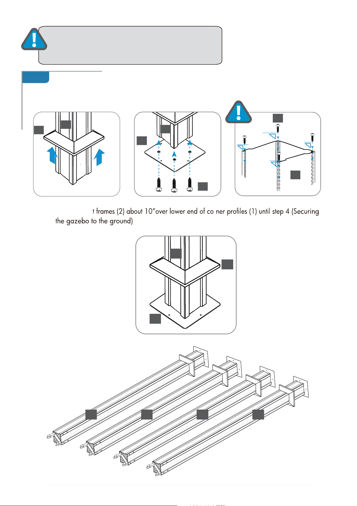
ATTENTION:
support frame (2) if you purchased the screen netting
(GZ3DS or GZ3DXLS).
Note: Do not need to assemble
1.B
Slide support frames (2) over lower end of corner profiles(1).
Attach support plates (3) to corner profiles as shown, using two screws(23) for each plate, make
sure all screws are perpendicularly into the profile holes.
23
2
1
3
Leave suppor r
1
1
23
1
2
3
x 4
1 1 1 1
of 247
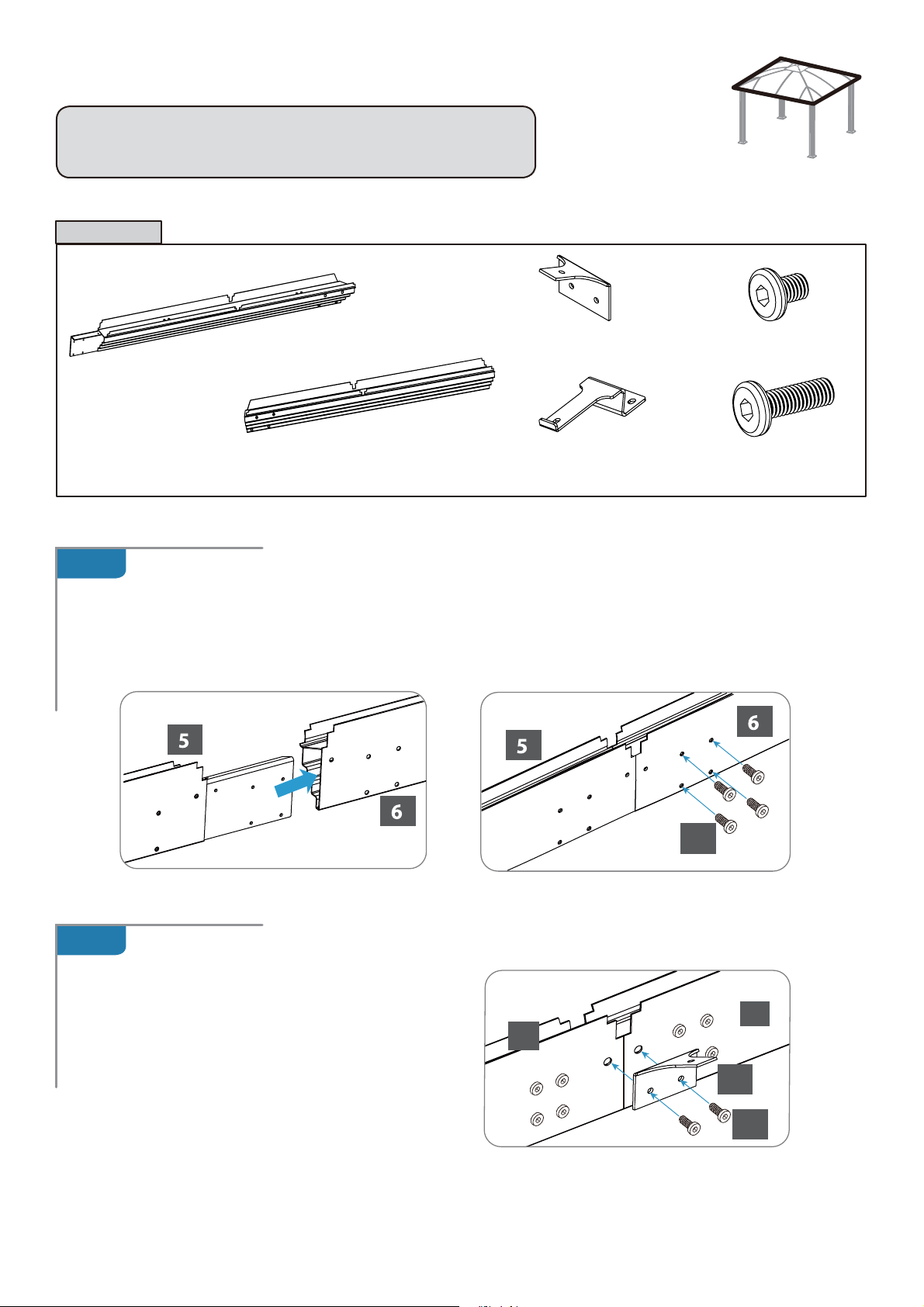
STEP 2
Assembling the Rails
NOTE:
parts to be inserted into Rails (6).
Components
2.A
The Rails (5) have a preassembled connecting
Rail (5)
x 4
Insert connecting part of rail (5) into blunt end of rail (6) as shown.
Attach with four screws (20). Repeat to create four sets of rails.
Rail (6)
x 4
Inner Roof Connector (7)
x 12
Outer Roof Connector (8)
x 16
Screw (20)
x 16
Screw (22)
x 56
2.B
20
Attach inner roof connector (7) to
each rail set as shown, using two
screws (22).
6
5
7
22
of 248
 Loading...