

Paragon 2000 Plus Turbo Owner's Manual
Owner’s Manual
INCLUDES
User, Maintenance, Service, and Installation
Instructions
2000 Plus Turbo Manual
Keep this booklet for service log and future reference
For use in Great Britain and Ireland.
Literature NO 5052 (ISS 5)
IMPORTANT
This appliance is guaranteed for 12 months subject to conditions. The 5 year extended parts
warranty will only be valid if the annual service recommended in this manual has been
completed and appliance has been registered online.

Contents
EXTENDED FIVE YEAR PARTS WARRANTY .................... 2
Benchmark Scheme ..................................................... 3
SECTION ONE Introduction (user instructions) .......... 5
SECTION TWO Operation (user instructions) ............. 7
SECTION THREE Cleaning (user instructions) .............. 8
SECTION FIVE Replacement Parts (user instructions)
................................................................................... 15
SECTION SIX Appliance Specification (installation
instructions) ............................................................... 15
SECTION SEVEN Regulations and Warnings
(installation instructions) .......................................... 16
SECTION EIGHT Siting the Appliance (installation
instructions) ............................................................... 18
SECTION NINE To Install the Appliance (installation
instructions) ............................................................... 22
SECTION TEN Check Operation of Fire (installation
instructions) ............................................................... 32
SECTION ELEVEN Maintenance Instructions
(maintenance instructions) ....................................... 34
SECTION TWELVE Wiring Diagram (maintenance
instructions) ............................................................... 38
SECTION THIRTEEN Fault Finding Instructions
(maintenance instructions) ....................................... 38
GAS FIRE COMMISSIONING CHECKLIST ..................... 42
SERVICE RECORD ........................................................ 43
EXTENDED FIVE YEAR PARTS
WARRANTY
In order to validate your extended 5 years parts
warranty please read the Benchmark Scheme on the
opposite page and ensure your installer has filled in the
appropriate checklist.
This in no way reduces your statutory rights
Your warranty commences from the date of purchase
and you must retain your receipt or invoice as proof of
a purchase date.
THIS EXTENDED WARRANTY SPECIFICALLY EXCLUDES
GLASS AND SOFT REFRACTORY COMPONENTS, THE BULB
AND ANY BATTERIES.
Terms and Conditions
1. The appliance must be installed by a GAS SAFE
registered person.
2. The appliance must be used in accordance with
the user’s instructions.
3. The appliance must be serviced annually by a GAS
SAFE registered person.
4. The benchmark and service log must be correctly
filled out and the record of annual services must be up
to date and supported by receipts in each case.
5. This warranty is not transferable and relates to the
original installation only.
6. The appliance has not been subjected to misuse or
accident or been modified or repaired by any
person other than the authorised employee or
authorised representative of Charlton and Jenrick
Ltd.
7. The registration form must be returned within 1
month of purchase.
Technical Help Desk 01952 200 444

Benchmark Scheme
Charlton and Jenrick Ltd is a licensed member of the Benchmark Scheme which aims to improve the standards of
installation and commissioning of domestic heating and hot water systems in the UK and to encourage regular servicing
to optimise safety, efficiency and performance. Benchmark is managed and promoted by the Heating and Hotwater
Industry Council. For more information and the full code of practice please visit www.centralheating.co.uk
Please ensure that the installer has fully completed the Benchmark Checklist on the inside back pages of the installation
instructions supplied with the product and that you have signed it to say that you have received a full and clear
explanation of its operation. The installer is legally required to complete a commissioning checklist as a means of
complying with the appropriate Building Regulations (England and Wales).
All installations must be notified to Local Area Building Control either directly or through a Competent Persons Scheme.
A Building Regulations Compliance Certificate will then be issued to the customer who should, on receipt, write the
Notification Number on the Benchmark Checklist.
This product should be serviced regularly to optimise its safety, efficiency and performance. The service engineer
should complete the relevant Service Record on the Benchmark Checklist after each service.
The Benchmark Checklist will be required in the event of any warranty.
It is a requirement that the gas fire is installed and commissioned to the manufacturer’s instructions and the data fields
on the commissioning checklist completed in full.
To instigate the guarantee, the gas fire needs to be registered with the manufacturer within one month of the
installation.
To maintain the guarantee, it is essential that the gas fire is serviced annually by a Gas Safe registered engineer. The
service details should be recorded on the Benchmark Service Interval Record and left with the householder.
4 LT5052 (ISS 5)
Important
For future reference we suggest you record the following details here, and keep the receipt as proof of purchase.
This information may be asked for when you contact the helpdesk.
MODEL:
2000 Plus Turbo Manual
Serial No.
This information can be found on the label attached to the packaging and on the data badge, which is located on
the base of the appliance behind the control cover.
Retailer Name:
Address:
Date Of Purchase:

www.charltonandjenrick.co.uk 5 LT5052 (ISS 5)
SECTION ONE Introduction (user instructions)
Consumer Protection Information
As manufacturers and suppliers of heating products, we take every care, as far as is reasonably practicable, that
these products are so designed and constructed as to meet the general safety requirement when properly used and
installed. To this end, our products are thoroughly tested and examined before despatch.
IMPORTANT NOTICE: Any alteration that is not approved by the appliance manufacturer could invalidate the approval
of the appliance, operation of the warranty and could affect your statutory rights.
Health and Safety Notice
Important
This appliance could contain some of the materials, indicated below, that could be interpreted as being injurious to
health and safety. It is the users / installers responsibility to ensure that the necessary personal protective clothing is
worn when handling these materials, see below for information.
Artificial Fuels, Mineral Wool, Insulation Material, Refractory/Ceramic Fibres, Glass Yarn - may be harmful if inhaled,
may be irritating to skin, eyes, nose and throat.
When handling avoid inhaling and contact with skin or eyes. Use disposable gloves, facemasks and eye protection.
After handling wash hands and other exposed parts. If a vacuum is used for cleaning the coals or cleaning after
servicing / installation it is recommended that it be of the type fitted with a HEPA filter.
Disposal of refractory/ceramic materials. To keep dust to a minimum these materials should be securely wrapped in
polythene and be clearly labelled ‘RCF waste’. These materials are not classified as ‘hazardous waste and should be
disposed of at a site licensed for the disposal of industrial waste.
The PARAGON 2000 Plus MANUAL TURBO is designed and tested to the requirements of the European Standard
EN 509.
The PARAGON 2000 Plus MANUAL TURBO is intended for decorative purposes.
The PARAGON 2000 Plus MANUAL TURBO is designed for use in locations, which do not have a conventional
chimney. This is achieved by extracting the products of combustion of the fire using a centrifugal fan via a ducting
system connected through an outside wall. Located behind the fret are the fan control unit, with on and off
switches, and the gas control.
The PARAGON 2000 Plus MANUAL TURBO incorporates features, which prevent the appliance being used should
the flue become blocked, or the fan fails. The effective operation of the flue is monitored by a device which, when
operated, supplies gas to the burner. If a low flow condition occurs whilst the fire is in operation the fan will
automatically switch to the high-speed mode to try and clear the restriction. If the restriction is cleared, the fan
will return to the normal running mode or, if not the gas to the burner system will be shut off.
The PARAGON 2000 Plus MANUAL TURBO incorporates a safety device in the form of an Oxygen Depletion System,
which constantly monitors the oxygen in the room and will cause the fire to switch off if the oxygen level reduces,
this may be due to insufficient ventilation or a blocked or restricted flue. If this regularly occurs do not attempt to
relight the appliance until a qualified engineer has checked it, the problem may not be due to lack of air or a
defective flue. THIS DEVICE MUST NOT BE OVERRIDDEN.
When the appliance is not in use the gas control and the fan should be switched off.
6 LT5052 (ISS 5)
Operating the fan without the gas being switched on can reduce excessive drafts from the flue when the fire is
not in use.
IMPORTANT INFORMATION
The PARAGON 2000 MANUAL TURBO is available in two versions Natural Gas or LPG (Propane Gas Only). The
markings (G20 for natural gas or G31 for propane) on the packaging and the data badge specify the gas for which
the appliance has been factory set. NOTE: This appliance should only be used on the appropriate gas specified.
It is not suitable for conversion from one gas to the other.
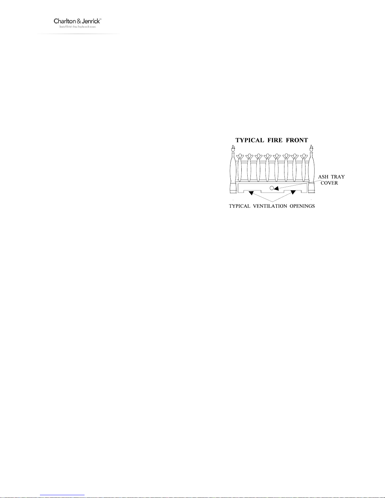
The cast fire front (fret) or approved fascia must be positioned in front of the fire whilst it is burning and must
conform to the following:
It must be made from non-combustible material.
Its general construction should enable it to stand firmly across the full
width of the burner.
The design of the fire front (fret) must have a removable ashtray
cover (lower section).
The ash tray cover must have cut-outs and or holes which
provide ventilation to the underside of the burner.
The effective area of ventilation through the ash tray cover must be
greater than 1365mm2 (2.12 sq. ins.)
Failure to install the appliance correctly could lead to prosecution.
In GB (Great Britain), the appliance must be installed by a competent person i.e. CORGI-registered, in accordance
with the GAS SAFETY (INSTALLATION AND USE) REGULATIONS, The Building Regulations (or The Building
Regulations (Scotland) or The Building Regulations (Northern Ireland)) and The Current I.E.E. Wiring Regulations,
if appropriate.
In IE (Ireland), the appliance must be installed by a competent person and installed in accordance with the
current edition of I.S.813 Domestic Gas Installation, the current Building Regulations and the current ETCI rules
for electrical installation, if appropriate.
This appliance has a naked flame, as with all such fires it is recommended that a fireguard should be used for the
protection of children, the elderly, and infirm. Fireguards should conform to BS 6539 (1984) (Fireguards for use
with solid fuel appliances).
During initial firing an odour may be evident. This is the starch binder used during the manufacture of the fibre
components of the fire, and there are no harmful effects produced.
During the normal operation of the fire some black staining may appear on some parts of the fuel bed. This is
quite normal and adds to the appearance of the appliance. However, if excessive black staining does occur it may
be due to the fuel bed being incorrectly laid. This should be checked prior to contacting a service engineer.
Like all appliances incorporating an aerated burner with a fanned flue system a low frequency noise may be
heard.
It is advised that the PARAGON 2000 Plus MANUAL TURBO fanned flued fire is serviced annually as it is more
likely to provide trouble-free operation.
The flue should be regularly checked and kept clear of any obstruction. Refer to Section 3 “Cleaning Fan Outlet.”
In GB (Great Britain) the fire does not normally require purpose built ventilation, but if it as been necessary to
provide ventilation it should be checked periodically to ensure that it is free from any obstructions.
In IE (Ireland) permanent ventilation must comply with the current edition of IS813.
Rubbish must not be thrown onto the fuel bed under any circumstances.
www.charltonandjenrick.co.uk 7 LT5052 (ISS 5)
SECTION TWO Operation (user instructions)
ELECTRICAL CONNECTION
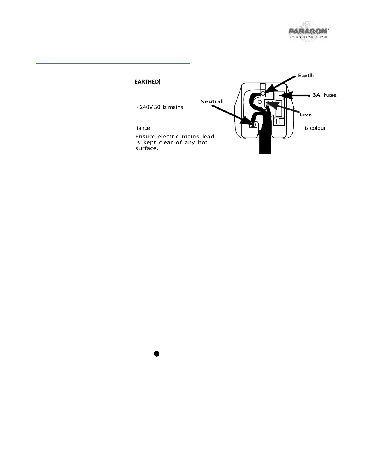
(WARNING: THIS APPLIANCE MUST BE EARTHED)
This appliance is suitable for use on 220 - 240V 50Hz mains
supply only.
The wiring in the mains lead on this appliance is colour
coded as follows:-
Green & Yellow - Earth
Blue - Neutral
Brown - Live
The mains plug terminal should be connected as shown and a 3A fuse must be used to protect the appliance.
The appliance control knob and fan switches are located behind the fret on the left hand side.
The full lighting procedure is as follows: -
OPERATING THE FAN
A. Ensure that the electricity supply is connected and switched on.
B. Lift off the ash pan cover and press the switch marked on. The red light at the base of the control unit will
illuminate and the fan should operate at the high speed. After a short period (up to 20 seconds) the light will
extinguish, the fan speed will reduce and the fire can be lit (see Lighting the Fire).
C. If the red light does not illuminate on initial operation, or the fan does not run press the switch
marked OFF to reset the control and wait approximately 1 min. before repeating steps 'a' and 'b'
above.
D. During normal use the red light may illuminate indicating a flue restriction (this may be due to a
flue obstruction or adverse wind conditions). In these circumstances the fan speed will increase and
if the condition is not corrected in approximately 10 seconds the gas supply will be shut off. The
control knob must be turned to the position and the off switch must be pressed to reset the
control. Before attempting to relight the fire wait 3 minutes. If this occurs refer to Section 3
“Cleaning Fan Outlet.”

8 LT5052 (ISS 5)
LIGHTING THE FIRE
A. Push the control knob in as far as possible on gas control.
B. Turn knob anti-clockwise until a click is heard. The knob will stop at the position marked and a spark
should be seen at the tip of the ignition probe. At the same time the pilot flame should light. KEEP THE KNOB
PRESSED IN FOR 20 SECONDS. Should the pilot fail to light, turn the control knob clockwise to the
position, wait 3 minutes, and repeat the procedure.
C. After lighting the pilot flame the control knob should be allowed to spring out slightly. This will allow you to
turn the knob further anti-clockwise to the position marked . The pilot flame should then ignite the main
fire.
D. It is possible to adjust the height of the flames by turning the control knob between the positions marked
and . Note that the knob 'latches' in position at either end of this movement and must be pushed in
slightly before it can be turned.
NOTE: During normal use the red light may illuminate indicating a flue restriction (this may be due to a flue obstruction or
adverse wind conditions). In these circumstances the fan speed will increase and if the condition is not corrected in
approximately 10 seconds the gas supply will be shut off. The control knob must be turned to the position and the off switch
must be pressed to reset the control.
Before attempting to relight the fire wait 3 minutes.
TURNING OFF THE FIRE
A. Depress the knob slightly and turn fully clockwise to the position.
B. Turn the fan off by pressing the switch marked 'OFF'. The fan should always be turned off when the fire is
not in use.
SECTION THREE Cleaning (user instructions)
Warning: -
Before you clean any part of the appliance ensures that the appliance is turned off and cold.
CLEANING: TRIM, FRET or FASCIA
Abrasive or chemical cleaner should never be used. The fret and trim may be cleaned with a clean damp cloth.
N.B The trim and fire fret should be removed for cleaning. (The trim is held in place by magnetic strips).
CLEANING: BLACK PAINTED SURFACES
www.charltonandjenrick.co.uk 9 LT5052 (ISS 5)
These surfaces should be dusted regularly and any marks removed with a soft cloth.
Abrasive or chemical cleaner should never be used.
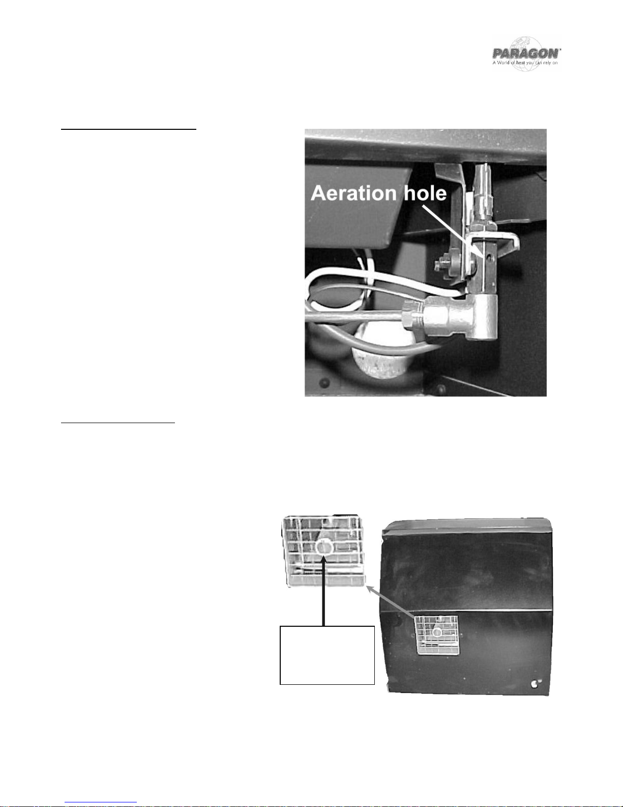
CLEANING: PILOT ASSEMBLY
In some instances you may experience ignition
problems even when the appliance is new. This may be
due to the aeration hole in the pilot body being partial
blocked with dust, pet hairs or other foreign matter.
The source of this debris could be such things as carpet
fibres, decorating or pet etc.
To clean the pilot, remove the fire front and
ashpan. The pilot is located on the right hand side
of the appliance, any debris in or around the
aeration hole should be remove using the nozzle of
a vacuum cleaner. It is advisable not to blow the
debris into the hole as this may cause more of a
restriction and not rectify the problem.
CLEANING: FAN OUTLET
Warning: -
Before cleaning the fan outlet ensure that the appliance is turned off and cold. In addition isolate the appliance from
the electrical supply (i.e. unplug or switch off at the socket).
If the red light adjacent to the on/off switches
does not extinguish or cycles on and off, it
may be that the fan outlet has become
obstructed (e.g. by plants or other objects) or
the pipe which senses that the fan is operating
correctly has become restricted (e.g. spider,
insects or other debris), particularly if the
appliance has not been used for some time. If
appropriate, remove the obstructions from
the fan outlet and, with the aid of a pipe
cleaner or similar object, clean the pipe
located in the centre of the outlet grille. This
should be checked prior to contacting a
service engineer.
Clean pipe with
the aid of a
pipe cleaner or
Ensure fan outlet
is clear and free
from any
obstructions.
10 LT5052 (ISS 5)
Warning: -
Before you clean any part of the appliance ensures that the appliance is turned off and cold.
Use only the fuel bed components provided, no additional parts must be added.
Incorrect positioning of the fuel bed components could result in the excessive black on some parts of the fuel
bed.
Important: - Refer to the Health & Safety Notice located on page 5 of this booklet before cleaning or replacing
any refractory material.
The fuel bed components are delicate and they should be handled with great care.
The loose parts and moulded shapes may be removed for cleaning. They can be brushed very gently with a soft
brush to remove dust or any deposits.
A vacuum cleaner may only be used after the loose components and moulded shapes have been removed.
CARE SHOULD BE TAKEN TO AVOID CONTACT WITH THE REFRACTORY LININGS THEIR SURFACES ARE DELICATE AND
SHOULD NOT BE WIPED OR RUBBED.
It is important that all the fuel bed moulded shapes are positioned as shown in these instructions.
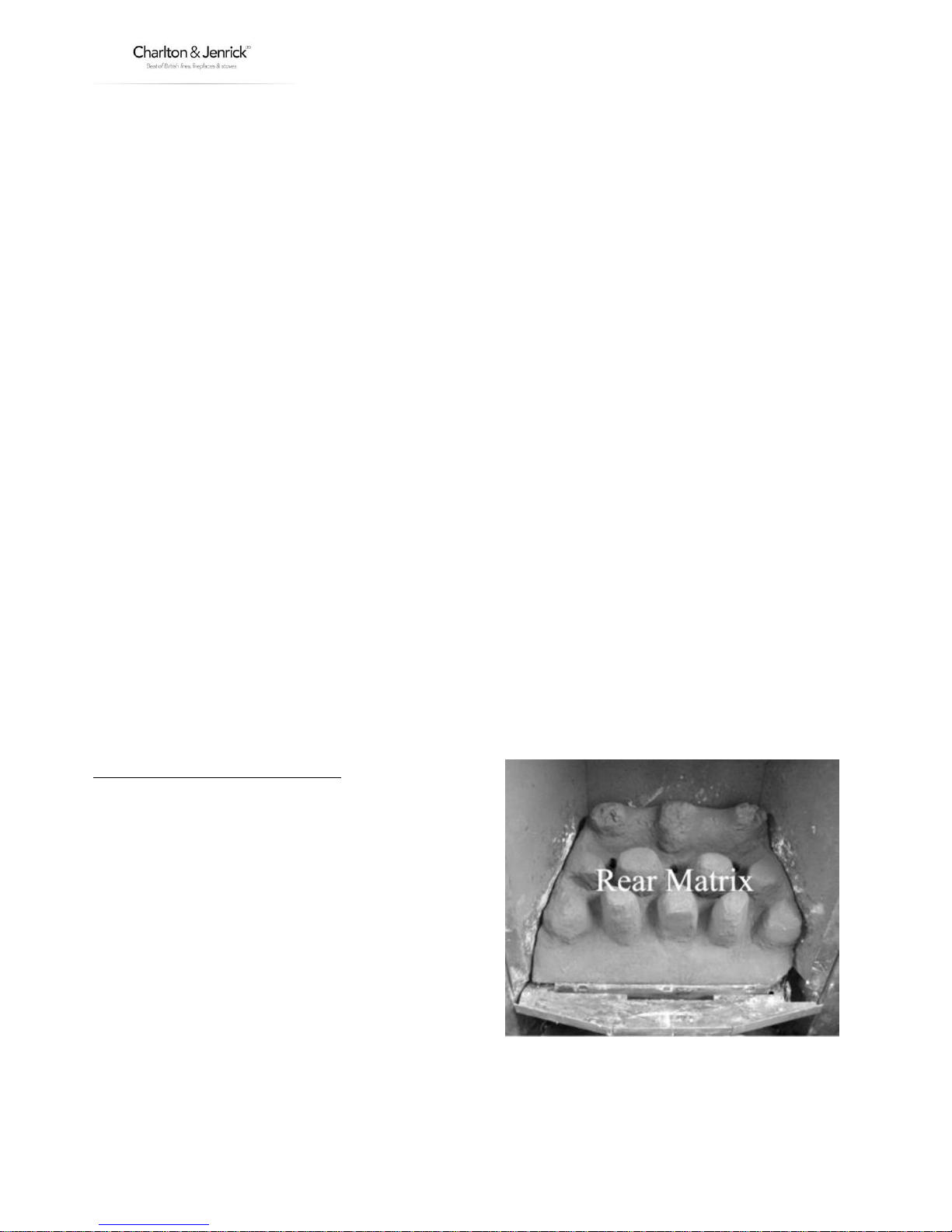
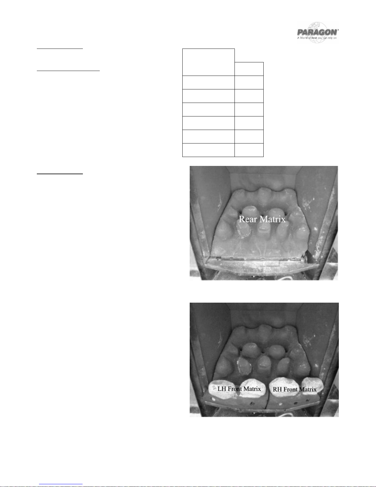
FUEL BED LAYOUT (COAL OPTION)
Ensure the BASE MATRIX is in position as shown. It
should be located against the rear edge of the burner
outlet.
www.charltonandjenrick.co.uk 11 LT5052 (ISS 5)
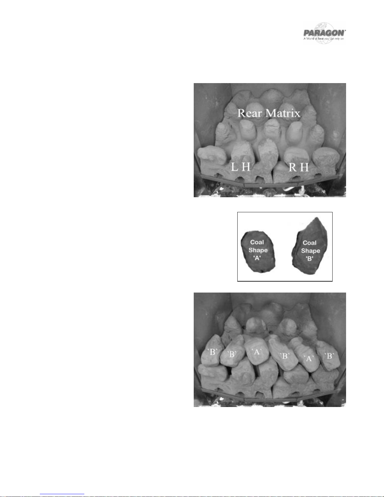
Locate the LEFT HAND and RIGHT HAND FRONT
COALS as shown so that they sit in front of the
burner, positioned behind the front lip of the tray.
Ensure that they lean back against the BASE MATRIX.
Note: It is very important that they are located in
their correct positions. They are marked on the rear
‘L’ for LEFT HAND FRONT COAL and ‘R’ for RIGHT
HAND FRONT COAL.
Separate the coal into the two size groups
The loose coals provided consist of 5 COALS ‘A’ SHAPE and 9 COALS
‘B’ SHAPE.
.
Lay the first row of loose coals “B” and “A” shapes as
shown.
12 LT5052 (ISS 5)
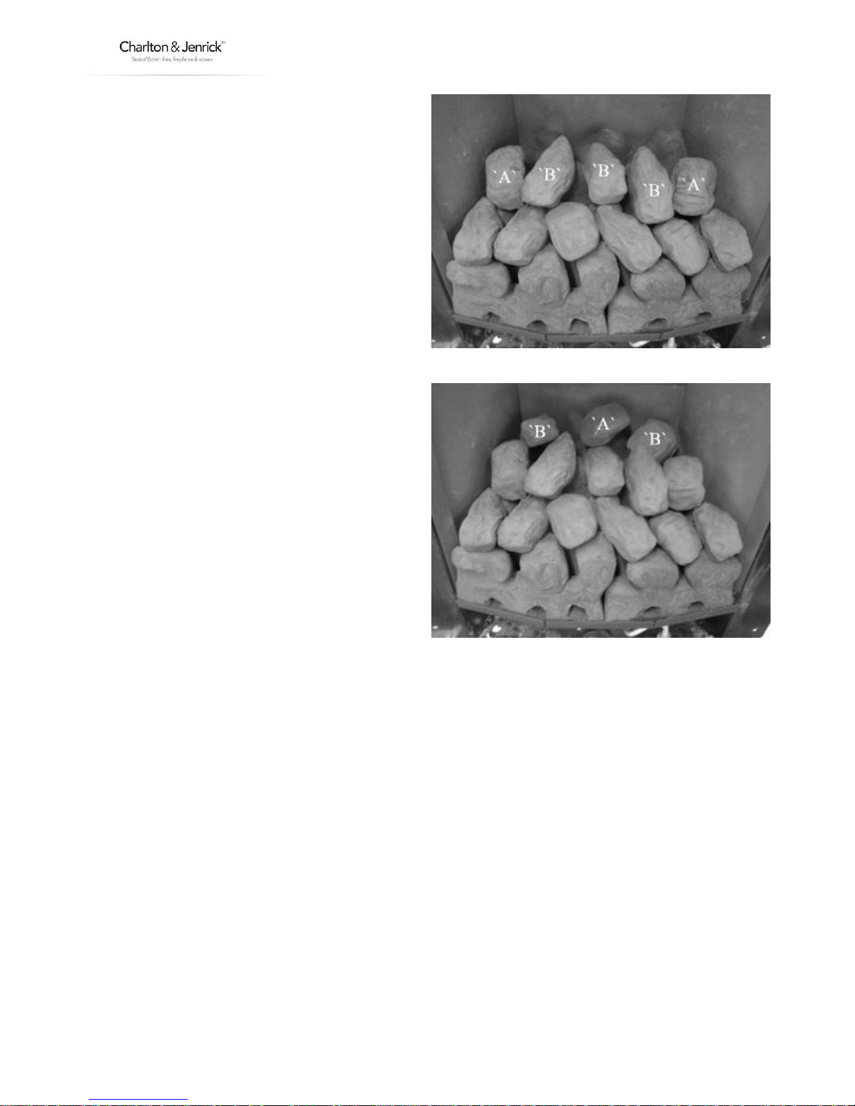
Lay a second row of loose coals “B” and “A” shapes
as shown.
Finally, lay the last three loose coals 2 “B” shapes
and 1 “A” shape
www.charltonandjenrick.co.uk 13 LT5052 (ISS 5)
PEBBLE LAYOUT
Fuel Bed Components
Base Matrix
L & R Front Pebbles
Number Pebbles:-
PEBBLE LAYOUT
Warning
Take great care when positioning the pebbles to avoid
marking the black linings.
Ensure the BASE MATRIX is in position as shown
located against the rear edge of the burner outlet.
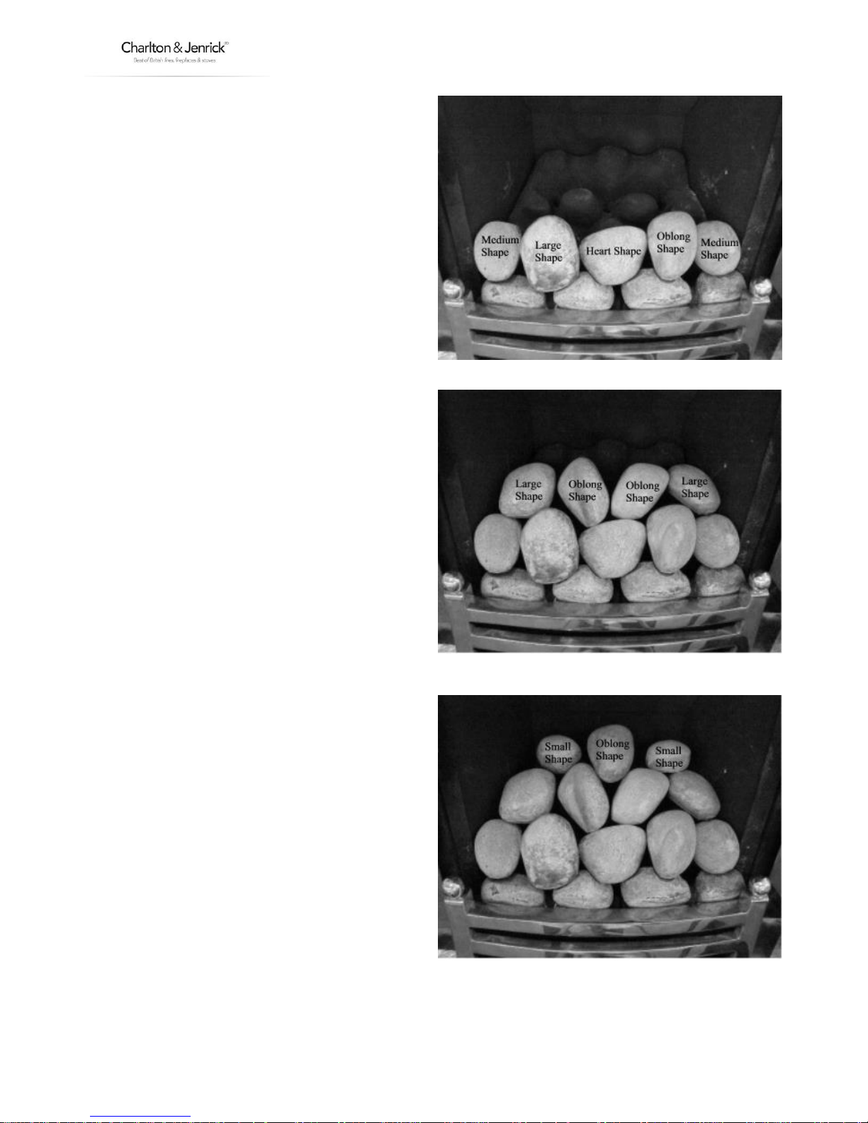
Locate the LEFT HAND and RIGHT HAND FRONT
PEBBLES as shown so that they sit on the front rail and
lean back against the BASE MATRIX. Note it is most
important that they are located in their correct
positions. They are marked on the rear "L" for LEFT
HAND FRONT PEBBLE and "R" for RIGHT HAND FRONT
PEBBLE.
Pebble
identification
QTY
Heart shape
1
Oblong shape
4
Large shape
3
Medium shape
2
Small shape
2
Total
12
14 LT5052 (ISS 5)
Lay one row of pebbles at the front of the fire as
shown.
Lay another row of loose pebbles shown.
Lay another row of loose pebbles as shown.
 Loading...