

Page 1

JetFusion
Integrated Access Device
Models 2004, 2008, 2104, and 2108
User’s Guide
Document No. 2000-A2-GB22-00
June 2004
Page 2

Copyright © 2004 Paradyne Corporation.
All rights reserved.
Printed in U.S.A.
Notice
This publication is protected by federal copyright law. No part of this publication may be copied or distributed,
transmitted, transcribed, stored in a retrieval system, or translated into any human or computer language in any form or
by any means, electronic, mechanical, magnetic, manual or otherwise, or disclosed to third parties without the express
written permission of Paradyne Corporation, 8545 126th Ave. N., Largo, FL 33773.
Paradyne Corporation makes no representation or warranties with respect to the contents hereof and specifically
disclaims any implied warranties of merchantability or fitness for a particular purpose. Further, Paradyne Corporation
reserves the right to revise this publication and to make changes from time to time in the contents hereof without
obligation of Paradyne Corporation to notify any person of such revision or changes.
Changes and enhancements to the product and to the information herein will be documented and issued as a new
release to this manual.
Warranty, Sales, Service, and Training Information
Contact your local sales representative, service representative, or distributor directly for any help needed. For
additional information concerning warranty, sales, service, repair, installation, documentation, training, distributor
locations, or Paradyne worldwide office locations, use one of the following methods:
Internet: Visit the Paradyne World Wide Web site at www.paradyne.com. (Be sure to register your warranty at
www.paradyne.com/warranty.)
Telephone: Call our automated system to receive current information by fax or to speak with a company
representative.
— Within the U.S.A., call 1-800-870-2221
— Outside the U.S.A., call 1-727-530-2340
This product has a one-year limited warranty.
Document Feedback
We welcome your comments and suggestions about this document. Please mail them to Technical Publications,
Paradyne Corporation, 8545 126th Ave. N., Largo, FL 33773, or send e-mail to userdoc@paradyne.com. Include the
number and title of this document in your correspondence. Please include your name and phone number if you are
willing to provide additional clarification.
Trademarks
ACCULINK, COMSPHERE, ETC, EtherLoop, FrameSaver, GranDSLAM, Hotwire, the Hotwire logo, Jetstream, MVL,
NextEDGE, OpenLane, Paradyne, the Paradyne logo, Paradyne Credit Corp., the Paradyne Credit Corp. logo,
Performance Wizard, StormPort, and TruePut are all registered trademarks of Paradyne Corporation. ADSL/R,
BitStorm, Connect to Success, GrandVIEW, Hotwire Connected, iMarc, JetFusion, JetVision, MicroBurst,
PacketSurfer, ReachDSL, Spectrum Manager, StormTracker, and TriplePlay are trademarks of Paradyne Corporation.
All other products and services mentioned herein are the trademarks, service marks, registered trademarks, or
registered service marks of their respective owners.
A 2000-A2-GB22-00
Page 3

FCC Requirements This equipment has been tested and found to comply with the limits for a Class A digital device
pursuant to Part 15 of the FCC Rules. These limits are designed to provide reasonable protection
against harmful interference when the equipment is operated in a commercial environment.
Operation of this equipment in a residential area is likely to cause harmful interference, in which
case the user is required to correct the interference at the user’s own expense.
This equipment generates, uses, and can radiate radio frequency energy, and, if not installed and
used in accordance with the instruction manual, may cause harmful interference to radio communications. However, there is no guarantee that interference will not occur in a particular
installation. If this equipment does cause harmful interference to radio or television reception
(which can be determined by turning the equipment off and on), the user is encouraged to try to
correct the interference by taking one or more of the following measures:
• Reorient or relocate the receiving antenna
• Increase the separation between the equipment and receiver
• Plug the equipment into an outlet on a circuit different from that to which the receiver is currently connected
• Consult the dealer or an experienced radio/TV technician for help
This device must also accept any interference received, including interference that may cause
undesired operation.
WARNING: JetFusion 2004, 2008, 2104, and 2108 are to be used only with a certified
Class 2 power supply. See Appendix B, Specifications.
WARNING: Changes or modifications to this unit not expressly approved by the party
responsible for compliance could void the user’s authority to operate the
equipment.
The JetFusion 2x04 and 2x08 comply with Part 68 of the FCC Rules and the requirements
adopted by the ACTA. On the bottom of the JetFusion unit is a label that contains, among other
information, a product identifier in the format of US:GICDDNANNE2x08. If requested, this
number must be provided to the telephone company.
1 All direct connections to network lines must be made using standard plugs and jacks
(compliant with Part 68 and the requirements adopted by the ACTA). A compliant telephone
cord with a modular plug is provided with this product. It is designed to be connected to a
compatible modular jack that is also compliant. See installation instructions for details. The
table below presents a list of applicable registration jack USOCs and facility interface codes
(FIC). These are required when ordering service from the telco.
IAD Port ID REN/SOC FIC USOC
2004/2008 ADSL 0.0B RJ11C
2104/2108 SHDSL 0.0B RJ11C
2 If the unit appears to be malfunctioning, it should be disconnected from the network lines
until the source of trouble is determined to be your equipment or the telephone line. If your
equipment needs repair, it should not be reconnected until it is repaired.
3 If your telephone equipment causes harm to the telephone network, the telephone company
may discontinue your service temporarily. If possible, they will notify you in advance.
However, if advance notice is not practical, you will be notified as soon as possible. You will
be informed of your right to file a complaint with the FCC.
4 Your telephone company may make changes to its facilities, equipment, operations, or
procedures that could affect the proper functioning of your equipment. If they do, you will
be notified in advance so you can have the opportunity to maintain uninterrupted telephone
service.
5 If you experience trouble with the JetFusion 200x or 210x unit, please contact your service
provider for information on obtaining service or repairs. The telephone company may ask
B
Page 4

that you disconnect this equipment from the network until the problem has been corrected or
until you are sure the equipment is not malfunctioning. No user serviceable parts are
contained in this equipment. This equipment may not be used for coin service provided by
the telephone company. Connection to party lines is subject to state tariffs. Contact the state
Public Utilities Commission or Corporation for information. Do not attempt to repair this
equipment yourself.
Canadian Emissions
Requirements
This digital apparatus does not exceed the Class A limits for radio noise emissions from digital
apparatus set out in the Radio Interference Regulations of the Canadian Department of Communications.
Le présent appareil numérique n’émet pas de bruits radioélectriques dépassant les limites applicables aux appareils numériques (de la class A) prescrites dans le Règlement sur le brouillage
radioélectrique edicté par le ministère des Communications du Canada.
Safety Precautions When handling this equipment, follow these basic safety precautions to reduce the risk of elec-
tric shock and injury:
• Follow all warnings and instructions marked on the product and in the manual.
• Unplug the hardware from the wall outlet before cleaning. Do not use liquid cleaners or aerosol cleaners. Use a slightly damp cloth for cleaning.
• Do not place this product on an unstable cart, stand, or table. It may fall, causing serious damage to
the product.
• Slots in the unit are provided for ventil ation to protect it from overheating. Thes e openings must not
be blocked or covered. Never place this product near a radiator or heat register.
• This product should be operated onl y from the type of power source indicated on the marking label
and manual. If you are unsure of the type of power supply you are u sing, consult your dealer or local
power company.
• Do not allow anything to rest on the power cord. Do not locate this product where the cord interferes
with the free movement of people.
• Do not overload wall outlets and extension cords, as this can result in fire or electric shock.
• Never push objects of any kind into the unit. They may touch dangerous vol tage points or short out
parts that could result in fire or electric shock. Never spill liquid of any kind on this equipment.
• Unplug the equipment from the wall outlet and refer servicing to qualified service personnel under the
following conditions:
• When the power supply cord or plug is damaged or frayed
• If liquid has been spilled into the product
• If the product has been exposed to rain or water
• If the product has been dropped or if the housing has been damaged
• To reduce the risk of electrical shock, do not remove th e cover from the un it or external p ower supply.
There are no user-serviceable parts inside this unit. Contact qualifified Paradyne service personnel.
C 2000-A2-GB22-00
Page 5

Table of Contents
About this Manual ........................................................ ..... .................................................................xiii
Manual Organization ....................................................................................................................xiii
Technical Documentation ............................................................................................................ xiv
Typographic Conventions ............................................................................................................ xiv
Chapter 1 Introduction
Interfaces and Features of the JetFusion IADs ................................................................................... 1-2
Platform Architecture ................................................................................................................... 1-2
Features ........................................................................................................................................ 1-2
Front Panel LED Status Indicators ........................................................................................1-3
Rear Panel Connectors ................................................................ ..... ......................................1-4
Chapter 2 Quick Start Guide
Unpacking the IAD ............................................................................................................................. 2-1
Installing the IAD ................................................................................ .... ..... ......................................2-2
AC Power and Uninterruptible Power Supply ............................................................................. 2-2
Clearance Requirements ...............................................................................................................2-2
Wiring Requirements ...................................................................................................................2-2
Connecting the IAD Via a Terminal Emulator ............................................................................ 2-2
Connecting the IAD to a PC .................................................................................................. 2-3
Logging in via a Terminal Emulation Program ..................................................................... 2-4
Setting the Ethernet Port IP Address ............................................................................................2-6
Setting the WAN Port IP Address ................................................................................................2-8
Resetting the IAD ................................................................................... ......................................2-8
Connecting via Telnet ..................................................................................................................2-9
Running Telnet ......................................................................................................................2-9
Basic IAD Configuration ......................................................... ..... .... .........................................2-11
Connecting LAN, WAN, and Telephones .................................................................................2-11
Ethernet LAN Connection ................................................................................................... 2-12
WAN Connections ...............................................................................................................2-12
Telephone Connections ....................................................................................................... 2-12
Life Line Connection ...........................................................................................................2-12
Confirming Proper Setup ...........................................................................................................2-12
Chapter 3 Administration
IAD Security .......................................................................................................................................3-1
Password Configuration Menu .....................................................................................................3-2
Change User ID .....................................................................................................................3-3
Change User Password ..........................................................................................................3-4
RADIUS Server Settings ....................................................................................................... 3-4
Setting Up SNMP ...............................................................................................................................3-5
i
Page 6

SNMP Configuration Menu .........................................................................................................3-6
Enable/Disable SNMP via IP ................................................................................................ 3-6
Enable/Disable SNMP via EOC ............................................................................................ 3-7
Enable SNMP via Both IP and EOC ..................................................................................... 3-7
Disable SNMP via Both IP and EOC ....................................................................................3-7
Configure System Contact ..................................................................................................... 3-7
Configure System Name ........................................................................................................ 3-8
Configure System Location ................................................................................................... 3-8
Configure SNMP Community ............................................................................................... 3-8
Configure SNMP Trap Host IP Address ...............................................................................3-8
Enable/Disable SNMP Traps via EOC .................................................................................. 3-9
Configure Restart Trap Maximum Delay .............................................................................. 3-9
Defining Different SNMP Version 3 Categories ...................................................................3-9
LAN Configuration Menu ................................................................................................................3-11
Establishing LAN Speed and Duplex Mode ..............................................................................3-11
Upgrading the System .......................................................................................................................3-12
Using TFTP Servers via LAN or WAN ..................................................................................... 3-12
Copying the Source Files ...........................................................................................................3-12
Upgrading via TFTP ..................................................................................................................3-12
Verifying the Upgrade ................................................................................................................3-13
Utilities Menu ................................................................................................................................... 3-13
Ping Utility .................................................................................................................................3-14
Trace Route ................................................................................................................................3-15
Configure Console Baud Rate ....................................................................................................3-15
Configure Console Timeout .......................................................................................................3-15
Reset or Reload ACOS from FLASH .......................................................................... .............. 3-16
Set System Default .....................................................................................................................3-16
Save System Settings as Defaults ..............................................................................................3-16
Display Event Log ......................................................................................................................3-17
Clear “Last Reset Reason” .........................................................................................................3-17
Time Zone Menu ........................................................................................................................3-18
File System Menu ......................................................................................................................3-18
Directory of all Files ................................................................................................... .... ..... 3-18
Copy File ..................................................... .... ....................................................................3-18
Rename File .........................................................................................................................3-19
Delete File ............................................................................................................................3-19
Format File System Drive ....................................................... .............................................3-19
Space Left in File System ....................................................................................................3-20
Debug Menu ...............................................................................................................................3-20
File Transfer Menu .....................................................................................................................3-20
Load Boot ROM ..................................................................................................................3-20
Update ACOS [acos.bin] .....................................................................................................3-21
Update Entire System ...................................................................... ....................................3-21
File Transfer Utilities ...........................................................................................................3-21
TFTP Server Menu ..............................................................................................................3-22
ii 2000-A2-GB22-00
Page 7

Chapter 4 Configuration
Introduction ......................................................................................................................................... 4-1
Managing Configuration Files ............................................................................................................4-1
WAN Configuration ........................................................................................................................... 4-2
Basic WAN Setup Tasks ........................................................................ .... ..................................4-2
Setting the WAN Port IP Address ................................................................................................4-3
Identifying the WAN Interface and Datalink Protocol ................................................................ 4-3
WAN Configuration Menu ..........................................................................................................4-4
Configure Physical Interface - G.SHDSL Interface (2104 and 2108 Only) ..........................4-5
Configure Physical Interface - ADSL Interface (2004 and 2008 Only) ................................ 4-6
Configure ATM PVCs ........................................................................................................... 4-7
Configure ATM Options .....................................................................................................4-12
Router Configuration ........................................................................................................................4-14
Basic Router Setup Tasks ...........................................................................................................4-14
Router Configuration Menu .......................................................................................................4-15
Configure Port IP Address ................................................................................................... 4-16
Unconfigure Port IP Address ............................................................................................... 4-17
Configure Port Maximum Transmission Unit (MTU) ........................................................4-18
Add/Remove a Static Route ................................................................................................ 4-18
Configure RIP Version by Port ...........................................................................................4-20
Configure RIP Poisoned Reverse by Port ............................................................................ 4-20
Configure DNS Client .........................................................................................................4-21
Configure DHCP Client .......................................................................................................4-22
Configure DHCP Relay ....................................................................................................... 4-22
Configure Telnet Server Port ............................................................................................... 4-24
Configure IP QoS ................................................................................................................4-24
Configure IP Filtering ..........................................................................................................4-25
Configure IP Header Compression (IPHC) .........................................................................4-26
Configure LAN IP Broadcast Destination ...........................................................................4-27
Display Route Table ............................................................................................................4-27
Bridge Configuration ........................................................................................................................4-27
Basic Bridge Setup Tasks ...........................................................................................................4-28
Bridge Configuration Menu .......................................................................................................4-29
Enabling and Disabling Bridging ........................................................................................ 4-30
IP Over Bridging ................................................................................. ..... ...........................4-30
Enable/Disable Bridging Globally .......................................................................................4-31
Enable/Disable Bridging by Port .........................................................................................4-31
Bridge Aging Timer .............................................................................................................4-32
Enabling and Disabling Spanning Tree ...............................................................................4-32
Enable/Disable Spanning Tree Globally ............................................................................. 4-32
Enable/Disable Spanning Tree by Port ................................................................................4-33
Configure Spanning Tree Bridge Priority ...........................................................................4-33
Configure Spanning Tree Port Priority ................................................................................ 4-33
Configure Spanning Tree Hello Time .................................................................................4-34
Configure Spanning Tree Maximum Age ...........................................................................4-34
Configure Spanning Tree Forward Delay ...........................................................................4-34
Configure Spanning Tree Path Cost ....................................................................................4-35
Delete Bridge Forwarding Database Entry ..........................................................................4-35
iii
Page 8

Voice Path Configuration .................................................................................................................4-35
Basic Voice Path Setup Tasks .................................................................................................... 4-36
Voice Configuration Menu ........................................................................................................4-36
Set Voice Gateway ..............................................................................................................4-36
Debug Control .....................................................................................................................4-40
Statistics ............................................................................................................................... 4-40
Set Jitter Delay .....................................................................................................................4-52
Voice Port Settings ..............................................................................................................4-52
Display Compander Mode (µ-law, A-law) .......................................................................... 4-57
Set Country Mode ................................................................................................................4-57
Set DuSLIC Mode ...............................................................................................................4-57
Firewall Configuration ......................................................................................................................4-58
Creating a Firewall via IP Filtering and NAT ............................................................................4-58
DHCP Server Configuration ............................................................................................................. 4-59
Basic DHCP Server Setup Tasks ............................................................... ................................4-59
DHCP Server Configuration Menu ............................................................................................ 4-59
Enable/Disable DHCP Server ..............................................................................................4-60
Enable/Disable Checking Additional DHCP Servers ..........................................................4-60
Enable/Disable DHCP Debug Messages .............................................................................4-60
Configure DHCP Server Parameters ...................................................................................4-60
Configure DHCP Address Range Pool ................................................................................ 4-61
Configure DHCP Client Entry ............................................................................................. 4-61
Display DHCP Configuration .............................................................................................. 4-62
Display DHCP Server Statistics .......................................................................................... 4-63
Display DHCP Server Assigned and Unassigned Addresses .............................................. 4-63
Display DHCP Entry Details ...............................................................................................4-64
Delete a DHCP Client Entry ................................................................................................ 4-64
Delete a DHCP Assignment Entry ......................................................................................4-64
Multicast Configuration .................................................................................................................... 4-65
Multicast Configuration Menu ...................................................................................................4-65
Enable/Disable Global IP Multicasting ...............................................................................4-65
Configure PIM - Dense Mode by Port .................................................................................4-66
Add/Change Multicast Route Source .................................................................................. 4-66
Show IGMP Group ..............................................................................................................4-67
Show IGMP Querier ............................................................................................................4-68
Show Multicast Routing Table ............................................................................................ 4-68
Show PIM Neighbor ............................................................................................................4-69
NAT Configuration ...........................................................................................................................4-69
NAT Configuration Menu ......................................................................................................... 4-70
Enable/Disable NAT Translation by Port ............................................................................4-71
Configure NAT TCP and UDP Timeouts ............................................................................4-71
Configure NAT Port Range .................................................................................................4-71
Configure NAT Local Server Entry ....................................................................................4-72
Configure NAT Alias Entry ................................................................................................4-73
Display NAT Statistics ........................................................................................................4-74
Display NAT Connection Table ................................................. .........................................4-75
Display NAT Connection Details ........................................................................................4-75
Display NAT Local Server Table ........................................................................................4-76
Display NAT Alias Table .................................................................................................... 4-76
iv 2000-A2-GB22-00
Page 9

Delete IP Address from NAT Tables .................................................................................. 4-76
Delete NAT Local Server Entry ..........................................................................................4-77
Delete NAT Alias Entry ...................................................................................................... 4-77
Setting Derived Timing Options .......................................................................................................4-77
Derived Timing Menu ....................................................................................................... ......... 4-77
Enable/Disable Derived Timing .......................................................................................... 4-78
Enable/Disable Derived Timing Debug Messages ..............................................................4-78
Chapter 5 Reports
Reports Menu ......................................................................................................................................5-1
Current Configuration Report ......................................................................................................5-2
Network Statistics Reports ......................................................................... ..................................5-4
ICMP Statistics Report ..........................................................................................................5-5
IGMP Statistics Report ............................................................................. .... ..... .................... 5-6
IP Statistics Report ........................................................ .... ..... ...............................................5-7
PIM Statistics Report .............................................................................................................5-9
TCP Statistics Report ...........................................................................................................5-10
UDP Statistics Report ..........................................................................................................5-11
Clear Network Statistics ......................................................................................................5-12
Interface Statistics Reports .........................................................................................................5-12
Display Interface Statistics ..................................................................................................5-13
Display ATM PVC Statistics ............................................................................................... 5-14
Display Bridge Statistics .....................................................................................................5-19
Clear Interface Statistics ......................................................................................................5-20
Media Statistics Reports .............................................................................................................5-20
Clear Media Statistics ..........................................................................................................5-25
Route Table Report ....................................................................................................................5-26
ARP Table Report ......................................................................................................................5-26
Bridge Forwarding Database Report .......................................................................................... 5-26
Bridge Status Report ..................................................................................................................5-27
PPP Authorization Entries Report .............................................................................................. 5-27
System Uptime Report ...............................................................................................................5-28
Memory Statistics Reports .........................................................................................................5-28
Display System Memory Statistics ......................................................................................5-28
Display Kernel Tasks Memory Statistics ............................................................................5-29
Zero All Statistics .......................................................................... .... ..... ....................................5-30
Chapter 6 Command Line Interface
Introduction ......................................................................................................................................... 6-1
CLI Help ....................................................................................................................................... 6-1
Chapter 7 Troubleshooting and Diagnostics
Using the Diagnostics Menu ...............................................................................................................7-1
POTS Diagnostics ........................................................................................................................7-1
Dialup Test ...........................................................................................................................7-2
v
Page 10

Hotline Test ........................................................................................................................... 7-2
Ring Test ............................................................................................................................... 7-3
Ring Test ................................................................................................................................ 7-3
On/Off Hook Test ....................................................................... ..... ......................................7-4
Troubleshooting the IAD ....................................................................................................................7-4
Chapter 8 Verification
Power-up Test .....................................................................................................................................8-1
Operational Test .................................................................................................................................. 8-1
Testing the IAD ............................................................................................................................8-2
Maintenance ................................................................................................................................. 8-2
Displaying the Current Configuration .......................................................................................... 8-2
Appendix A Menu Map
Appendix B Specifications
ADSL (2004, 2004s, 2008, and 2008s) ............................................... .... ..... ......................................B-1
Voice Features ..............................................................................................................................B-1
Analog Voice .........................................................................................................................B-1
Digital Voice ..........................................................................................................................B-1
Data Features ................................................................................. ...............................................B-2
WAN Features ..............................................................................................................................B-2
Interface .................................................................................................................................B-2
ATM ......................................................................................................................................B-2
Configuration and Management ...................................................................................................B-3
10/100 Ethernet (Management or IP Gateway) .....................................................................B-3
Supervisory Port ....................................................................................................................B-3
Upgrades ................................................................................................................................B-3
Management ..........................................................................................................................B-3
Security Features ..........................................................................................................................B-3
Integrated Firewall .................................................................................................................B-3
Management Interfaces ................................................................................................................B-3
Alarms ...................................................................................................................................B-3
Environmental ..............................................................................................................................B-4
Connector Pin Assignments .........................................................................................................B-5
DB-9 Console Port Pin Assignments .....................................................................................B-5
RJ11 POTS Port Pin Assignments .........................................................................................B-5
10BaseT Connector Pin Assignments (RJ45) .......................................................................B-5
100BaseT Connector Pin Assignments (RJ48) — ADSL .....................................................B-5
G.SHDSL (2104, 2104s, 2108, and 2108s) ........................................................................................B-6
Voice Features ..............................................................................................................................B-6
Analog Voice .........................................................................................................................B-6
Digital Voice ..........................................................................................................................B-6
Data Features ................................................................................. ...............................................B-6
vi 2000-A2-GB22-00
Page 11

WAN Features ..............................................................................................................................B-7
Interface .................................................................................................................................B-7
ATM .............................................................................................................................................B-7
Configuration and Management ...................................................................................................B-7
10/100 Ethernet (Management or IP Gateway) .....................................................................B-7
Supervisory Port ....................................................................................................................B-8
Upgrades ................................................................................................................................B-8
Management ..........................................................................................................................B-8
Security Features ..........................................................................................................................B-8
Integrated Firewall .................................................................................................................B-8
Management Interfaces ................................................................................................................B-8
Alarms ...................................................................................................................................B-8
Environmental ..............................................................................................................................B-8
Connector Pin Assignments .......................................................................................................B-10
DB-9 Console Port Pin Assignments ...................................................................................B-10
RJ11 POTS Port Pin Assignments .......................................................................................B-10
10BaseT Connector Pin Assignments (RJ45) .....................................................................B-10
100BaseT Connector Pin Assignments (RJ45) — SHDSL .................................................B-10
Assignments (RJ11) .............................................................................................................B-10
Appendix C Application Notes
Peak Cell Rate (PCR) Considerations and Recommendations ...........................................................C-1
Voice-only Applications ...................................................... ........................................................C-1
Voice and Data Applications .......................................................................................................C-2
Network Address Translation (NAT) .................................................................................................C-2
Accessing the Internet from the LAN ..........................................................................................C-2
Configuring NAT Port Range ......................................................................................................C-2
Configuring NAT TCP Timeout ..................................................................................................C-2
Configuring NAT UDP Timeout .................................................................................................C-3
Accessing LAN Devices from the Internet ..................................................................................C-3
NAT Local Server Configuration ..........................................................................................C-3
NAT Alias Configuration ......................................................................................................C-3
IP Filtering ............................................................................................... ..... ......................................C-4
Information Policy .......................................................................................................................C-4
Filtering Interface .........................................................................................................................C-5
JetFusion IP Packet Filtering Syntax and Grammar ....................................................................C-6
Grammar ................................................................................................................................C-6
Filter Rules ............................................................................................................................C-7
Actions ...................................................................................................................................C-7
Options ...................................................................................................................................C-8
Matching Parameters .............................................................................................................C-8
Keep History ........................................................................................................................C-10
Examples .............................................................................................................................C-11
Dial Plan ...........................................................................................................................................C-11
vii
Page 12

viii 2000-A2-GB22-00
Page 13

About this Manual
This reference guide for the JetFusion™ 2004, 2008, 21 04, and 2108
describes IAD features and specifications, configuration, and cabling. It is
designed to be used as a reference regarding commands, interface ports,
configuration parameters, and other information specific to your IAD.
Manual Organization
The chapters and appendices in this manual are arranged for quick reference
when you need it. We recommend that you first read the Quick Start Guide
and then refer to the remaining chapters for more detailed information.
Appendices are designed to complement the main chapters.
• Chapter 1, "Introduction" – introduces the features of the JetFusion IADs,
including the hardware, indicators, and ports.
• Chapter 2, "Quick Start Guide" – describes the process of getting an IAD up
and running in a typical customer premises. This chapter is helpful if you’re
new to JetFusion IADs, because it lists each step, beginning with unpacking
the IAD. It also provides information about logging on, using the menu
interface, setting the IP address, basic configuration tasks, and restarting the
IAD. The subsequent chapters provide more detailed information.
P
REFACE
• Chapter 3, "Administration" – provides information about security,
configuring Simple Network Management Protocol (SNMP), upgrading
ACOS, system utilities, and other topics.
• Chapter 4, "Configuration" – details how to configure the JetFusion IAD for
physical connection to the network (ADSL and G.SHDSL, and ATM) as well
as router, bridge, voice path, firewall, DHCP, Multicast, and NAT
configuration.
• Chapter 5, "Reports" − describes the reports you can run.
• Chapter 6, "Command Line Interface" – describes how to enter and exit CLI
mode, and how to use each command in the command line interface. You
may use these commands instead of using the corresponding commands in
the menu interface.
xiii
Page 14
• Chapter 7, "Troubleshooting and Diagnostics" – shows you how to
troubleshoot and diagnose your configuration when abnormal symptoms
occur in the voice or computer network.
• Chapter 8, "Verification" − describes the steps you take to verify normal
operation once you’ve installed, connected, and configured your IAD. It also
covers maintenance and how to display the current configuration.
• Appendix A, "Menu Map" − provides a graphic view of your IAD’s menu
interface, illustrating its navigation and organization.
• Appendix B, “Specifications” − defines the specifications for the IADs. In
addition, this section provides ordering information and all the connector pin
assignments for the interfaces on the back of the IADs.
• Appendix C, “Applications Notes” − provides various applications details.
Technical Documentation
A master glossary of terms and acronyms used in Paradyne documents is
available online at www.paradyne.com. Select Support → Technical
Manuals → Technical Glossary.
This document is available online at www.paradyne.com. Select Support →
Technical Manuals → Jetstream Media GatewaySystems.
To order a paper copy of a Paradyne document, or to speak with a sales
representative, please call 1-727-530-2000.
Typographic Conventions
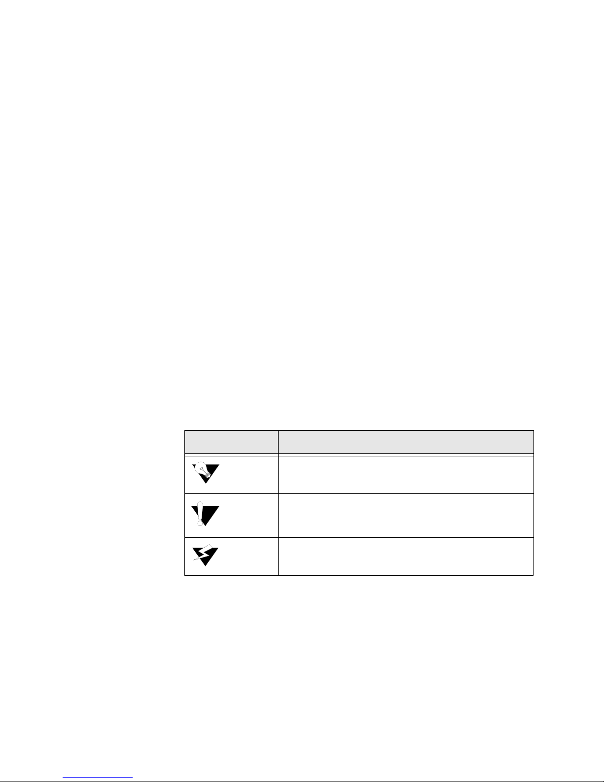
The following table lists the conventions used throughout this guide.
Convention Description
A Notice calls attentions to important features or instructions.
A Caution alerts you to serious risk of data loss or other
results that may cause you or the IAD trouble if the warning is
not heeded.
A Warning alerts you to the risk of serious damage to the IAD
or injury and possible death to the end user.
xiv 2000-A2-GB22-00
Page 15

C HAPTER
C
HAPTER
1
I
NTRODUCTION
This chapter introduces the JetFusion™ 2004, 2008, 2104, and 2108 integrated
access devices (IADs) and describes their hardware and software.
As competition in the telecommunications market intensifies, carriers find
themselves under growing pressure to reduce network costs and deliver
differentiated, highly competitive services. In response to this challenge,
Paradyne provides a family of IADs that incorporates the capabilities of
multiple networking devices capable of supporting ATM and multiple
applications such as the integration of voice/data and high-speed internet
access. By consolidating multiple network devices, converging multiple
services, and moving intelligence to the network’s edge, JetFusion IADs
lower requirements for capital equipment, minimize operational expenditures,
and maximize carriers’ profits. Using JetFusion IADs to integrate legacy
networks into evolving infrastructures, service providers can now also enable
budget-constrained customers to leverage the power of wide-area
communications for competitive advantage. In particular, these new services
allow SMBs, often lacking the resources to install and manage multiple
communications devices, to compete effectively with their larger counterparts
in the global marketplace.
The JetFusion IADs are access devices that terminate a DSL-based service,
and provide the end user with the ability to send and receive both voice calls
and data transmissions via a single connection. The connection may be either
ADSL or G.SHDSL. Models are equipped with up to eight voice ports and an
Ethernet interface with integrated routing protocols and functionality.
Two versions of these IADs are offered: a base version that provides support
for VoATM only and an “s” version that provides all the features of the base
model plus support for MGCP and SIP. The built-in flexibility of the
JetFusion IADs, supporting emerging protocols such as MGCP and SIP,
enables the IAD to evolve with the network, and provides an easily managed,
cost-effective migration to VoIP.
2104, or 2108 provides a single unit solution that can support VoATM and
VoIP applications in a single unit. This provides the user with CPE
investment protection, reduced inventory and training requirem ents, as well as
a built-in migration path from VoATM to VoIP by a simple reconfiguration of
the unit. No costly truck rolls or forklift upgrades are required.
The “s” version of the JetFusion 2004, 2008,
Introduction 1-1
Page 16

The JetFusion IADs are ideal for service providers offering small businesses
or home offices high-quality voice and data service over broadband circuits.
In addition to the up to eight POTS ports, this series includes complete LAN
support with a full range of integrated features, and offers toll-quality voice
and high-speed Internet access over a single copper pair in one unit. The
JetFusion IADs support any POTS device via a voice subsystem, and any
IP-based computer system (Ethernet printers; personal computers including
Windows, Macintosh, Unix, Linux, etc.; network file servers; and other
network devices) via a LAN subsystem.
Interfaces and Features of the JetFusion IADs
Platform Architecture
The JetFusion IADs are based on a single-board, fixed-conf iguration
architecture. Each unit supports 1 WAN interface (ADSL or G.SHDSL), 1
LAN interface, and 8 POTS interfaces. The eight-port units are housed in a
plastic enclosure with and external power supply.
All units are based on a common core design consisting of a Motorola Power
QUICC CPU, 16 or 8 Mbytes of dynamic memory, and 2 Mbytes of FLASH
memory. Voice packetization and processing are handled by Texas
Instruments Digital Signal Processors (DSP).
Features
The JetFusion IADs provide a highly interoperable, cost-effective voice and
high-speed data integration solution that is compatible with industry-leading
DSLAM and Voice Gateway manufacturers. These IADs prioritize voice
packets and dynamically allocate bandwidth between voice and data services.
Features include the following:
• For G.SHDSL, supports the following DSLAMs for ATM: Lucent, Nortel,
and Nokia
• Supports the following Voice Gateways: CopperCom, Paradyne (JetStream),
TdSoft, Broadsoft, MetaSwitch, Cirpack, NuERA Tollbridge, General
Bandwidth, Accelerated
• Provides seamless voice and high-speed data integration over G.SHDSL or
ADSL
• Supports data from POTS and 10/100BaseT customer premise interfaces
• Compatible with standards-based ATM WAN protocols
• Provides RJ11 POTS interface with Loop Start or Ground Start
• Provides dynamic and static IP routing and bridging capabilities
• Provides firewall support via IP filtering
• Offers DHCP and NAT to support IP address management
1-2 2000-A2-GB22-00
Page 17
• The “s” versions provide support for MGCP and SIP with the flexibility to
support VoATM/VoIP applications all in one unit
• Provides management capabilities including Telnet, SNMP, and TFTP
The JetFusion IADs are characterized by their different WAN interfaces:
• JetFusion 2004 and 2008 − provide voice services and WAN access via
ADSL.
• JetFusion 2104 and 2108 − provide voice services and high-speed Internet
or corporate connectivity over G.SHDSL.
Physical and electrical specifications for the IADs are listed in Appendix B,
Specifications.
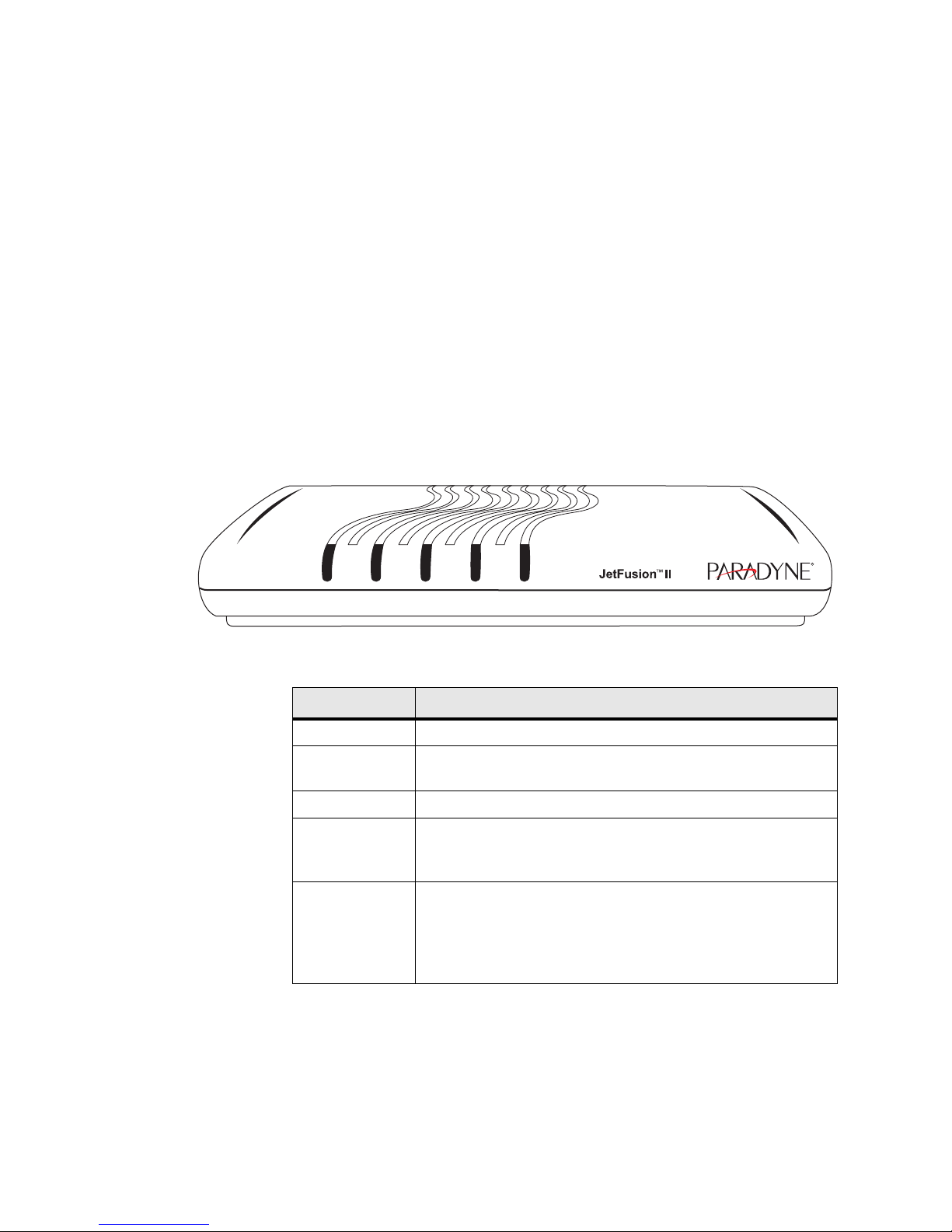
Front Panel LED Status Indicators
The IAD front panels contain five LED status indicators. Each is described in
the table below.
Figure 1.1
LED Description
POWER Illuminates when the IAD is powered on.
LAN LINK Illuminates when there is an operational LAN connection on the
LAN ACT Flashes when there is activity on the Ethernet port.
WAN LINK Flashes as the IAD is establishing a link, and illuminates solid
VOICE Illuminates when there is activity on the voice ports. When
Front Panel
LAN LINK LAN ACT WAN LINK VOICEPOWER
04-17479a
Ethernet port.
when there is a proper connection on the WAN port and
synchronization has been achieved.
connected to a CopperCom and Paradyne (Jetstream™) Voice
Gateway, it remains lit, and blinks when there is activity. (This
LED does not remain lit when other types of voice gateways are
connected, but will illuminate when a call is active.)
Introduction 1-3
Page 18
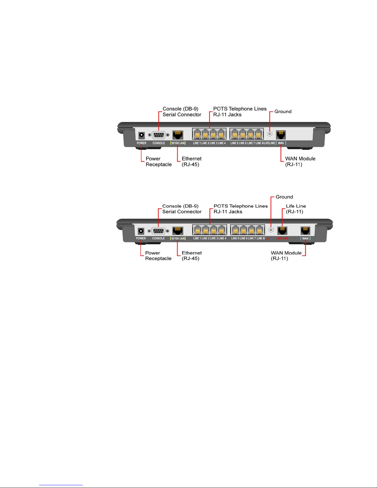
Rear Panel Connectors
The IAD rear panels have the following connectors: POWER, CONSOLE,
10/100 LAN, LIFE LINE, LINE 8-1 telephone connectors (LINE 1/LIFELINE, and
The 2104 and 2108 rear panel has an additional LIFE LINE connector.
WAN.
Each of these connectors is described below. Each unit has a
of which is illustrated in Figure 2.1.
Ground, the use
Figure 1.2
Figure 1.3
JetFusion 2008 Rear Panel Connectors
JetFusion 2108 Rear Panel Connectors
POWER (DC Power
Connects the IAD to any AC 90-240 V outlet.
Adapter)
Console (RS-232 Serial
Port)
Connects the IAD to a PC using a straight-through 9-pin serial (DB9 RS-232)
cable, for the purpose of using a terminal emulator for IAD configuration and
management.
10/100LAN
(10/100BaseT Ethernet
Port)
LINE 1-8 (Telephone
Connects the IAD to the local area network using a CAT-5 straight-through
Ethernet cable, or directly to a PC for accessing via Telnet (using a
cross-over, customer-supplied cable).
Supports eight analog telephones via RJ11 POTS ports.
Interfaces)
LIFE LINE
WAN
Provides access to a telephone line when there is no power to the IAD.
Connects through WAN interface as follows:
• JetFusion 2004 and 2008 − ADSL (uses an RJ11 connector for the
1-4 2000-A2-GB22-00
connection).
Page 19

• JetFusion 2104 and 2108 − G.SHDSL (uses an RJ11 connector for the
connection).
Data Interfaces
The data connection through the IAD supports IEEE 802.1-compliant bridging
and routing.
When the IAD is configured for routing, it supports Routing Information
Protocol (RIP) version 1, version 2, or static IP routing. The IAD complies
with RFC-1812 when interfacing with IPV4 routers. The WAN subsystem
supports the following interfaces: ATM data transport via G.SHDSL and
ADSL per RFC 1483 or RFC 2364
Introduction 1-5
Page 20

1-6 2000-A2-GB22-00
Page 21

C HAPTER
C
HAPTER
2
Q
UICK
This chapter describes the steps to install, connect, and set the IP address of
the JetFusion IAD. It introduces the menu interface and describes how to
perform basic configuration for common LAN and WAN environments. It
also describes basic operations such as resetting the IAD and logging off.
In many cases, all the information you need to get an IAD up and running is
included in this single chapter. In most installations, you will proceed through
these topics in order. If your situation varies, you will find more detailed
information on installation, connection, configuration, and troubleshooting in
the chapters that follow this Quick Start Guide.
S
TART
G
UIDE
Unpacking the IAD
Each IAD is packed and shipped in a durable container. Unpack and carefully
remove the IAD from the package and packing material.
IAD Package
Components
Each IAD is shipped with the components listed below. As you unpack them,
note their condition and identity and compare the list with the packing list in
the package.
• AC power adapter and cord (6 feet long), or AC power cord
• Agency Compliance information sheet
• Ethernet cable (straight through), 7 feet long
• WAN cable, 7 feet long
If you note any visible damage or missing components, notify the shipping
company immediately to make a damage claim. Contact the company from
which the IAD was purchased (Verilink, or an authorized distributor) to
obtain a Return Material Authorization (RMA) for return of damaged
equipment or to order missing components.
NOTICE: Consider keeping the shipping container and packing material for
future storage or shipping of the unit.
Quick Start Guide 2-1
Page 22

Installing the IAD
After you unpack the IAD, find a suitable location to install the unit. Ideal
locations include a computer equipment room or a telephone or wiring c loset.
You can locate the IAD on a table or shelf, or it may be wall-mounted. Install
the IAD in a location that is generally protected and where it will be
undisturbed.
AC Power and Uninterruptible Power Supply
The IAD requires access to AC power (NEMA 15-3R). Make sure the IAD is
located within 6 ft of an AC power outlet. Locate the nearest power outlet and
plug in the supplied AC power adapter or AC power cord. If there is an
uninterruptible power supply on premises, plug the AC power adapter or cord
into that power source.
Ensure the power cord conveniently and safely reaches the rear panel of the
IAD where the power plug or adapter jack is located.
Clearance Requirements
When you install the IAD horizontally, make sure you maintain at least 2
inches of horizontal distance from other IADs or other electronic equipment
to ensure adequate ventilation and heat dissipation.
NOTICE: Due to generated heat, JetFusion IADs should not be stacked on top of
each other.
Wiring Requirements
Make sure the telephone wiring, LAN, and WAN cables reac h the IAD and
can be dressed in a manner that is safe for the wiring, does not pull or create
lateral stress on the connectors or ports on the rear of the IAD, an d does not
present a trip hazard to personnel working in the vicinity of the equipment.
Do not connect any cables or wiring at this time.
Connecting the IAD Via a Terminal Emulator
The IAD is configured and managed from either the console or Ethe rnet port.
A Telnet session is usually used to access the IAD via Ethernet. After you use
a terminal emulator program via the console port (refer to DB-9 Console Port
Pin Assignments on page B-5) for console port specifications) to set the IP
address, you may continue to use a terminal emulator via the console port.
The factory-set default IP address is
NOTICE: After a period of inactivity (3 min by default), the IAD automatically
terminates console-based and Telnet sessions to maintain security. To
change this value, see Configure Console Timeout on page 3-15.
192.168.1.254 for the Ethernet port.
2-2 2000-A2-GB22-00
Page 23

Before you can connect to the IAD via Telnet, make sure the IP address is set
correctly for this network by following these steps:
• Connect the IAD to a PC
• Log in to the IAD
• Set the IP address
Each of these steps is described in detail below.
NOTICE: Ensure the IAD and PC are both powered OFF before connecting the
console cable. If both devices are not turned off when you connect the
cables, you may place the IAD in an unstable state, and you may need
to reset one or both devices before you can perform configuration tasks.
Connecting the IAD to a PC
To connect the IAD to a PC via the console port, follow the steps below.
1 Turn off both devices and insert the male connector of a DB9 serial cable
into the console port on the IAD.
2 Insert the female connector of the cable into a serial (COM) port on your
PC.
WARNING: For Ground Start applications, ensure the IAD is properly grounded. Refer to
Figure 2.1.
Quick Start Guide 2-3
Page 24
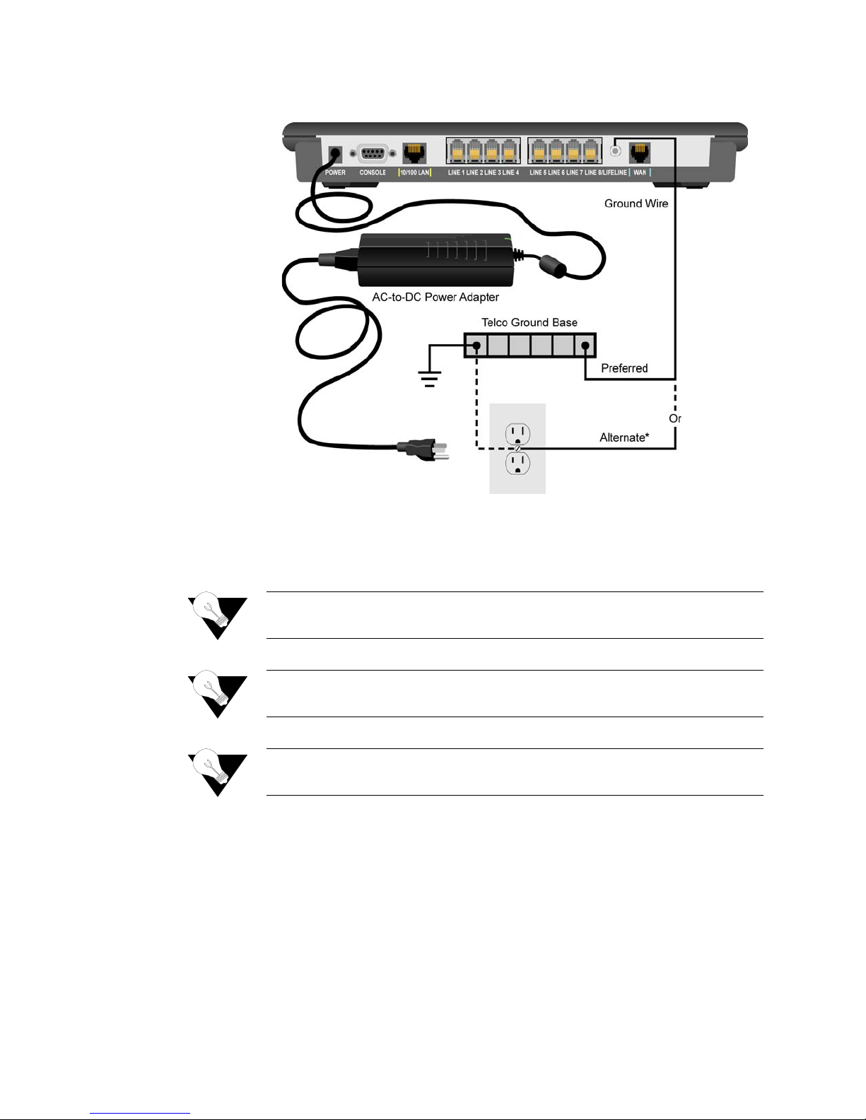
Figure 2.1
Grounding Diagram
3 With the console cable connected, plug the AC power adapter into the IAD.
This starts the IAD, and it executes the boot process to begin normal
operation. Verify that the Power indicator on the front panel illuminates.
NOTICE: For “cold start” access, the IAD default (factory-set) IP address is
192.168.1.254 on the Ethernet side.
NOTICE: For “Ground Start” applications, all elements i n the voice path must be
set to “Ground Start.”
NOTICE: As the IAD boots, it sends status messages to the console port. If you
are connected, you will see the boot sequence progress.
Logging in via a Terminal Emulation Program
With a serial cable connected, follow the steps below to log in to the IAD:
1 Open a terminal emulation program (Hyperterminal, for example).
2 Select the COM port to which the IAD is connected.
2-4 2000-A2-GB22-00
Page 25
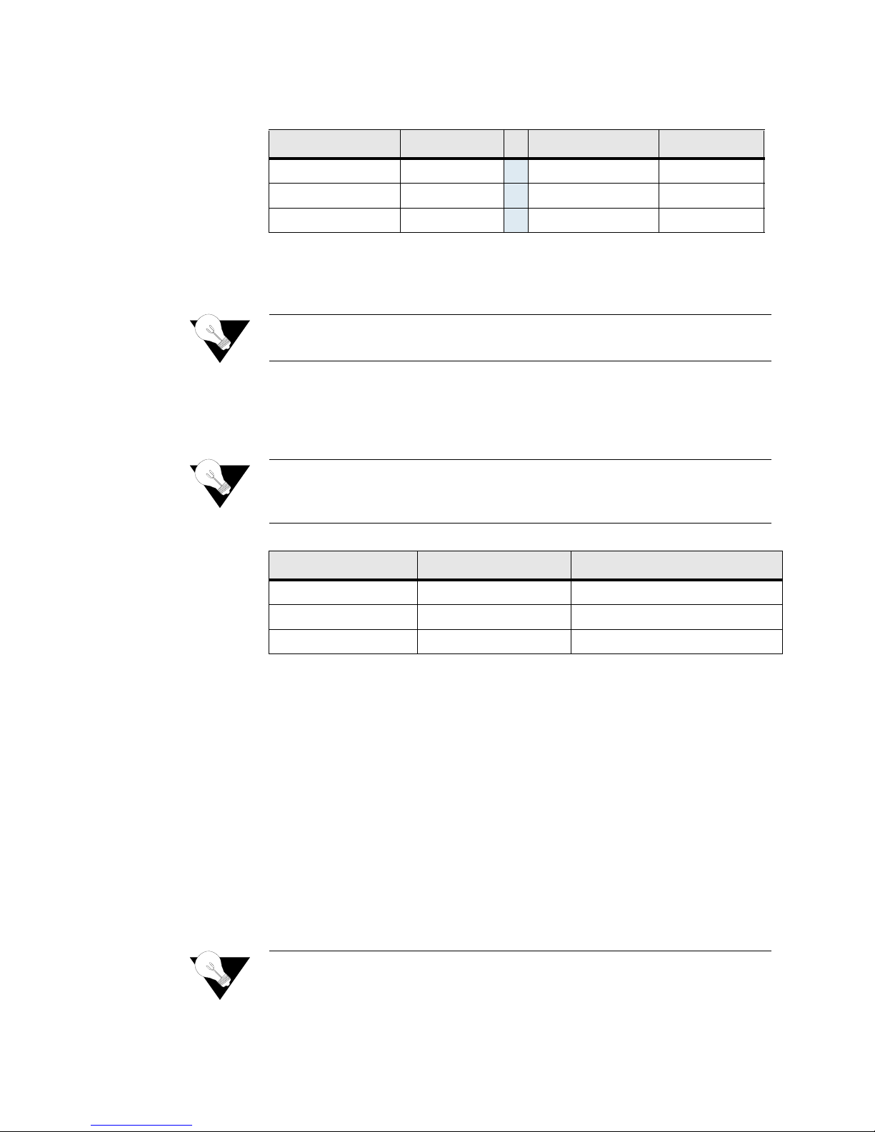
3 Type or select the settings described in the table below and save your
changes.
Setting Value Setting Value
Bits per second 19,200
Data bits 8
Parity None
Stop bits 1
Flow control None
Emulation ANSI or VT100
4 Press Enter. The IAD displays the login message:
5 Enter Login ID >
NOTICE: If the IAD does not respond, make sure the IAD is powered up, check
the cable and connections, and review the settings.
6 Type the default supervisor level user ID (Supervisor) (or your user ID,
if changed) and press Enter. Note that both the user ID and password are
case-sensitive. The table below lists the default user IDs and passwords.
NOTICE: Refer to Chapter 3, “Administration,” for detailed procedures regarding
all IAD administrative tasks. Follow these procedures after performing
the basic set-up functions described in this “Quick-Start Guide”.
Security Level User ID Password
User <Enter> <Enter>
Network Administrator NetMan <Enter>
Supervisor Supervisor supervisor
7 The IAD displays the password mes sage:
Enter Password >
8 Type the defa ult password (supervisor, or your password if different)
and press Enter. If login is not successful, the IAD displays the following
message:
Invalid UserID or Password - Try again
Press any key to continue...
9 Press any key, and repeat the login sequence. If you cannot log in, call your
support provider for assistance.
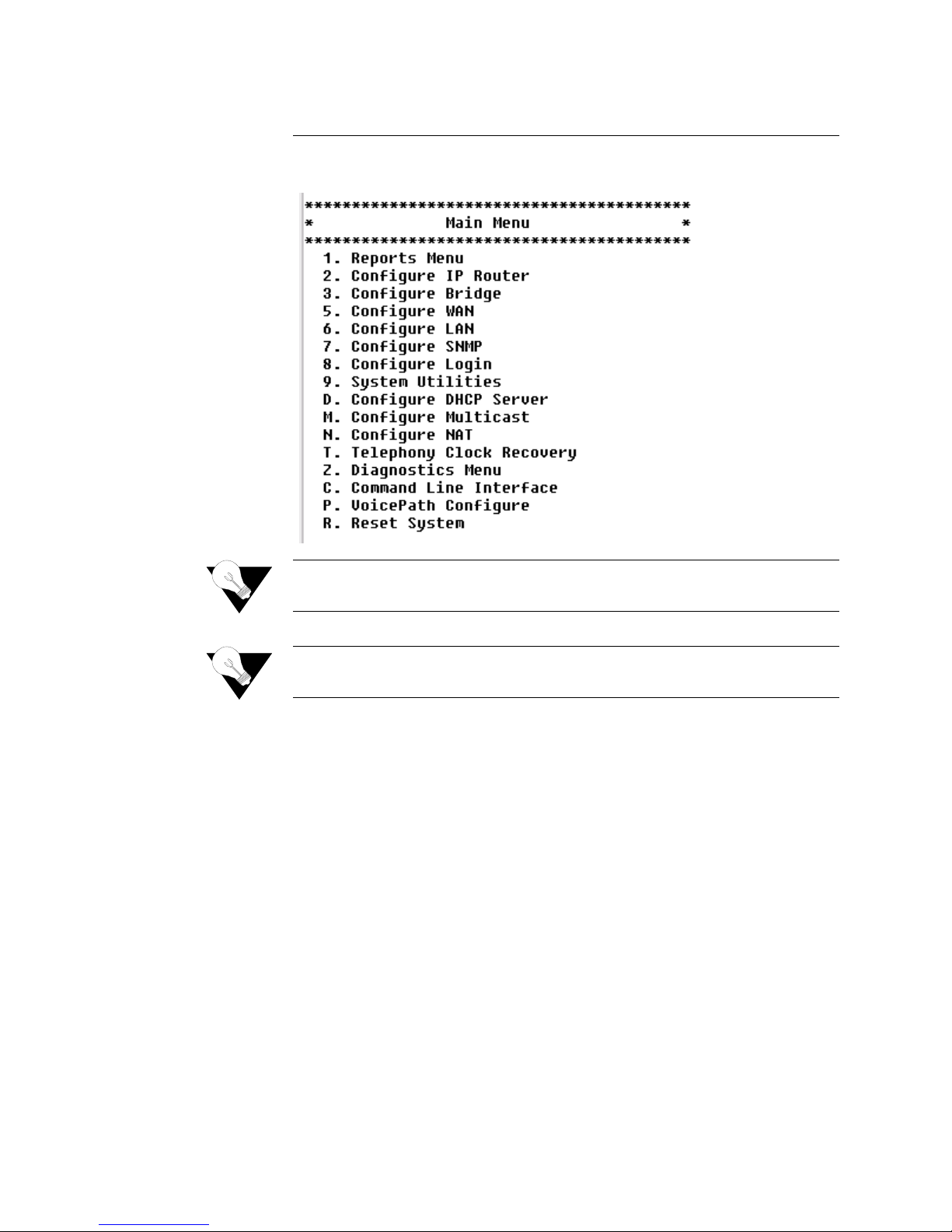
When you first log in, the IAD displays the Main menu (Figure 2.2). The
menu may vary, depending on the IAD.
NOTICE: If you are entering the menu to change a previously established
configuration, refer to Managing Configuration Files on page 4-1 t o
Quick Start Guide 2-5
Page 26
save the current configuration for fast restoration in case the new
configuration does not work.
Figure 2.2
Main Menu
NOTICE: Options vary depending on the voice gateway selected in the Voice Path
Configure command. Refer to Voice Configuration Menu on page 4-36.
NOTICE: When the IAD prompts you for input, the current value is displayed in
parentheses. To conveniently accept the current value, just press Enter.
Setting the Ethernet Port IP Address
Before you configure the Ethernet IP address, you should know the IP address
and subnet mask that are to be assigned to this port. They may be displayed
on the work order, or you may obtain or determine the appropriate IP address
by consulting with the network administrator.
The IAD is shipped with the IP address set to
subnet mask set to
the steps below.
1 On the Main menu, type “2.” The IAD displays the Router Configuration
menu (Figure 2.3).
255.255.255.0. To configure a port IP address, follow
192.168.1.254 and the
2-6 2000-A2-GB22-00
Page 27
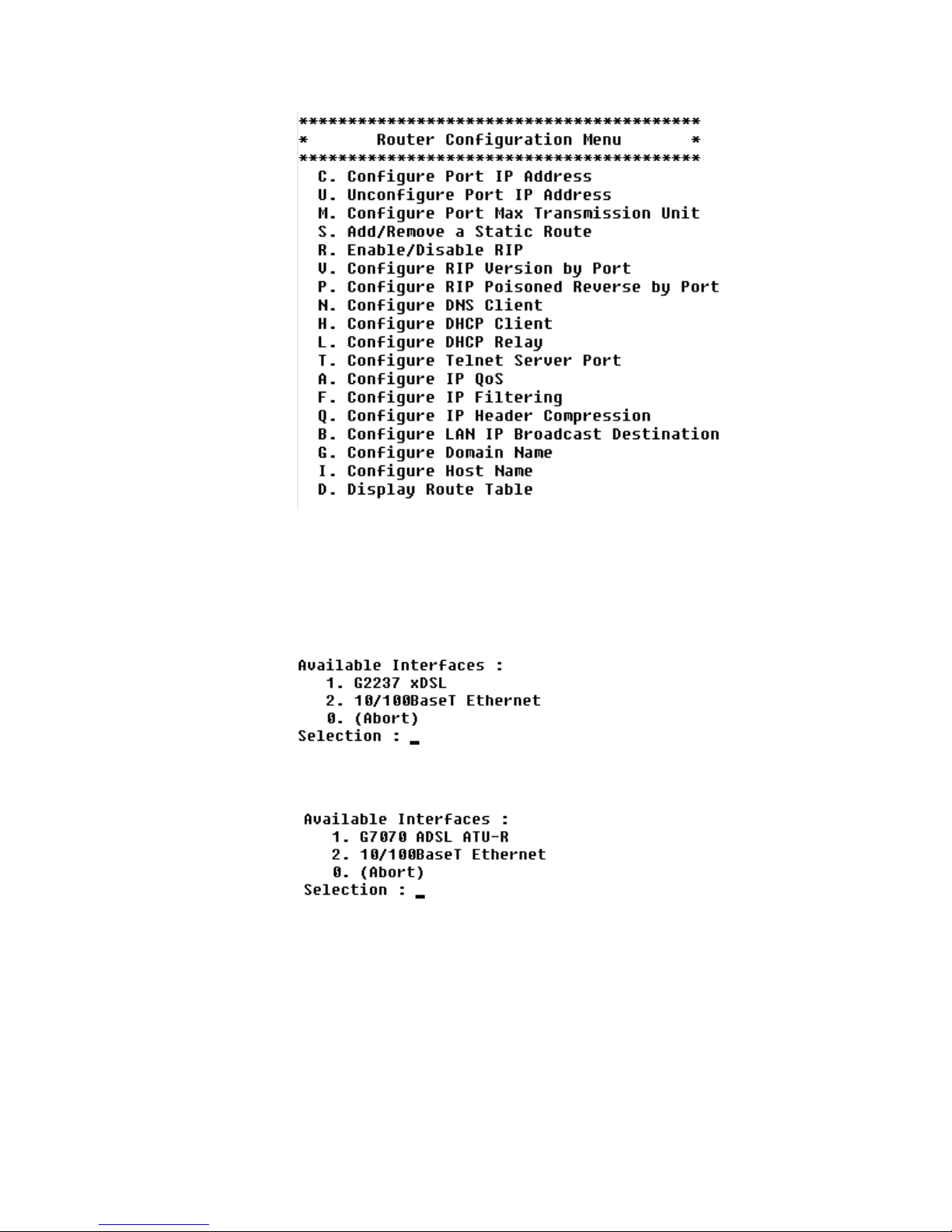
Figure 2.3
Router Configuration Menu
2 Type “C” to select Configure Port IP. The IAD displays the available
interfaces. The available interfaces that display depend on the specific IAD
as shown in Figure 2.4 and Figure 2.5 below.
Figure 2.4
Figure 2.5
JetFusion 2104 and 2108 Available Interfaces
JetFusion 2004 and 2008 Available Interfaces
Quick Start Guide 2-7
Page 28

3 Type “2” to set the IP address for the Ethernet port. If the IP address is
configured for the port, the IAD displays information about the interface
and a prompt such as that shown in the example below:
4 Type the ID number of the conne ction you want to configure (in this case,
“0”) and press Enter.
5 Type the new IP address, and press Enter (or press Enter to retain the
current IP address). The IAD displays the Current Subnet Mask and
prompts you for a new one.
6 Type the new Subnet Mask (usually 255.255.255.0) and press Enter. The
IAD prompts you to select High or Normal priority.
7 To give the interface normal priority, type “N” or press Enter.
8 Type “Y” or Enter to save the new IP address and subnet mask.
9 To exit, press Escape, and then type “Y” to terminate the session.
10 Quit the terminal emulator program.
11 Reset the IAD as described below (“Resetting the IAD”) for the new IP
address to be in effect.
NOTICE: When you configure the IAD, you must restart the IAD each time you
change the settings for those changes to take effect. You may make
several configuration changes before resetting.
If you plan to use Telnet for configuration tasks (Connecting via Telnet on
page 2-9), this is a good time to disconnect the serial cable from the PC and
IAD.
Setting the WAN Port IP Address
To set the WAN port IP address, follow the same procedures as those listed in
Setting the Ethernet Port IP Address on page 2-6.
Resetting the IAD
Many configuration tasks require that you reset (or restart) the IAD before the
new settings or configuration will take effect. When you use the menu
interface (or the Command Line Interface − Chapter 6, “Command Line
Interface”) to make changes, or change the physical characteristics of the IAD
(such as the Ethernet port MAC address), you must reset the IAD.
2-8 2000-A2-GB22-00
Page 29

The IAD stores all configuration settings in memory. When it restarts, it loads
the last configuration saved before it was powered down or restarted. When
restarting is required, it will be included as a step in the configuration process.
You can reset the IAD in one of the two following ways:
To reset the IAD from the menu:
1 On the Main menu, type “R” to select Reset System.
2 Type “R” again at the prompt. This resets and starts the IAD with your
new settings.
3 To log in again, enter your user ID and password.
To reset the IAD manually, unplug the power adapter from the IAD and then
plug it back in.
CAUTION: Be sure to complete your task and return to the Main menu before
Connecting via Telnet
restarting the IAD manually. Resetting the IAD terminates all
telephone calls and computer sessions in progress. You should ensure
there are no services being rendered before resetting the IAD.
To manage the IAD via the LAN (or Intranet), you must set an IP address for
the Ethernet port before you can use Telnet to access the IAD.
Although you can also access the IAD using Telnet via the WAN (provided a
management PVC is configured along with a WAN IP address), this section
describes connecting via the LAN. For information about setting the IP
address of the WAN port (Refer to Managing Configuration Files on
page 4-1.)
If you configure a RADIUS Client, you must use a RADIUS-authenticated
User ID/password for Telnet access. If the RADIUS server or the connection
to the RADIUS Client goes down, Telnet access will not be permitted. For
information about configuring a RADIUS client (Refer to RADIUS Server
Settings on page 3-4.)
Running Telnet
Before you use Telnet to log into the IAD, ensure the IAD and your PC are
connected to the same network via straight-through Ethernet cables (or
directly connected via a cross-over cable), and you know the IP address of the
IAD. Both devices must be on the same subnet.
To log in, follow the steps below.
1 Run Telnet on your PC.
2 Type the IP address of the Ethernet port (refer to Setting the Ethernet Port
IP Address on page 2-6), click Connect and then press Enter to gain the
attention of the IAD. The IAD responds by prompting you to enter your
Login ID.
Quick Start Guide 2-9
Page 30

3 Type your user ID and press Enter. The IAD will then prompt you to enter
your Password.
NOTICE: After a period of inactivity (three minutes by default), the IAD
automatically terminates console-based and Telnet sessions to maintain
security. To change this value, refer to Configure Console Timeout on
page 3-15.
NOTICE: Default user IDs and passwords are listed in the table on page 2-5. For
information on security levels, and user ID and password management
see IAD Security on page 3-1.
4 Type your password and press Enter to display the Main menu (Figure 2.2).
NOTICE: The user ID and password transmit as clear text, which may be
captured by unauthorized individuals. If you are concerned with
network security, you may not want to use Telnet to configure the IAD.
Navigating the IAD
Menu Interface
Entering Settings and
Values
Using Default or
Current Values
Menus in the IAD configuration system are arranged hierarchically. That is,
you select single-key options to navigate down to display specialized menus
and specific tasks, and press the Escape key successively to return back to
menus higher in the interface.
The specific menus, submenus, and commands that display depend on the
interfaces for the specific IAD, the options configured, and the security level
you use to log in.
To select a menu item, type the option displayed to the left of the item.
Although character options are displayed in upper case, the IAD accepts both
upper- and lower-case options. It is not necessary to press Enter after typing
the selection − the IAD immediately responds with a request for input or
another menu for more options.
For a hierarchical map of the Main menu, its menus and commands, see
Appendix A.
When the IAD requests input for a setting or configuration value, type it at
the prompt. Press the Enter key to terminate the input and proceed to the next
step. The IAD responds with error messages if a value is incorrect, or it
displays the current menu so you can continue with related tasks.
The IAD displays a default or current value in parentheses immediately to the
right of each message, just to the left of the command prompt. To accept this
value, press the Enter key.
For example, when the prompt asking you to enter a new Subnet mask
displays, you may press Enter to cause the IAD to set
Subnet Mask value. Using the Enter key to skip through default or current
values often speeds the process of proceed ing through a family of input steps
to more quickly reach the input step where you wish to change a value.
2-10 2000-A2-GB22-00
255.255.255.0 as the
Page 31

Exiting the Menu
Interface
To exit the menu interface, return to the Main menu using the Escape key,
and press Escape one more time. When the IAD asks you to confirm, press
“Y” to exit or press Return to accept the default value “N” to cancel the exit.
NOTICE: After exiting, you can quit the terminal emulator or Telnet session. If
Basic IAD Configuration
Each IAD is shipped with a default configuration set in the file default.st.
Once you make any changes to your IAD, a new file is created to store the
new configuration—config.st—to preserve the default settings.
After you have configured the IAD for correct operation in a customer’s
premises, the current system settings in the config.st file may be saved as the
default configuration file (custdef.st), and you may choose to set the IAD to
boot from this file each time it is reset. You may also copy this file to a PC or
TFTP server for downloading to other identically configured IADs. Once you
have replaced the original custdef.st file, you cannot retrieve it. Consider
copying the custdef.st file to a safe location before replacing it.
To perform basic IAD configuration, follow the steps below.
you made changes to the configuration that require resetting the IAD,
be sure to do so before exiting.
• Configure the LAN IP address, if not already completed (page 2-6).
• Configure each of the WAN options and the DSLAM profile (page 4-2 and
the pages following 4-1).
• Create and configure at least one PVC (page 4-7) for data traffic and set the
WAN IP address (page 2-6).
• Configure static or default route (page 4-14) or enable bridging (page 4-28)
for all data traffic.
• Create and configure a PVC (page 4-7) for voice where required, and select
appropriate voice gateway settings (page 4-36).
• Reset the IAD (page 2-8) to enable all configuration changes.
NOTICE: You must reset the IAD after configuring IP addresses before you may
add routes.
Connecting LAN, WAN, and Telephones
This section details how to connect the IAD to the computer and telephone
systems the IAD is intended to support.
Before proceeding, make sure you have an appropriate serial cable for your
PC, identify the LAN switching equipment where you’ll connect the IAD,
identify the telephone cables, and verify that WAN service is installed and
configured by the service provider.
When you’ve completed this section, reset the IAD so it can synchronize
these physical connections.
Quick Start Guide 2-11
Page 32

Ethernet LAN Connection
The Ethernet LAN port on the rear of the IAD is an RJ45 jack for
10/100BaseT Ethernet cables. If the IAD is intended to act as an Internet
gateway for the LAN in the customer’s premises, connect the IAD to the
switch, hub, or router using an Ethernet straight-through cable.
NOTICE: You may temporarily connect the IAD directly to a PC for Telnet
configuration (without going through a hub or router). The Ethernet
receiver automatically detects the type of Ethernet cable
(customer-supplied).
WAN Connections
WAN connections vary, based on the WAN interface on your IAD. The
JetFusion 2104 or 2108 is a G.SHDSL-equipped IAD and uses an RJ11
connector to connect to the rear panel WAN connection. To make the
connection, plug the G.SHDSL cable into the RJ11 WAN connector. The
JetFusion 2004 or 2008 is an ADSL-equipped IAD and uses an RJ11
connector on the IAD rear panel for WAN connectio n. To make the
connection, plug the cable from the ATM network into the RJ11 WAN
connector.
Telephone Connections
The IADs provide four or eight RJ11 ports for POTS devices. These devices
may be POTS telephones, modems, FAX machines, or other
POTS-compatible devices.
Life Line Connection
The 2104 and 2108 IAD have an RJ11 Life Line associated with POTS line 1.
The Life Line is an analog line that can be directly connected to the PSTN. In
the case of a power loss, POTS line 1 automatically switches to the Life Line
connection.
Confirming Proper Setup
When you have completed the tasks in this chapter, reset the IAD and test
your configuration for proper data and voice operation. Reset the IAD
(page 2-8) to synchronize the physical connections using the verification
procedure described in Chapter 8.
2-12 2000-A2-GB22-00
Page 33

C HAPTER
C
HAPTER
3
A
DMINISTRATION
This chapter describes how to control security to your IAD, validate users
using a RADIUS Server, configure SNMP via IP or AAL2 Embedded
Operations Channel (EOC), upgrade IAD software, and perform other general
and utility-oriented tasks.
NOTICE: When the IAD prompts you for input, the current value is displayed in
parentheses. To conveniently accept the current value, just press Enter.
IAD Security
NOTICE: After setting IAD Security parameters, you must reset the IAD
(page 2-8) for the new set tings to take effect.
To maintain IAD security, the IAD provides multi-level login access using a
single user ID and password, which you can set at the following levels:
• User
• Network Administrator
• Supervisor
The user ID at the User security level may be modified, but the user ID at the
Network Administrator and Supervisor levels may not.
The password for each security level may be changed. Although you may use
the same password for all security levels, for best security you should use a
different one for each level. The table below lists the privileges available at
each security level.
Administration 3-1
Page 34

Security level Privileges
Supervisor This user level is the highest level. Users who log in as
Supervisor have full access to all IAD features (menu
and command line interface, including changing User
security level, user ID, and any level passwords, plus
complete IAD configuration capability.
Network Administrator At this level, users may perform tasks that alter the
network settings of the IAD, plus are able to access to all
data networking configuration menus, and can update
routing and bridging information and status.
This user can change the password at this level, and also
can change the User-level User ID and password, and
can access all display-only menus.
At this level, users user cannot modify WAN or LAN
settings, alter derived timing, use the Command Line
Interface, or modify voicepath settings.
User At this level, the user has access to display-only menus,
and can view the current configuration, interface, and
media statistics, routing and bridging information, and
status. The user may change this level User ID and
password, but cannot make or save any changes to the
configuration of the IAD.
To maintain IAD security, a user with Supervisor privileges should modify
the User security level user ID and passwords for both User level and
Network Administrator level prior to placing the IAD into production.
The table below lists the default values for the user IDs and passwords:
Security Level User ID Password
User <Enter> <Enter>
Network
Administrator
Supervisor Supervisor supervisor
The user ID and password may contain up to 17 alphanumeric characters.
These values are case sensitive; spaces and punctuation characters are not
allowed.
The IAD can store only one user ID and password at each security level.
Password Configuration Menu
To access the Password Configuration menu, type “8” (Configure Login) on
the Main menu.
NetMan <Enter>
3-2 2000-A2-GB22-00
Page 35

Figure 3.1
Password Configuration Menu
Change User ID
To change the user ID for the User security level (the only security level that
allows the user ID to be changed), follow the steps below.
1 Type “1” to change the user ID for the User security level.
2 Type the new User ID (up to 17 charac ters) and press Enter. The IAD
informs you that the user ID has been updated.
3 Reset the IAD.
Including User IDs and Passwords in Config Files for Multiple Site
Distribution
If you create master configuration files for distribution to multiple IADs, you
may include the user ID and passwords directly in the configuration file to
reduce configuration tasks.
NOTICE: When the user ID and passwords are stored in a configuration file, the
IAD saves the configuration file immediately upon rebooting, without
requiring the log-in process. The user ID and passwords are stripped
from the configuration file before saving to prevent a security risk.
Using a text editor, update the config file by adding the following attributes in
the [user] category:
userid={string}
password={string}
netman-password={string}
support-password={string}
The password parameter is for User-level access, the “ne tman” password is
for Network-Administrator-level access, and the “supervisor” password is for
Supervisor-level access.
Administration 3-3
Page 36

Change User Password
To change a password at any security level, you must sign on at or above the
security level you’re changing and follow the steps below.
1 Type “2”, “3”, or “4” on the Password Configuration menu to change the
password for the selected level.
2 Enter the password for the current level.
3 Enter the new password after the prompt, or press Enter to enter a null
password.
4 Enter the new password (or Enter) again, to confirm the change.
The IAD immediately updates the password. The next time you log in at that
level, the new password will be in effect.
NOTICE: You cannot use the Escape key to exit the password update command.
To exit, deliberately enter an incorrect password at the confirmation
step, or reset the IAD.
RADIUS Server Settings
You can use a RADIUS Server to determine the validity of unknown user
ID/password pairs in your IAD. You must provide your own RADIUS Server
to use this feature. For more information on RADIUS Server, see RFC 2865.
If you configure a RADIUS Server, the IAD must be able to successfully
connect to the RADIUS Server. This requires WAN configuration, IP
configuration, static or default routes, and other configurations for your
network. Additionally, you must use a RADIUS-authenticated user
ID/password for Telnet access. If the RADIUS Server becomes inoperative,
Telnet access will not work.
To use a RADIUS Server, set the following options:
• Change the primary or secondary RADIUS Server Address
• Change the primary or secondary RADIUS Server Encryption Secret
• Display RADIUS Server Configuration
Each of these settings is described below.
Change Primary (or Secondary) RADIUS Server Address
To change the primary or secondary RADIUS Server address, follow the steps
below.
1 Type “5” on the Password Configuration menu to select Change Primary
RADIUS Server Address or Type “7” to select Change Secondary
RADIUS Server Address. The IAD displays the current Radius Server and
prompts you to enter a new one by IP Address or name.
2 Type the IP address in one of the following formats and press Enter.
3-4 2000-A2-GB22-00
IP address
Page 37

Fully-qualified host and domain names
(for example: radius.Verilink.com—maximum 42 bytes)
NOTICE: If you enter host and domain names, you must configure the IAD as a
DNS client (see page 4-21).
3 Reset the IAD.
Change Primary (or Secondary) RADIUS Encryption Secret
To change the primary or secondary RADIUS encryption key, follow the
steps below.
1 Type “6” on the Password Configuration menu to select Change Primary
RADIUS Encryption Secret or type “8” to change Secondary RADIUS
Encryption Secret. The IAD displays the current Radius Encryption Secret
and prompts you to enter a new one.
2 Type the new encryption key and press Enter.
3 Reset the IAD.
Display RADIUS Configuration
To display the current RADIUS Server configuration, follow the steps below.
1 Type “9” on the Password Configuration menu to select Display RADIUS
Configuration. The IAD displays the following information:
Primary RADIUS Server:
Primary RADIUS Secret:
Secondary RADIUS Server:
Secondary RADIUS Secret:
Disable RADIUS Configuration
To disable the RADIUS Server configuration, type “X” on the Password
Configuration Menu (Figure 3.1). The IAD disables both the Primary and
Secondary RADIUS Server configurations.
Setting Up SNMP
NOTICE: After updating SNMP settings, you must reset the IAD (refer to
You can enable SNMP over IP and/or EOC (when the voice gateway is
AAL2/LES CAS or ELCP). By default, the IAD is configured with SNMP
disabled. When SNMP is enabled and the settings are configured, you can use
SNMP to remotely manage the IAD by getting and setting IAD values and
monitoring IAD events.
page 2-8) for the new settings to take effect.
The IAD supports the following SNMP settings:
Administration 3-5
Page 38

• System Contact
• System Name
• System Location
• SNMP Community
• SNMP Trap Host IP Address
The following SNMP traps are supported:
• System reset
• Attempts to access SNMP with an invalid community name
• Starting and stopping TFTP within SNMP
The IAD supports MIBs for RFCs 1213, 1317, 1406, 1493, and 1463 as well
as af-vmoa-0174 (AAL2/LES MIB).
SNMP Configuration Menu
To display the SNMP Configuration menu, type “7” on the Main menu. Each
of the menu’s configuration options is described below.
Figure 3.2
NOTICE: The strings you enter in SNMP are not case sensitive.
SNMP Configuration Menu
Enable/Disable SNMP via IP
To Enable or Disable SNMP via IP, follow the steps below.
1 Type “E” on the SNMP Configuration menu to enable or disable SNMP via
IP. The IAD displays the current status of SNMP.
2 To enable SNMP, type “E” or “D” to disable. The IAD saves the
3-6 2000-A2-GB22-00
configuration (if changed).
Page 39

3 Continue with other SNMP settings, or press Escape to return to the Main
menu.
4 Reset the IAD.
Enable/Disable SNMP via EOC
To Enable or Disable SNMP via EOC, follow the steps below.
1 Type “F” on the SNMP Configuration menu to enable or disable SNMP via
EOC. The IAD displays the current status of SNMP.
2 To enable SNMP, type “E” or type “D” to disable. The IAD saves the
configuration (if changed).
3 Continue with other SNMP settings, or press Escape to return to the Main
menu.
4 Reset the IAD.
Enable SNMP via Both IP and EOC
To Enable SNMP via Both IP and EOC, follow the steps below.
1 Type “A” on the SNMP Configuration menu to enable SNMP via IP and
EOC. The IAD saves the configuration.
2 Continue with other SNMP settings, or press Escape to return to the Main
menu.
3 Reset the IAD.
Disable SNMP via Both IP and EOC
To Disable SNMP via both IP and EOC, follow the steps below.
1 Type “B” on the SNMP configuration menu to disable SNMP via IP and
EOC. The IAD saves the configuration.
2 Continue with other SNMP settings, or press Escape to return to the Main
menu.
3 Reset the IAD.
Configure System Contact
To configure the System Contact, follow the steps below.
1 Type “P” on the SNMP Configuration menu to configure system contact
(up to 39 alphanumeric characters). The IAD displays the current system
contact and prompts you to enter a new one.
2 Type the nam e of the new contact person or department and press Enter.
The IAD save the configuration.
3 Continue with other SNMP settings, or press Escape to return to the Main
4 Reset the IAD.
menu.
Administration 3-7
Page 40

Configure System Name
To configure the System Name, follow the steps below.
1 Type “N” on the SNMP Configuration menu to configure the system name
(up to 39 alphanumeric characters). The IAD displays the current system
name and prompts you to enter a new one.
2 Type the new system na me and press Enter. The IAD saves the
configuration.
3 Continue with other SNMP settings, or press Escape to return to the Main
menu.
4 Reset the IAD.
Configure System Location
To configure the System Location, follow the steps below.
1 Type “L” on the SNMP Configuration menu to configure the system
location (up to 39 alphanumeric characters). The IAD displays the current
system location and prompts you to enter a new one.
2 Type the name of the new server loca tion and press Enter. The IAD saves
the configuration.
3 Continue with other SNMP settings, or press Escape to return to the Main
menu.
4 Reset the IAD.
Configure SNMP Community
The value you set must match the write community name of the SNMP host
to enable the SNMP Set operation. If you enable SNMP and the read-write
Community Name is null, SNMP enters read-only mode with a community
name of “public.”
1 Type “C” on the SNMP Configuration menu to select Configure System
Location. The IAD displays the current community name and prompts you
to enter a new one.
2 Type the name of the SNMP community to which your system belongs and
press Enter. The IAD saves the configuration.
3 Continue with other SNMP settings, or press Escape to return to the Main
menu.
4 Reset the IAD.
Configure SNMP Trap Host IP Address
To configure the SNMP Trap Host IP Address, follow the steps below.
1 Type “T” on the SNMP Configuration menu to select Select Configure
3-8 2000-A2-GB22-00
SNMP Trap Host IP Address of the system setup for trap operations. The
IAD displays the current IP address and prompts you to enter a new one.
Page 41

2 Type the IP address and press Enter. The IAD saves the configuration.
3 Continue with other SNMP settings, or press Escape to return to the Main
menu.
4 Reset the IAD.
Enable/Disable SNMP Traps via EOC
To Enable or Disable SNMP Traps via EOC, follow the steps below.
1 Type “U” on the SNMP Configuration menu to enable or disable SNMP
traps via EOC. The IAD displays the current status.
2 To enable traps via EOC, type E. To disable them, type D. The IAD saves
the configuration.
3 Continue with other SNMP settings, or press Escape to return to the Main
menu.
4 Reset the IAD.
Configure Restart Trap Maximum Delay
To configure Restart Trap Maximum Delay, follow the steps below.
1 Type “D” on the SNMP Configuration menu to configure the restart trap
maximum delay time. The IAD prompts you to input a new value.
2 Type the new value in seconds and press Enter. The IAD saves the
configuration.
3 Continue with other SNMP settings, or press Escape to return to the Main
menu.
4 Reset the IAD.
Defining Different SNMP Version 3 Categories
SNMP is supported via Internet Protocol (IP) and the Loop Emulation System
Embedded Operation Channel (LESEOC). The LESEOC interface is only
available with either the AAL2/LES CAS or ELCP voice gateway. This
interface allows the voice gateway to monitor and control specific JetFusion
IAD operational parameters.
NOTICE: Some voice gateways with this feature require a read-write community
name of LESEOC to be configured in the IAD.
The SNMP Configuration menu is accessible from the Main menu. You may
enable SNMP via IP, EOC, or both. Traps may be sent to a configurable IP
address, the EOC, or both. The System Contact, System Name, and System
Location may also be configured. These values are accessible via the RFC
1213 MIB.
Administration 3-9
Page 42

SNMP 3.0 requires the configuration of six data structures on the SNMP 3.0
menu (Figure 3.3), which is accessible from the SNMP Configuration menu.
Menu options are available to configure a default set of structures, which will
allow SNMP 1.0 or SNMP 3.0. Choose Option 3 on the SNMP 3.0
Configuration menu to set a simple default configuration.
Figure 3.3
SNMP V3 Configuration Menu
Two SNMP “community entries” are generated: public (read-only
community), and a read-write community. Since a read-only community of
public is the default for all SNMP implementations, you are encouraged to
reconfigure the first community entry to a more secure value.
The “target entries” specify who may access the JetFusion IAD via SNMP.
The first entry, named “everyone,” allows access from the entire Internet.
Entries are added if an IP trap host is configured, or if EOC access is
configured. For example, if you want only IP addresses 1.2.3.0 through
1.2.3.255 to have SNMP access to the IAD, you will reconfigure the target
entry with the address of 1.2.3.0, and the mask 255.255.255.0. Note EOC
access is specified by the reserved IP address 255.255.255.255.
The “group entries” specify which version of SNMP to allow: 1.0 or 3.0 (user
security model).
The “access entry” specifies which version of SNMP to allow, the security
level (MD5 authorization encryption), and which views are accessible.
The “view entry” specifies which portion of the MIB is accessible or not
accessible. For example, it is possible to create a view to allow access to the
ATM Forum LES MIB from the EOC, and allow the entire MIB to be
accessible from an IP location.
3-10 2000-A2-GB22-00
Page 43

The “user entry” applies to SNMP 3.0 only. This is where you configure the
MD5 authorization encryption password.
LAN Configuration Menu
The IAD LAN port may be set for full duplex Ethernet operation if your IAD
is set up as a router (page 4-14). Full duplex mode allows simultaneous
transmission and receipt of Ethernet packets.
On the Main menu, type “6” (Configure LAN) to display the LAN
Configuration menu.
Figure 3.4
LAN Configuration Menu
Establishing LAN Speed and Duplex Mode
1 Type the option number of the speed and duplex mode. The IAD saves the
configuration.
2 Press Escape to return to the Ma in menu.
3 Reset the IAD.
NOTICE: Full duplex Ethernet operation is controlled by the switch. If the switch
You can display the current LAN settings using the Display Current
Configuration command in the Reports menu (page 5-1).
is set to full duplex, you may enable it in the IAD. If you enable
full-duplex Ethernet in the IAD when the switch is operating in normal
half-duplex mode, your IAD will not communicate on the LAN.
Administration 3-11
Page 44

Upgrading the System
Periodically, new software may be provided that you will download to the
IAD to upgrade the system. You must use TFTP to perform the file transfer
when upgrading the entire system.
NOTICE: Some gateways directly support file transfer as a means of upgrading
IADs. For information, refer to the Voice Gateway manufacturer’s
operating manual.
To use TFTP, you must configure both the IAD and the computer that
contains the TFTP Server program, a program for the computer that you
license separately.
Using TFTP Servers via LAN or WAN
Before the IAD can access a LAN or Intranet-based TFTP server, you must
configure the IP address of the Ethernet port (page 2-6) on the same subnet as
your TFTP server, and the IAD must be connected to the LAN.
To access a WAN-based server, you must configure the ADSL or G.SHDSL
Interface with a management PVC and a WAN IP address. For information
about setting the IP address of the WAN port, see Setting the Ethernet Port IP
Address on page 2-6 or WAN Configuration Menu on page 4-4.
Copying the Source Files
Typically, you will receive two ZIP files (a core ZIP file and an application
ZIP file) for each upgrade.
First, extract each file into a single directory on your PC. Then, set the
directory as the path that the TFTP Server will use to send files to the IAD
(often identified as upload/download or outbound directory).
Upgrading via TFTP
If your TFTP Server is not running, start it now and note the IP address of the
computer it is running on. To upgrade the IAD software, follow the steps
below.
1 On the Main menu, type “9” to display the Utilities menu (see Figure 3.6).
2 Type “X” to display the File Transfer menu.
3-12 2000-A2-GB22-00
Page 45

Figure 3.5
File Transfer Menu
3 Type “X” to update the entire system (you must use TFTP).
4 Respond by typing “Y” to continue.
5 The IAD prompts you to enter the IP address of the TFTP Server.
6 Type the IP address of the TFTP Server and press Enter.
As file transfer progresses, the IAD reports the status of each file being
copied. Two files − acos.bin and boot.bin − will only be copied if they match
the platform to guard against loading incorrect system files onto an IAD.
NOTICE: If the IAD cannot locate the first file to download (typically
release.dat), the update will fail. Make sure you have assigned a valid
IP address and subnet mask, and you’re on the same subnet as the
TFTP Server. Use the Ping command to ping the IAD and try again.
Upon completion, the IAD reports the success or failure of each file transfer,
and then reports the completion of file transfer and resets.
Verifying the Upgrade
To verify that the files downloaded successfully after being transferred,
observe the boot sequence. The IAD displays the software version in the
company name banner.
You may also display the current configuration (page 8-2) to validate the
firmware version.
Utilities Menu
The Utilities menu contains utility commands, including several menus to
upgrade IAD software and support ACOS application development.
To display the Utilities menu, type “9” on the Main menu.
Administration 3-13
Page 46

Ping Utility
Figure 3.6
Each option on this menu is described in detail below.
Utilities Menu
To check for a device on a network, follow the steps below:
1 Type “P” on the Utilities menu.
2 Type the IP address or complete host name. If you enter a host name, you
must enter the domain name also (i.e., mycomputer.mydomain.com).
3 Type the ping packet size.
4 Type the number of times to ping (0 causes Ping to run until you press
Escape).
The IAD displays the following report:
3-14 2000-A2-GB22-00
Page 47

Trace Route
1 Type “T” on the Utilities menu and press Enter.
2 Type the IP address or complete host name. If you enter a host name, you
must also enter the domain name (i.e., mycomputer.mydomain.com). The
IAD displays each hop, as shown in the following sample report:
Configure Console Baud Rate
To set the console port baud rate (for connecting to Hyperterminal via a serial
cable), follow these steps:
1 Type “Z” on the Utilities menu to display the following menu:
2 Type “0” to reset the baud rate to the default (19200 bps), or select a
specific baud rate and press Enter.
3 Reset the IAD to use the new console port settings. Be sure the terminal
settings are the same as the console port settings.
NOTICE: The new baud rate table will take effect only after you either recycle the
power or reset the IAD.
Configure Console Timeout
To maintain security, you can set the amount of time a console or Telnet
session remains alive before termination due to inactivity. To set the timeout
period, follow these steps:
1 Type “V” on the Utilities menu to display the Console Timeout Status and a
prompt for you to enter a new Timeout value or disable the Timeout.
2 Type a value between 0-60 minutes (default 3) and press Enter or type “0”
(zero) to disable the Timeout feature.
Administration 3-15
Page 48

CAUTION: When the Timeout value is set to zero, sessions will stay alive
indefinitely, and may pose a security risk. Quitting a terminal
emulator session does not terminate the console port session. You
must log off before quitting to avoid creating a security risk.
Reset or Reload ACOS from FLASH
When you perform a hard reset, the IAD resets, using all values set during the
active session and reloads ACOS from flash memory. To perform a hard
reset, follow these steps:
1 Type “R” on the Utilities menu. The IAD displays the following:
Sure you want to do a Hard Reset? (Y/N)->
2 Enter “Y” to immediately perform a hard reset and reload ACOS, replacing
it.
Set System Default
You may set the IAD to boot from the previously saved custom configuration,
or boot from the factory-supplied configuration file as described below.
1 Type “D” on the Utilities menu. The IAD displays the following menu:
Figure 3.7
System Default Menu
2 Type “1” to set the previously saved custom configuration file as the boot
file
—or—
Type “2” to set the default.st config file as the boot file.
3 The IAD displays a warning and asks you to confirm your decision.
4 Type “Y” to confirm the process. The IAD updates the setting and displays
the Utility menu.
5 Reset the IAD to reboot with the new config file.
Save System Settings as Defaults
To save the current configuration as the custom default or backup
configuration, follow the steps below.
1 Type “W” on the Utilities menu. The IAD displays a warning and asks you
3-16 2000-A2-GB22-00
to confirm your decision.
Page 49

2 Type “Y” to delete the default.st file and save the current configuration
The IAD saves the custom configuration file and displays the Utility menu.
Display Event Log
To display the event log, type “E”. The IAD displays the event log (sample
shown):
(stored in config.st) as custdef.st, a custom default configuration file.
Figure 3.8
Press any key to page through the log.
Event Log
Clear “Last Reset Reason”
Under certain circumstances, the IAD is able to determine the reason the IAD
was reset. This information is stored and displayed when the IAD reboots, and
is also displayed on the Current Configuration screen (Displaying the Current
Configuration on page 8-2), when known.
After the reset reason is noted, you can delete the currently stored reset reason
from the IAD. To do so, type “A” on the Utilities menu. The IAD deletes any
existing reset reason, and displays the Utility menu.
Administration 3-17
Page 50

Time Zone Menu
The Time Zone menu () is used to help set the current time. When the IAD is
reset or the power is cycled, the IAD will use Network Timing Protocol
(NTP) to obtain the current time.Time Zone Menu
In the Time Zone menu, you may specify you r time zone so the time
displayed on statistics screens will be your local time. To set, type “O” and
then type in your time zone offset from Greenwich Mean Time (GMT). For
example, for Pacific Standard Time (PST), you would type in an offset of
“−8.” Type “N” to enter a text label for your time zone.
File System Menu
The File System menu contains commands to manage files on the IAD. To
display the File System menu, type “F” on the Utilities menu.
Figure 3.9
To perform a task, type the option and read how to proceed by referring to the
appropriate section below.
File System Menu
Directory of all Files
To display the files stored in flash memory, type “D” on the File System
menu. The IAD displays the files and size. Page down the list by pressing any
key. The IAD displays the amount of free memory at the end of the list.
Copy File
To duplicate a file with a new name, follow the steps below.
3-18 2000-A2-GB22-00
Page 51

1 Type “C” on the File System menu. The IAD prompts you for the name of
the source file.
2 Type the name of the existing file (including the suffix) and press Enter.
The IAD prompts you for the name of the new file.
The IAD copies and saves the file with the new name. When the operation is
complete, the IAD displays the File System menu.
Rename File
To rename a file, follow the steps below.
1 Type “R” on the File System menu. The IAD prompts you for the name of
the file to rename.
2 Type the new name of the file (including the suffix) and press Enter. The
IAD prompts you for the name of the new file.
The IAD renames the file with the new file name. When the operation is
complete, press any key to display the File System menu.
CAUTION: Renaming files is permanent, and may render the IAD inoperative or
unable to boot.
Delete File
To permanently remove a file, follow the steps below.
1 Type “X” on the File System menu. The IAD prompts you for the name of
the file to delete.
2 Type the name of the file (including the suffix) and press Enter.
The IAD deletes the file. When the operation is complete, the IAD displays
the File System menu.
CAUTION: Deleting files is permanent, and may render the IAD inoperative or
unable to boot.
Format File System Drive
Reformatting the file system permanently removes all files in the IAD. This
command is reserved for use by network engineers.
WARNING:The Format File System command is reserved for use by network
engineers. Use of this command permanently erases every file in the IAD,
rendering it inoperative.
Administration 3-19
Page 52

Space Left in File System
To display the amount of free space in the file system (flash memory), type
“S” on the File System menu. The IAD displays the free space.
Debug Menu
The Debug menu contains commands to set various debugging options.
Debugging should only be enabled specifically during a debugging or
monitoring session, and disabled when the session is complete. Enabling
multiple debugging options simultaneously slows IAD performance.
Debugging commands are reserved for use by Paradyne network engineers.
NOTICE: The IAD menu interface contains utilities normally reserved for factory
File Transfer Menu
The File Transfer menu allows you to transfer groups of files to or from the
IAD. To display the File Transfer menu (see Figure 3.5 on page 3-13), type
“X” on the Utilities menu. To perform a specific task, type the option and
proceed to the corresponding section below.
maintenance and development. Before running any system debug
commands, consult your service representative.
Load Boot ROM
1 Type “B” on the File Transfer menu to download the Boot ROM to the file
system on the IAD.
Figure 3.10
2 Type “1” to use TFTP, or “2” to use XMODEM to transfer the file to the
IAD.
3 The IAD displays the prompts you for the IP address of the TFTP server.
4 Type the IP address of the TFTP server and press Enter.
5 The IAD displays the following prompt for the file name to transfer:
6 Type the name of the file and press Enter. To exit without transferring the
file, press Escape or Enter without typing the file name.
7 When XMODEM is selected, if the file is not located, the IAD prompts you
for the file transfer speed.
File Transfer Method Menu
8 The IAD transfers the file via TFTP or XMODEM.
3-20 2000-A2-GB22-00
Page 53

Perform a hard reset to reset the IAD (page 3-16) whenever you load a new
version of boot ROM. Performing a normal reset is not recommended.
Update ACOS [acos.bin]
1 Type “O” on the File Transfer menu to display the File Transfer Method
menu and download Verilink’s Atlas Communications Operating System
(ACOS) to the file system in Flash memory on the IAD. The file is stored on
the IAD as acos.bin. The IAD displays the File Transfer Method menu.
2 Type “1” to use TFTP, or “2” to use XMODEM to transfer the new
version of ACOS to the IAD. If you select XMODEM, proceed to step 5
below.
3 The IAD prompts you to enter the IP address of the TFTP server.
4 Type the IP address of the TFTP server and press Enter. The IAD displays
the following prompt for the file name to transfer:
5 Type the name of the file and press Enter. To exit without transferring the
file, press Escape or Enter without typing the file name. When XMODEM is
selected, if the file is not located, the IAD prompts you for the file transfer
speed. The IAD transfers the file via TFTP or XMODEM.
Perform a hard reset (page 3-16) to reset the IAD whenever you load a new
version of ACOS. Performing a normal reset is not recommended.
Update Entire System
1 Type “X” on the File Transfer menu to update the IAD by transferring the
upgrade package of files provided by Verilink. The number and type of files
varies by IAD. The IAD uses TFTP to download files sequentially to the
IAD. The IAD displays a confirmation prompt.
2 Type “y” to continue, or any other character to escape. The IAD prompts
you for the IP address of the TFTP Server.
3 Type the IP address of the TFTP server and press Enter. The IAD transfers
each of the system files.
When the file transfers are complete, perform a hard reset (page 3-16) to
restart the IAD. Performing a normal reset after updating the system is not
recommended.
File Transfer Utilities
To perform file transfers for any files, type “A” on the File Transfer menu to
display the File Transfer Method menu to download a file to the file system in
the IAD. The IAD displays the File Method menu.
1 Type “1” to use TFTP, or “2” to use XMODEM to transfer the file to the
IAD. If you select XMODEM, proceed to step 3. The IAD prompts you to
enter the IP address of the TFTP server.
Administration 3-21
Page 54

2 Type the IP address of the TFTP server and press Enter. The IAD displays a
prompt for the file name to transfer.
3 Type the name of the file to transfer and press Enter. To exit without
transferring the file, press Escape or Enter without typing the file name.
When XMODEM is selected, if the file is not located, the IAD prompts you
for the file transfer speed.
After the IAD transfers the file via TFTP or XMODEM, reset the IAD
(page 2-8) to use the new file. If you transfer acos.bin using this option,
perform a hard reset (page 3-16).
TFTP Server Menu
Type “T” on the File Transfer menu to display the TFTP Server menu
(Figure 3.11) where you can enable and disable read access, write access, and
console output.
Figure 3.11
TFTP Server Menu
The IAD displays the current settings directly below the menu heading. To
successively enable or disable access or output, execute the option again. The
IAD saves the configuration and displays the menu. When the options are set
correctly, reset the IAD for the changes to take effect.
3-22 2000-A2-GB22-00
Page 55

Introduction
C HAPTER
C
HAPTER
4
C
ONFIGURATION
This chapter describes WAN, Router, Bridge, Voice Path, Firewall, DHCP
Server, and NAT Configuration.
NOTICE: When the IAD prompts you for input, it displays the default or current
value in parentheses. To conveniently accept this value, just press Enter.
NOTICE: You must reset the IAD (refer to page 2-8) f or configuration changes to
take effect.
Managing Configuration Files
Each IAD is shipped with a factory default configuration set in the file
default.st. Once you make any changes to your IAD, a new file (config.st) is
created to store the new configuration.
After you have configured the IAD for correct operation in a customer’s
premises, the current system settings in the config.st file may be saved as the
custom default configuration file (refer to Set System Default on page 3-16).
You may also copy this file to a PC or TFTP server for downloading to other
identically configured IADs. Once you have copied over the custom default
file (custdef.st), you cannot retrieve it. You should consider copying the
custdef.st file to a safe location before replacing it.
Configuration 4-1
Page 56

WAN Configuration
Basic WAN Setup Tasks
To set up the IAD for voice and data operation, you must first perform these
basic tasks:
• Configure the WAN interface for your IAD (page 4-4)
• Select ATM as the datalink protocol (page 4-3)
• For ATM protocol, configure ATM PVCs (page 4-7) and ATM options
(page 4-12)
• Configure the voice path (page 4-36).
Use the flowchart below to plan your tasks for configuring either G.SHDSL
(2104 and 2108) or ADSL (2004 and 2008).
Figure 4.1
WAN Configuration Flowchart
System Defaults
Physical
Interface
Data Link
ATM
Define
PVCs
Voice
Data
4-2 2000-A2-GB22-00
Select
Voice
Gateway
Configure
Voice
App.
IP
Bridge
IP over Bridge
Page 57

Setting the WAN Port IP Address
Before you configure the WAN port IP address, you must get the proper IP
address and subnet mask address identified for Internet access by your
network administrator.
1 Type “2” on the Main menu (Figure 2.2). The IAD displays the Router
Configuration menu (Figure 2.3).
2 Type “C” to select Configure Port IP Address. The IAD displays the
available interfaces, which depend on the specific IAD as shown in Figure
2.4 and Figure 2.5.
3 Select the option for the interface you wish to configure with the IP address.
IP addresses already configured will be listed with an ID such as is shown in
the example below.
4 Type the ID number of the connection you want to configure and press
Enter. To overwrite a listed IP address, select the corresponding ID number
(in this case “0”). To add IP addresses on the interface, select a different ID
number (in this case “1−7”).
5 Type the new IP Address, and press Enter (or press Enter to retain the
current IP address). The IAD displays the Current Subnet Mask and
prompts you for a new one.
6 Type the new Subnet Mask and press Enter. The IAD prompts you to select
High or Normal priority.
7 To give the interface normal priority, type “N” or press Enter. Select “H”
for high.
8 Type “Y” or Enter to save the new IP Address and Subnet Mask.
9 Reset the IAD as described below (also refer to Resetting the IAD on
page 2-8) for the new IP address to be in effect.
Identifying the WAN Interface and Datalink Protocol
The sections you’ll refer to in this manual for WAN configuration depend on
the IAD model.
Voice and data traffic are each carried in their own PVCs (ATM protocol).
You may define up to eight PVCs for voice and data. For a voice circuit, a
single PVC can carry the voice traffic for all voice ports on the IAD. (Refer
to Voice Path Configuration on page 4-35.)
Configuration 4-3
Page 58

First, identify your IAD, then perform the tasks as directed.
6300
JetFusion 2104
and 2108
G.SHDSL
Net
JetFusion 2004
and 2008 ADSL
WAN Configuration Menu
Configuring the IAD for voice transmissions across the WAN involves several
tasks. Tasks in this chapter are described beginning at the WAN
Configuration menu, which varies based on the WAN interface and datalink
protocol.
1. Configure G.SHDSL (page 4-5)
2. Configure PVCs (page 4-7)
3. Configure ATM options (page 4-12)
4. Configure the voice gateway (page 4-35)
1. Configure ADSL (page 4-6)
2. Configure PVCs (page 4-7)
3. Configure ATM options (page 4-12)
4. Configure the voice gateway (page 4-36)
Figure 4.2
Figure 4.3
JetFusion 2104 and 2108 WAN Configuration Menu
JetFusion 2004 and 2008 WAN Configuration Menu
NOTICE: You must sign on as Supervisor to configure the WAN interface. Be sure
4-4 2000-A2-GB22-00
to reset the IAD when you have finished making changes to WAN
settings. Resetting the IAD causes the configuration changes to take
effect.
Page 59

Although you must reset the IAD when you have completed WAN
configuration, you may configure all WAN configuration (i.e., each numbered
option) before resetting the IAD.
Configure Physical Interface − G.SHDSL Interface (2104
and 2108 Only)
The tasks described in this section all begin on the G.SHDSL Configuration
menu (Figure 4.4). You should review and update each of these options as
necessary, and always reset the IAD when you finish G.SHDSL configuration.
To configure the G.SHDSL interface, Type “2” (Configure Physical
Interface) on the WAN Configuration menu (Figure 4.2) to display the
G.SHDSL Configuration menu.
Select G.SHDSL
Interface Type
Figure 4.4
To select the Interface Type, follow the steps below.
G.SHDSL Configuration Menu
1 Type “1” on the G.SHDSL Configuration menu (Figure 4.4). The IAD
displays the current G.SHDSL Interface Type menu. Type the option to
select G.SHDSL Annex A for operation in the U.S. or Annex B for
operation in Europe. The IAD sets the interface type and displays the menu
2 Press Escape to return to the G.SHDSL Configuration menu.
Select CPE or CO
Mode
To select CPE or CO Mode, follow the steps below.
1 Type “2” on the G.SHDSL Configuration menu (Figure 4.4). The IAD
2 Type “1” to select CO, or type “2” to select CPE. The IAD sets the mode
NOTICE: The CO Mode is reserved for testing. CPE is the normal mode.
displays the current G.SHDSL Mode and prompts you to change it.
and redisplays the G.SHDSL Configuration menu.
Configuration 4-5
Page 60

Enable/Disable
Adaptive Rate Mode
To configure the Adaptive Rate Mode, follow the steps below.
1 Type “3” on the G.SHDSL Configuration menu (Figure 4.4) to display the
Configure G.SHDSL Rate Mode menu.
2 Type “1” to select Fixed, or type “2” to select Adaptive. The IAD sets
the rate mode and displays the menu.
3 Press Escape to return to the G.SHDSL Configuration menu.
Select Line Rate
Enable/Disable
G.SHDSL Debug
Messages
To select a Line Rate, follow the steps below.
1 Type “4” on the G.SHDSL Configuration menu (Figure 4.4) to display the
current line rate and a prompt to change it.
2 Type a line rate value (between 64 and 2320 kpbs). This value must be
divisible by 8. The IAD sets the rate and displays the G.SHDSL
Configuration menu.
Commands in this menu are reserved for Paradyne network engineers.
Configure Physical Interface − ADSL Interface (2004 and
2008 Only)
The tasks described in this section all begin on the ADSL Configuration menu
(Figure 4.5). You should review and update each of these options as
necessary, and always reset the IAD when you finish ADSL configuration.
To configure the ADSL interface, Type “1” (Configure Physical Interface)
on the WAN Configuration menu (Figure 4.3) to display the ADSL
Configuration menu.
Figure 4.5
ADSL Configuration Menu
NOTICE: The options you see on the ADSL Configuration menu depend on the
Set ADSL Standard
4-6 2000-A2-GB22-00
1 Type 1 to select Configure ADSL Standard. The IAD displays the ADSL
specific DSLAM.
Standards menu.
Page 61

Figure 4.6
ADSL Standards Menu.
2 Type the option corresponding to the ATM Standard. The IAD sets the
standard you select and displays the menu.
Enable/Disable ADSL
Debug Messages
Commands in this menu are reserved for Paradyne network engineers.
Configure ATM PVCs
You may configure up to eight ATM PVCs on the IAD. Remember alwa ys to
reset the IAD to make PVCs active.
1 Type “3” on the WAN configuration menu (Figure 4.2 or Figure 4.3). The
IAD displays the ATM PVC Configuration menu (Figure 4.7)
Figure 4.7
2 Type the option to perform a task. Each option is described below.
Add New PVC
ATM PVC Configuration Menu
To add a new PVC, follow the steps below.
1 On the ATM PVC Configuration menu, type “1”. The IAD prompts you to
2 Type a VPI value between 0 and 255 (default 0) and press Enter. The IAD
3 Type a VCI value between 32 and 65535 and press Enter. The IAD displays
enter the VPI.
then prompts you for the VCI.
the ATM Encapsulation Configuration menu as shown in Figure 4.8.
Configuration 4-7
Page 62

Figure 4.8
ATM Encapsulation Configuration Menu
4 Type the option for the encapsulation to configure for this PVC. If you
select RFC 2364 (PPPoATM with LLC Encapsulation) or RFC 2364
(PPPoATM using VC Muxing), follow the on-screen messages to set the
PPP authorization type. The IAD displays the ATM Service Category
Configuration menu (Figure 4.9).
Figure 4.9
ATM Service Category Configuration Menu
5 Type “1” to select CBR for high priority data
− or −
Type “2” to select UBR for low priority data. The IAD displays the ATM
Peak Cell Rate (PCR) Configuration menu (Figure 4.10).
Figure 4.10
ATM Peak Cell Rate (PCR) Configuration Menu
6 Type the value for the Peak Cell Rate. The IAD saves the configuration and
4-8 2000-A2-GB22-00
displays the PVC Configuration menu where you may continue with other
PVC management tasks.
Page 63

NOTICE: Do not use “0” for Voice PVC because “0” will use all available
bandwidth, including CBR bandwidth that is not being used. Do not
oversubscribe available PCR. Use “0” for only one (1) PVC. Refer to
Peak Cell Rate (PCR) Considerations and Recommendations on
page C-1.
Modify Existing PVC
1 Type “2” on the ATM PVC Configuration menu (Figure 4.7). The IAD
displays the following port table, and prompts you to select the appropriate
port.
AAL5 or AAL0
2 Type the port number and press Enter.The IAD prompts you to enter the
VPI:
3 Type a VPI value between 0 and 255 (default 0) and press Enter. The IAD
then prompts you to enter the VCI:
4 Type a VCI value between 32 and 65535 (the default is 38 for data and 39
for voice) and press Enter. The IAD displays the ATM Encapsulation
Configuration menu (Figure 4.8).
Select the encapsulation you want to assign to this PVC in accordance with
the following paragraphs.
1 Type “1” on the ATM Encapsulation Configuration menu (Figure 4.8) to
select AAL5, or “2” to select AAL0 encapsulation. The IAD displays the
ATM Service Category Configuration menu (Figure 4.9).
2 Type “1” to select CBR for high priority data
− or −
Type “2” to select UBR for low priority data. The IAD displays the Peak
Cell Rate Configuration menu (Figure 4.10).
3 Type the PCR value or press Enter to set the PCR to the maximum rate for
the current line speed. The IAD saves the configuration and displays the
ATM PVC Configuration menu.
Configuration 4-9
Page 64

Proprietary Voice
Encapsulation
Type “3”on the ATM Encapsulation Configuration (Figure 4.8) menu to
select Proprietary Voice encapsulation over a specific PVC. The IAD saves
the configuration and displays the ATM PVC Configuration menu.
NOTICE: Proprietary Voice Encapsulation is used for Copper Com and Jetstream
voice PVCs only.
RFC 1483 (VC
Muxing) or RFC 1483
(LLC Encapsulation)
RFC 2364 (PPPoATM
with LLC
Encapsulation) or RFC
2364 (PPPoATM using
VC Muxing)
1 Type “4” on the ATM Encapsulation Configuration (Figure 4.8) menu to
select RFC 1483 encapsulation with VC Muxing or type “5” to select RFC
1483 with LLC encapsulation. The IAD displays the ATM Service
Category Configuration menu (Figure 4.9).
2 Type “1” to select CBR
− or −
Type “2” to select UBR. The IAD displays the Peak Cell Rate
Configuration menu (Figure 4.10).
3 Type the PCR value or press Enter to set the PCR to the maximum rate for
the current line speed. The IAD saves the configuration and displays the
ATM PVC Configuration menu (Figure 4.7).
Options 4 and 5 on the ATM Encapsulation Configuration menu (RFC 1483
using VC Muxing) support routing and bridging.
1 Type “6” on the ATM Encapsulation Configuration menu (Figure 4.8) to
select RFC 2364 (PPP0ATM with LLC encapsulation) or type “7” to select
RFC 2364 (PPP0ATM with VC Muxing).
Figure 4.11
PPP Authorization Menu
2 The IAD displays the current PPP authorization and prompts you to change
3 Enter the new user ID and pre ss Enter and then type a password and press
4-10 2000-A2-GB22-00
it. If you select options 1 through 4, the IAD displays the current PPP
authorization user ID and prompts you to enter a new PPP user ID.
Enter. If you select option 0 (None), the IAD displays the IPCP IP Address
Type menu.
Page 65

Figure 4.12
IPCP Configuration Menu
4 Type the option corresponding to the IP address you want to use. The IAD
displays the status of the DNS server assignment for the selected port, and
prompts you to enable or disable it:
5 Type “E” to enable, or “D” to disable the DNS server a ssignment for
ADSL on this port. The IAD reports the change, displays the status of the
DNS server assignment for the port, and prompts you to enable or disable it:
6 Type “E” to enable, or “D” to disable the IP mask assignment for ADSL
on this port. The IAD transfers the IP address and mask assigned to a WAN
port to a LAN port and then displays the ATM Service Category
Configuration menu (Figure 4.9).
7 Type “1” to select CBR for high priority data
− or −
Type “2” to select UBR for low priority data. The IAD displays the Peak
Cell Rate Configuration menu (Figure 4.10).
AAL1/CES
AAL2/LES
8 Type the PCR value or press Enter to set the PCR to the maximum rate for
the current line speed. The IAD saves the configuration and displays the
ATM PVC Configuration menu.
Type “8” on the ATM Encapsulation Configuration menu Figure 4.8) to
select AAL1/LES encapsulation. The IAD displays the Peak Cell Rate
Configuration menu (Figure 4.10). Type the PCR value or press Enter to set
the PCR to the maximum rate for the current line speed. The IAD saves the
configuration and displays the ATM PVC Configuration menu.
NOTICE: The option “0” cannot be selected for CBR.
Type “9” on the ATM Encapsulation Configuration menu (Figure 4.8) to
display the AAL2 Audio Profile Format menu.
1 To select ITU, type “1”. The IAD displays the AAL2 Audio Profile menu
with available options. Type “2” for ATM Forum.
The IAD displays the Peak Cell Rate (PCR) Configuration menu (Figure
4.10).
2 Type the PCR value or press Enter to set the PCR to the maximum rate for
the current line speed. The IAD saves the configuration and displays the
ATM PVC Configuration menu.
Configuration 4-11
Page 66

3 Type “A” for RFC 2516 (PPoE with LLC) or “B” for RFC 2516 (PPoE
with VC mux.
NOTICE: AAL2/LES encapsulation is used for AAL2/LES-CAS and AAL2/LES
ELCP voice applications.
Delete PVC
To delete a PVC, follow the steps below.
1 Type “3” on the ATM PVC Configuration menu (Figure 4.7) to select
Delete PVC. The IAD displays the port list and a prompt.
2 Type the port number to delete and press Enter.
3 To delete the PVC, type “Y”, or cancel the deletion by typing any other
character. The IAD saves the configuration and displays the PVC
Configuration menu where you may continue with other PVC management
tasks.
Show Current PVCs
1 To display a list of current PVCs, type “4” on the ATM PVC
Configuration menu (Figure 4.7) to display the port table with associated
PVCs:
2 When you have finished viewing the list, press any key to return to the
ATM PVC Configuration menu.
Configure ATM Options
To configure ATM options, type “4” on the WAN Configuration menu
(ATM) to display the ATM Configuration menu (Figure 4.13). Current
datalink protocol on the WAN Configuration menu must be set to ATM to see
the ATM Configuration menu. Remember always to reset the IAD when you
finish ATM configuration. (You may wait to reset until all changes have been
made.)
Figure 4.13
ATM Configuration Menu
Each of the options on this menu is described in detail below.
4-12 2000-A2-GB22-00
Page 67

Configure Payload Scrambling
You must enable payload scrambling (which is disabled by default) for the
IAD to connect to a DSLAM that uses payload scrambling. To enable or
disable payload scrambling, follow the steps below:
1 On the ATM Configuration menu, type “1” to see a prompt that lets you
enable or disable Payload Scrambling.
2 To enable payload scrambling type “E”, or type “D” to disable. The IAD
saves the configuration and displays the ATM Configuration menu where
you may continue with other ATM tasks.
Configure F4 OAM VPI
One F4 OAM VPI may be configured at a time. When you are configuring an
F4 OAM VPI, if one is not configured, the IAD displays the message, “F4
OAM not configured”; otherwise the current configuration is displayed.
To configure the F4 OAM VPI, follow the steps below.
1 On the ATM Configuration menu (Figure 4.13), type “2” to select
Configure F4 OAM VPI. This value must match one of the WAN PVCs.
For more information, refer to Show Current PVCs on page 4-12. The IAD
displays the status and prompts you to enter a VPI.
2 Type the VPI on which to configure F4 OAM. The IAD saves the
configuration and displays the ATM Configuration menu where you may
continue with other ATM tasks.
Configure F4 OAM Type
To configure the F4 OAM Type, follow the steps below.
1 On the ATM Configuration menu (Figure 4.13), type “3” to select
Configure F4 OAM Type. The IAD displays the menu shown in Figure
4.14.
Figure 4.14
F4 OAM Type Configuration Menu
2 Type “0” to set F4 OAM to none, or type “4” to set for End to End OAM.
The IAD saves the configuration and displays the ATM Configuration menu
where you may continue with other ATM tasks.
Display F4 OAM Configuration
To display the F4 OAM Type currently set, type “4” on the ATM
Configuration menu (Figure 4.13). The IAD displays the status message, and
then displays the ATM Configuration menu.
Configuration 4-13
Page 68

Send OAM Loopback
1 Type “5” on the ATM Configuration menu (Figure 4.13) to select Send
OAM Loopback. The IAD displays a list of all configured F4 OAM ports
and VPI values.
2 Type the port on which to send the OAM Loopback and press Enter. The
IAD performs a loopback test on the selected port and reports the results,
whether successful or unsuccessful.
3 Press any key to display the ATM Configuration menu.
Configure EmptyCells
To configure Empty Cells, follow the steps below.
1 Type “6” on the ATM Configuration menu (Figure 4.13), to select
Configure EmptyCells. The IAD displays the current status (“Idle” or
“Unassigned”) and prompts you to change it.
2 Type “1” to select Idle cells, or type “2” to select Unassigned cells.
NOTICE: Empty cell IAD settings must match far-end settings.
Router Configuration
This section describes how to configure the IAD as a router. You may
configure the IAD as a router or a bridge, depending on your application.
Optionally, you may also configure some ports for routing and some ports for
bridging. For example, you might use a bridge connection for In ternet traffic
and use a separate routed port for remote management. Alternatively, you can
configure the bridge port on the WAN side with IPoBridge to use the bridged
connection for remote management. Refer to Basic Bridge Setup Tasks on
page 4-28.
A router is a network layer device that uses one or more metrics to determine
the optimal path along which network traffic should be forwarded. Routers
forward packets from one network to another base d on network layer
information.
A router generally improves overall efficiency for a complex network, but a
bridge provides better speed and flexibility for the overall network.
Basic Router Setup Tasks
To configure the IAD as a router, complete the following tasks:
• Configure IP addresses on the LAN and WAN ports (page 4-16)
• Enable RIP poisoned reverse (recommended) (page 4-20), add a static route
(page 4-18), or add a default route (page 4-19)
• Disable bridging globally (page 4-31) or by port (page 4-31)
• Disable Spanning Tree Protocol (Spanning Tree) globally (page 4-32) or by
port (page 4-33)
4-14 2000-A2-GB22-00
Page 69

Use the flowchart below to plan your tasks, ba sed on your router
configuration requirements.
Figure 4.15
Router Configuration Task Flowchart
Main
Menu
All interfaces
configured
with IP?
No
Define IP for
each interface
per port
Configure
RIP version
by port
Enable RIP
globally
End
Ye s
Using
RIP?
No
Using default
route?
Add default
route to
routing table
End
Ye s
Enable
bridging
interface
per port
Enable
global
bridging
Add static
route to
routing table
End
Router Configuration Menu
Router tasks are all displayed and accessed on the Router Configuration menu
(Figure 4.16) displayed by typing “2” on the Main menu (Figure 2.2).
Remember always to reset the IAD (page 2 -8) when you have finished router
configuration for your changes to take effect.
Configuration 4-15
Page 70

Figure 4.16
Router Configuration Menu
You may sign on as Supervisor or Network Manager to configure the IAD as
a router. Options that display in the Router Configuration menu are the same
for both security levels.
Configure Port IP Address
To configure the IAD as a router, you must assign an IP address to both the
LAN and WAN ports, each with different subnet masks.
NOTICE: You can assign up to eight IP addresses on each of the WAN and LAN
ports.
To configure an IP address, follow the steps below:
1 Type “C” on the Router Configuration menu (Figure 4.16) to select
Configure Port IP address. The IAD displays the available interfaces. Type
the number that corresponds with the interface you want to configure.
(Sample shown below in Figure 4.17.)
Figure 4.17
2 The IAD displays the port table for this interface and prompts for a port.
Available Interfaces Display.
4-16 2000-A2-GB22-00
Page 71

3 Type the port to configure and press Enter. The IAD displays the IP
interfaces on the port you’re configuring:
4 Enter the ID of the interface (0-7) to configure and press Enter. The IAD
displays the current IP Address and prompts for a new one.
5 Type the new IP address and press Ente r. The IAD displays the current
Subnet Mask and prompts for a new one:
6 Type the new Subnet Mask address and press Enter. The IAD prompts you
to determine traffic priority on this port:
7 Do one of the following:
Set the interface to high priority to type “H”
− or −
Set the interface to normal priority to type “N”
Configuration is complete.
8 The IAD then prompts you to save the new information.
9 Type “Y” to confirm your changes, or press Escape to cancel. If you
confirm, the IAD saves the settings. If bridging is enabled and an IP address
is assigned on the WAN interface, the IAD displays an IP Over Bridge
prompt.
10 Type “E” to enable IP Over Bridge on the WAN port, or “D” to disable it.
The IAD saves the changes and displays the Router Configuration menu
(Figure 4.16).
11 Repeat the steps listed above for each remaining port to configure.
12 Continue with other configuration tasks, or press Escape to return to the
Main menu.
13 Reset the IAD when you finish router configuration.
Unconfigure Port IP Address
To unconfigure a Port IP Address, follow the steps below.
1 Type “U” on the Router Configuration menu (Figure 4.16) to select
Unconfigure Port IP Address. If more than one WAN port is installed or
more than one PVC exists, the IAD displays the interfaces on this IAD
(sample shown in Figure 4.17).
2 Type the interface number to which the IP address is assigned.The IAD
displays the port table for this interface and prompts you to select a port.
3 Type the port and press Enter. The IAD displays the IP interfaces on the
port you’ve selected.
4 Enter the ID of the interface to delete and press Enter. The IAD deletes the
IP address and saves the configuration.
5 Continue with other configuration tasks, or press Escape to return to the
Router Configuration menu.
Configuration 4-17
Page 72

Configure Port Maximum Transmission Unit (MTU)
The MTU setting controls IP fragmentation of packets transmitted through the
specified port. Packet whose size is greater than the MTU value are
fragmented to fit into the MTU size limit.
To set a maximum transmission unit value for a port, follow the steps below:
1 Type “M” on the Router Configuration menu (Figure 4.16) to select
Configure Port Max Transmission Unit. The IAD displays the port table for
this interface and prompts you to select a port.
2 Type the port number and press Enter. The IAD displays the current
configuration and prompts you to change it.
3 Type the new MTU value (100-1500) and press Enter. (When set at 1500, IP
fragmentation is disabled). The IAD saves the changes.
4 Continue with other configuration tasks, or press Escape to return to the
Router Configuration menu.
Add/Remove a Static Route
To create, update, and/or delete static and default routes, type “S” on the
Router Configuration menu (Figure 4.16). The IAD displays the Router
Modification menu, which contains commands to manage the IAD’s route
table:
Add a Static Route
Figure 4.18
Each option on this menu is described in detail below.
Router Modification Menu
1 On the Router Modification menu type “A” to select Add a Static Route.
The IAD prompts you to input the destination address:
2 Type the destination address to add and press Enter. The IAD displays the
current subnet mask and prompts you to enter the network mask of the
route.
3 Type the network mask and press Enter. The IAD prompts you for the
gateway address.
4 Type the gateway address, press Enter. The static route is added. The IAD
then asks if you want to save this route in the static configuration.
5 Type “Y” to confirm, or Escape to cancel. If you confirm, the Route Table
4-18 2000-A2-GB22-00
is updated and the IAD prompts you to add more routes:
Page 73

6 Type “Y” to add more routes, or Escape to cancel. Repeat these steps for
each route that you want to add.
7 Continue with other configuration tasks, or press Escape to return to the
Router Modification menu.
Remove a Route
Add or Change Default
Route
To delete a static route from the Route Table, follow the steps below:
1 On the Router Modification menu, type “R” to select Remove a Route. The
IAD prompts you to enter the address of the route to remove:
2 Type the IP address of the route to remove and press Enter. The IAD
removes the route from the table and the IAD displays the Router
Modification menu. Repeat these steps for each route that you want to
remove.
3 Continue with other configuration tasks, or press Escape to return to the
Main menu.
To add or change a default route, follow the steps below.
1 On the Router Modification menu, type “F” to select Add/Change the
Default Route. The IAD prompts you to enter the default gateway address.
(You may type “0” for a list of interfaces):
2 Type the default gateway address and proceed to step 3 above or type “0”
to display the port table.
3 Enter the number of the port and press Enter. The default route is set and the
Route Table is will be updated when the IAD is reset.
4 Continue with other configuration tasks, or press Escape to return to the
Router Modification menu.
Remove Default Route
Display Route Table
To remove a default route, follow the steps below.
1 On the Router Modification menu type “T” to select Remove the Default
Route. The default route is immediately deleted and the Route Table is
updated when the IAD is reset.
2 Continue with other configuration tasks, or press Escape to return to the
Router Modification menu.
Type “D” on the Router Modification menu to display the Route Table.
Enable/Disable RIP
When you enable RIP, the IAD sends routing data to adjacent routers and
dynamically learns the associated network topology. To enable RIP globally,
follow the steps below.
1 Type “R” on the Router Configuration menu (Figure 4.16), to select
Enable/Disable RIP. The IAD displays the RIP current status and prompts
you to enable or disable RIP globally.
2 Type “E” to enable RIP globally, or “D” to disable it globally. The IAD
saves the configuration and displays the Router Configuration menu (Figure
4.16).
Configuration 4-19
Page 74

3 Continue with other configuration tasks, or press Escape to return to the
Main menu.
NOTICE: For RIP to function correctly, you must enable RIP globally or locally
(by port) and set the RIP version. The order in which you perform each
procedure is irrelevant.
Configure RIP Version by Port
To configure RIP Version by Port, follow the steps below.
1 Type “V” on the Router Configuration menu (Figure 4.16) to select
Configure RIP Version by Port. If more than one WAN port is installed or
more than one PVC exists, the IAD displays the interfaces on this IAD
(sample shown in Figure 4.17).
2 Type the interface number to set. The IAD displays the port table for this
interface and prompts you to select a port:
3 Type the port number to set and press Enter. The IAD displays the RIP
configuration and status of the slot and port you’re setting, and prompts you
to select a new version:
4 Type the option number of the version to set. Setting the RIP version for this
port is complete. The IAD saves the settings and displays the Router
Configuration menu (Figure 4.16). Repeat these steps for each remaining
port to set.
5 Continue with other configuration tasks, or press Escape to return to the
Main menu.
Configure RIP Poisoned Reverse by Port
To configure RIP Poisoned Reverse by port, follow the steps below.
1 Type “P” on the Router Configuration menu (Figure 4.16) to select
Configure RIP Poisoned Reverse by Port. The IAD displays the interfaces
on this IAD (sample shown in Figure 4.17)
2 Type the number of the port to enable or disable. The IAD displays the RIP
status of this port and prompts you to enable or disable RIP Poisoned
Reverse for that slot and port.
3 Type “E” to enable RIP Poisoned Reverse, or type “D” to disable it. The
IAD saves the configuration, and displays the Router Configuration menu
(Figure 4.16). Repeat these steps for each port for which you want to enable
RIP poisoned reverse.
4 Continue with other configuration tasks, or press Escape to return to the
Main menu.
4-20 2000-A2-GB22-00
Page 75

Configure DNS Client
DNS Client allows the IAD to use fully qualified domain names (for example,
www.verilink.com). To configure the IAD as a DNS Client, type “N” on the
Router Configuration menu (Figure 4.16). The IAD displays the DNS Client
menu:
Set Primary (or
Secondary) DNS
Server IP Address
Set DNS Server
Timeout
Figure 4.19
Each option on this menu is described in detail below.
To set the Primary (or Secondary) DNS Server IP Address, follow the steps
below.
DNS Client Menu
1 On the DNS Client menu, type “A” to select Set DNS Server IP Address.
The IAD displays the current address and prompts you to enter a new one.
2 Type the new DNS server address and press Enter. The IAD updates the
configuration and displays the DNS Client menu.
3 Continue with other configuration tasks, or press Escape to return to the
Router Modification menu.
To set the DNS Server Timeout, follow the steps below.
1 On the DNS Client menu, type “T” to select Set DNS Server Timeout. The
IAD displays the current value and lets you specify a new value.
2 Type the new timeout value (default 5) and press Enter. The IAD updates
the configuration and displays the DNS Client menu.
3 Continue with other configuration tasks, or press Escape to return to the
Router Modification menu.
Configuration 4-21
Page 76

Display the DNS Cache
and Statistics
To display information about the data in the DNS cache, type “S” on the
DNS Client menu. When DNS Client is enabled, the IAD displays the
information shown below.
Press any key to return to the DNS Client menu when you have finished
reviewing the information.
Configure DHCP Client
1 Type “H” on the Router Configuration menu (Figure 4.16) to select
Configure DHCP Client. If more than one WAN port is installed or more
than one PVC exists, the IAD displays the available interfaces (sample
shown in Figure 4.17):
2 Type the interface number to set. The IAD displays the port table for this
interface and prompts you for a port number.
3 Type the port to set and press Enter. The IAD displays the status of the
selected slot and port, and prompts you to change it.
4 Type “E” to enable DHCP Client on this port, or “D” to disable it. The
IAD saves the changes and displays the Router Configuration menu (Figure
4.16). Repeat these steps for each remaining port.
5 Continue with other configuration tasks, or press Escape to return to the
Main menu.
Configure DHCP Relay
DHCP Relay allows the IAD to forward DHCP requests from the LAN to a
separate DHCP Server. To configure the IAD for DHCP Relay, type “L” on
the Router Configuration menu (Figure 4.16). The IAD displays the DHCP
Relay menu (Figure 4.20), which contains commands to configure DHCP
Relay:
4-22 2000-A2-GB22-00
Page 77

Figure 4.20
Each option on this menu is described in detail below.
DHCP Relay Menu
Enable/Disable DHCP
Relay
Configure DHCP
Relay
When you enable DHCP Relay, you must provide a DHCP server IP address.
To enable or disable DHCP Relay, follow the steps below:
1 On the DHCP Relay menu, type “E” to select Enable/Disable DHCP Relay.
The IAD displays the current status and prompts you to change it.
2 Type “E” to enable DHCP Relay on this port, or “D” to disable it.
3 The IAD displays the current DHCP server IP address and prompts you to
enter a new address.
4 Type the new DHCP Server IP address. The IAD saves the changes and
displays the Router Configuration menu (Figure 4.16).
5 Continue with other configuration tasks, or press Escape to return to the
Main menu.
To configure the DHCP Relay, follow the steps below.
1 On the DHCP Relay menu, type “C”. The IAD displays the current IP
address and prompts you to enter a new address.
2 Type the new DHCP Server IP address. The IAD saves the changes and
displays the Router Configuration menu (Figure 4.16).
3 Continue with other configuration tasks, or press Escape to return to the
Router Modification menu.
Display DHCP Relay
Statistics
To display information about DHCP, follow the steps below.
1 Type “S” on the DHCP Relay menu (Figure 4.20). When DHCP Relay is
2 Press any key to return to the DNS Client menu when you have finished
enabled, the IAD displays a report such as the one below.
reviewing the information.
Configuration 4-23
Page 78

Configure Telnet Server Port
When using NAT on the IAD, you may want to configure a host behind NAT
as a Telnet Server. In this case, Telnet requests are passed to the host, and not
handled by the IAD. By changing the Telnet port, both the host and IAD may
be accessed via Telnet.
To set the port for the Telnet Server, follow the steps below.
1 On the Router Configuration menu (Figure 4.16), type “T” to select
Configure Telnet Server Port. The IAD displays the current IP address and
prompts you to enter the new Telnet Server port.
2 Type the new Telnet Server port (the default is 23). The IAD saves the
changes and displays the Router Configuration menu (Figure 4.16).
3 Continue with other configuration tasks, or press Escape to return to the
Main menu.
Configure IP QoS
Type “A” on the Router Configuration menu to select the Configure IP QoS
menu.
Display QoS Settings
Figure 4.21
IP QoS Menu
Type “D” on the IP QoS menu to display the priority of the type of service
(ToS) value. Use this field to create priorities for packets in the IAD. Figure
4.22 shows the default settings.
Figure 4.22
IP QoS Based on ToS Values (Default Settings)
Config QoS
Type “C” on the IP QoS menu to configure the priority level of a service.
The priority level is 1 − 3 and is set in accordance with the ToS value.
4-24 2000-A2-GB22-00
Page 79

Configure IP Filtering
IP Filtering lets you specify rules for handling data packets transitioning an
interface. Based on a set of rules, packets can be passed or blocked when
entering or leaving an interface.
IP Filtering is one part of creating a Firewall to protect local networks from
undesirable access.
NOTICE: Please refer to the Applications Notes on IP Filtering found in
Appendix C for the general information and syntax n eeded to program
the filter.
NOTICE: Because each packet must be tested against one or more filters, IP
filtering may significantly affect IAD performance.
To use IP filtering, you must create a text file called filter.st. This file should
be created and edited external to the IAD and then downloaded via TFTP or
XMODEM. The syntax is defined under the Grammar section on page
page C-6. To configure IP Filtering, Type “F” on the Router Configuration
menu (Figure 4.16). The IAD displays the IP Filtering Configuration menu.
read filter.st
print filters
Figure 4.23
IP Filtering Configuration Menu
If the filter.st file is present on the IAD, IP Filtering will be enabled. The IP
Filtering Configuration Menu then lets you load and unload rule sets, print the
current list of filters, and show and clear IP Filter Statistics.
Each option on the above menu is described in detail below.
Type “1” to have the IAD load a new rule set from the filter.st file. Once
you have uploaded the file, the IAD will begin filtering without your having
to reboot the IAD. To upload a file to the file system, refer to File System
Menu on page 3-18.
Type “2” to display a list of currently installed input and output filters
(Figure 4.24).
Configuration 4-25
Page 80

Figure 4.24
Display Input/Output Filters Menu
unload all filters
Show IP Filtering
statistics
Show per filter
statistics
Clear IP filtering
statistics
Temporarily deactivates IP Filtering.
NOTICE: You must unload the old rule set before loading a new rule set.
Displays statistics for IP Filtering. Shows accumulated statistics for all Input
and Output filters
Displays statistics for each active filter rule.
Clears all accumulated statistics.
Configure IP Header Compression (IPHC)
IPHC reduces the number of bytes transmitted across the WAN, thus
conserving bandwidth.
To enable or disable IP header compression, follow the steps below:
1 On the Router Configuration menu (Figure 4.16), type “Q”.
2 The IAD displays the port table and prompts you to enter a port.
3 Type the port number and press Enter. The IAD displays the header
4 Type “E” to enable IP header compression on this port, or “D” to disable it.
The IAD saves the changes and displays the Router Configuration menu
(Figure 4.16). Continue with other configuration tasks, or press Escape to
return to the Main menu.
4-26 2000-A2-GB22-00
compression status and prompts you to enable or disable IP Header
Compression for G.SHDSL.
If you enable IP header compression, the IAD displays a message similar to
the following:
Springtide Compatibility mode ENABLED (currently not
selectable)
Page 81

Configure LAN IP Broadcast Destination
To set the LAN IP broadcast destination address (where all broadcast IP
packets received on the LAN ports will be redirected), follow the steps below.
1 On the Router Configuration menu (Figure 4.16), type “B”.
2 The IAD displays the current LAN IP broadcast destination address and
prompts you to enter a new address.
3 Type the new IP address. The IAD saves the changes and displays the
Router Configuration menu (Figure 4.16).
4 Continue with other configuration tasks, or press Escape to return to the
Main menu.
Display Route Table
To display the Route table and view information about statically configured
routes and dynamically learned ones, type “D” on the Router Configuration
menu (Figure 4.16).
The IAD displays each network address and related information:
Route Table parameters are described in the following table.
Parameter Description
Network Address destination address
Netmask IP subnet mask; number of bits reserved for the
Gateway Address IP address of packets sent to destination
Interface IP address of outgoing interface
Metric number of hops (routers) required to reach the
Type static | dynamic | RIP | local
Bridge Configuration
This section describes how to configure the IAD as a bridge. A bridge is a
device that connects and passes packets between two network segments that
use the same communications protocol. A router generally improves overall
efficiency for a complex network, but a bridge provides better speed and
flexibility for the overall network.
host ID
specified gateway
Configuration 4-27
Page 82

NOTICE: You should understand bridged network architecture prior to
configuring the IAD. Suggested reading: “Interconnections: Bridges
and Routers” by Radia Perlman, Addison-Wesley, 1992.
Bridges operate at the data link layer (Layer 2) of the OSI reference model. In
general, a bridge filters, forwards, or floods an incoming frame based on the
MAC address of that frame.
Basic Bridge Setup Tasks
Although the IAD is preconfigured with bridging enabled, you should perform
these tasks for your network:
• Enable bridging globally (page 4-31) or by port (page 4-31)
• Set the bridge aging timer (page 4-32)
• Disable RIP poisoned reverse globally (page 4-20) or by port (page 4-20)
• Enable Spanning Tree globally (page 4-32) or by port (page 4-33)
Use the flowchart below to plan your task s, based on your requirements.
4-28 2000-A2-GB22-00
Page 83

Figure 4.25
Bridge Configuration Task Flowchart
Main
Menu
Enable
bridging
by port
Enable
bridging
globally
Bridge Configuration Menu
Configuring the IAD as a bridge involves several tasks, all of which are
displayed and accessed on the Bridge Configuration menu, displayed by
typing “3” on the Main menu (Figure 2.2).
Enable
spanning tree
by port
Enable
spanning tree
globally
Define
root
bridge
End
Ye s
Ye s
Using
spanning
tree?
No
Assigning
bridge
priority?
No
Define
bridge
priority
Assigning
root
bridge?
No
End
Ye s
Configuration 4-29
Page 84

Figure 4.26
Bridge Configuration Menu
You may sign on as Supervisor or Network Manager to configure the IAD as
a bridge. Options that display in the Bridge Configuration menu are the same
for both security levels.
NOTICE: Be sure to reset the IAD when you have finished making changes to
Bridge configuration. Resetting the IAD causes the configuration
changes to take effect.
Enabling and Disabling Bridging
For bridging to function correctly, you must enable bridging by port and then
set the bridge aging timer. At least two ports must be enabled for bridging to
function. You must also disable RIP poisoned reverse. The order in which you
perform the procedures is irrelevant.
To enable routing globally, you must disable bridging globally. However, you
may enable routing on some ports and bridging on others, depending on your
requirements.
NOTICE: When bridging is disabled globally or on an interface (port) or an IP
address is unconfigured, IP Over Bridge is disabled automatically.
IP Over Bridging
IP Over Bridging is intended for use when the IAD is in full bridged mode,
and remote access (Telnet) and/or user authentication (RADIUS) are required.
To implement IP Over Bridging, enable bridging globally and by port (as
described in the paragraphs below) on the WAN connection (at least one PVC
must be configured), and assign an IP address to the WAN interface. When
these conditions have been met (either in Routing or Bridging configuration),
the IAD will prompt you to enable or disable IP Over Bridging. When the IP
4-30 2000-A2-GB22-00
Page 85

address is unconfigured, IP Over Bridging is disabled automatically. The IAD
will also prompt you to enable or disable IP Over Bridging when bridging is
being enabled on an interface that already has an IP address assigned.
When an IP address is unconfigured or when bridging is disabled globally or
on an interface (port), IP Over Bridging is disable automatically.
When IP Over Bridging is enabled, the IAD examines all Ethernet packets
that have its MAC address as a destination. The ARP packets and IP packets
with a destination IP address that is assigned to an interface on the IAD are
processed as IP packets normally are, including ARP resolution. All other
packets are processed in the usual way that a bridge processes them.
When the IAD should send an IP packet out (for example, in response to a
ping, or RADIUS authentication), the ARP resolution is performed in a
manner similar to the way it’s accomplished on Ethernet. If the destination
Mac address is not known, the ARP broadcast request is sent to all interfaces .
The interface that receives the reply is used to send the actual IP packet.
NOTICE: When using IP Over Bridging with CopperMountain HDIA or
CopperVPN, the default route for the IP interface should be specified
using the IP address of the router, rather th an a WAN port number.
Enable/Disable Bridging Globally
To enable or disable bridging globally, follow the steps below.
1 On the Bridge Configuration menu (Figure 4.26), type “G” to display the
status of bridging and a prompt to enable or disable Bridging globally.
2 Type “E” to enable bridging globally, or “D” to disable it globally. The
IAD saves the configuration and displays the Bridge Configuration menu
(Figure 4.26).
3 Continue with other configuration tasks, or press Escape to return to the
Bridge Configuration menu.
Enable/Disable Bridging by Port
To enable or disable bridging by port, follow the steps below:
1 Type “P” on the Bridge Configuration (Figure 4.26) menu to select Enable/
Disable Bridging by Port. The IAD displays the interfaces available on this
IAD as shown in Figure 4.17.
2 Type the number of the interface for which you want to enable bridging.
The IAD displays a port table and prompts you to select the port.
3 Type the number of the port. The IAD displays the status of bridging on this
interface and port, and prompts you to enable or disable it.
4 Type “E” to enable bridging on this port, or “D” to disable it. The IAD
updates the configuration and displays the Bridge Configuration menu
(Figure 4.26).
Configuration 4-31
Page 86

5 Type “Y” to confirm your changes, or press Escape to cancel. If you
confirm, the IAD saves the settings. If bridging is enabled and an IP address
is assigned on the WAN interface, the IAD displays the IP Over Bridge
prompt, which asks if you wish to enable or disable IP Over Bridge on the
WAN port.
6 Type “E” to enable IP Over Bridge on the WAN port, or “D” to disable it.
The IAD updates the configuration and displays the Bridge Configuration
menu (Figure 4.26).
7 Repeat these steps for each port on which you want to enable or disable
bridging.
8 Continue with other configuration tasks, or press Escape to return to the
Bridge Configuration menu.
Bridge Aging Timer
The bridge aging timer establishes the amount of time the IAD keeps a MAC
address in the bridging table. When the timer expires, the IAD deletes the
address from the database.
To set the bridge aging timer, follow the steps below.
1 Type “A” on the Bridge Configuration menu (Figure 4.26) to select
Configure Bridge Aging Timer. The IAD prompts you to enter the Bridge
Aging Time.
2 Type the aging time (range 1 to 3600 seconds) and press Enter. The IAD
updates the timer. Press any key to display the Bridge Configuration menu
(Figure 4.26).
3 Continue with other configuration tasks, or press Escape to return to the
Bridge Configuration menu.
Enabling and Disabling Spanning Tree
A network that has many bridges creates the potential for network loops. A
loop presents conflicting information about the segment on which a specific
address is located and forces the bridge to forward all da ta.
When configuring the IAD as a router, you must disable Spanning Tree both
globally and by port.
NOTICE: When you enable Spanning Tree, the IAD reconfigures the bridge
network to transfer data along an optimum route to its destination.
Enable/Disable Spanning Tree Globally
To enable or disable Spanning Tree globally, follow the steps below.
1 On the Bridge Configuration menu (Figure 4.26), type “T” to select
Enable/Disable Spanning Tree Globally. The IAD displays the status of
bridging and prompts you to disable or enable it.
4-32 2000-A2-GB22-00
Page 87

2 Type “E” to enable spanning tree globally, or “D” to disable it globally.
The IAD saves, then displays the Bridge Configuration menu.
3 Continue with other tasks, or press Escape to return to the Main menu.
Enable/Disable Spanning Tree by Port
To enable or disable Spanning Tree by port, follow the steps below.
1 On the Bridge Configuration menu (Figure 4.26), type “O” to select
Enable/Disable Spanning Tree by Port. The IAD displays the interfaces
available on this IAD as shown in Figure 4.17
2 Type the number of the interface for which you want to enable Spanning
Tree. The IAD displays a port table. If more than one interface is configured
on the selected port, the IAD displays a list of interfaces.
3 Type the number of the port. The IAD displays the status of this interface
and port and prompts you to enable or disable Spanning tree for that
interface and port.
4 Type “E” to enable Spanning Tree on this port, or “D” to disable it. The
IAD saves the new configuration then displays the Bridge Configuration
(Figure 4.26) menu.
5 Repeat these steps for each port you want to enable or disable Spanning
Tree.
Configure Spanning Tree Bridge Priority
The Spanning Tree algorithm selects the bridge with the lowest priority on the
network as the Root Bridge.
To set the Spanning Tree bridge priority (a value between 1 and 65,565 −
default 32,768), follow the steps below.
1 Type “R” on the Bridge Configuration menu to select Configure Spanning
Tree Bridge Priority. The IAD displays a prompt for you to enter the
priority.
2 Type the priority and press Enter. The IAD updates the configuration.
3 Press any key to display the Bridge Configuration menu (Figure 4.26).
4 Continue with other configuration tasks or Escape to return to the Main
menu.
Configure Spanning Tree Port Priority
The spanning tree algorithm uses the spanning tree bridge priority to
determine which bridge to use as the Ethernet LAN destination when two or
more bridges are bridging between the same LAN.
To set the Spanning Tree priority by port (range 0 to 255 − default 128, the
lower the value, the higher the priority), follow the steps below.
Configuration 4-33
Page 88

1 On the Bridge Configuration menu (Figure 4.26), type “Q” to select
Configure Spanning Tree Port Priority. The IAD displays the interfaces
available on this IAD as shown in Figure 4.17
2 Type the number of the interface for which you want to set the priority. The
IAD displays a port table. If more than one interface is configured on the
selected port, the IAD displays a list of interfaces:
3 Type the number of the port. The IAD prompts you to enter a priority for the
selected Slot and Port.
4 Type the priority value and press Enter. The IAD updates the configuration
and displays the Bridge Configuration menu.
5 Repeat these steps for each port on which you want to set the priority.
6 Continue with other configuration tasks, or press Escape to return to the
Bridge Configuration menu.
Configure Spanning Tree Hello Time
To set the Spanning Tree hello time (a value between 1 and 10 seconds—
default 2), follow the steps below:
1 Type “H” on the Bridge Configuration menu (Figure 4.26) to select
Configure Spanning Tree Hello Time. The IAD prompts you to enter the
Bridge Hello Time.
2 Type the value and press Enter. The IAD updates the configuration.
3 Press any key to return to the Bridge Configuration menu and continue with
other configuration tasks.
Configure Spanning Tree Maximum Age
To set the Spanning Tree maximum age, (a value between 6-40 seconds—
default 20), follow the steps below.
1 Type “S” on the Bridge Configuration menu (Figure 4.26) to select
Configure Spanning Tree Max Age. The IAD prompts you to enter the
Spanning Tree Max Age.
2 Type the maximum age value and pres s Enter. The IAD updates the
configuration.
3 Press any key to return to the Bridge Configuration menu and continue with
other configuration tasks.
Configure Spanning Tree Forward Delay
To set the Spanning Tree forward delay (a value between 4-30 seconds—
default 15), follow the steps below.
1 Type “F” on the Bridge Configuration menu (Figure 4.26) to select
4-34 2000-A2-GB22-00
Configure Spanning Tree Forward Delay. The IAD prompts you to enter the
Spanning Tree Forward Delay.
Page 89

2 Type the forward delay value and press Enter. The IAD updates the
configuration.
3 Press any key to return to the Bridge Configuration menu and continue with
other configuration tasks.
Configure Spanning Tree Path Cost
When there are multiple paths to the Root Bridge, the Spanning Tree
algorithm selects the port with the lowest total path cost as the route port.
To set the Spanning Tree path cost (a value between 1 and 65,535—default
32,768), follow the steps below.
1 Type “C” on the Bridge Configuration menu to select Configure Spanning
Tree Path Cost.The IAD displays the interfaces available on this IAD as
shown in Figure 4.17.
2 Type the interface number. The IAD displays a port table. If more than one
interface is configured on the selected port, the IAD displays a list of
interfaces:
3 Type the number of the port. The IAD displays the current setting and
prompts you to enter the Path Cost for the selected Slot and Port.
4 Type the path cost value and press Enter. The IAD updates the
configuration.
5 Press any key to return to the Bridge Configuration menu and continue with
other configuration tasks.
Delete Bridge Forwarding Database Entry
To delete an Ethernet address from the bridge forwarding database, follow the
steps below.
1 Type “D” on the Bridge Configuration menu (Figure 4.26) to select Delete
Bridge Forwarding Database Entry. The IAD prompts you to enter the
Ethernet address.
2 Type the MAC address of the Ethernet port and press Enter. The IAD
deletes the database entry and updates the configuration.
3 Press any key to return to the Bridge Configuration menu and continue with
other configuration tasks.
Voice Path Configuration
After you have defined the voice PVCs on the IAD, configure the voice path
for voice operation.
NOTICE: When the IAD prompts you for input, the current value is displayed in
parentheses. To conveniently accept the current value, just press Enter.
Configuration 4-35
Page 90

Basic Voice Path Setup Tasks
To configure voice path settings, you should complete the following tasks:
• Set a voice gateway (page 4-36)
• Set the jitter delay (page 4-52)
• Select country mode (page 4-57)
• Select DuSlic mode (page 4-57)
• Configure voice gateway options (page 4-36)
NOTICE: You must reset the IAD for configuration changes to take effect.
Voice Configuration Menu
Configuring the voice path settings involves several tasks. These are all
displayed and accessed on the Voice Configuration menu, displayed by typing
“P” on the Main menu (Figure 2.2). Remember always to reset the IAD
when you have finished voice configuration for your changes to take effect.
Figure 4.27
Voice Configuration Menu
NOTICE: You must sign on as Supervisor to configure voice path settings. Be sure
to reset the IAD when you are done making changes to the voice path
settings. Resetting the IAD causes the configuration changes to take
effect.
Set Voice Gateway
To select a voice gateway, type “V” on the Voice Configuration menu. The
IAD displays the Voice Gateway Selection menu, which contains a list of
valid voice gateways for this IAD.
NOTICE: Figure 4.28 displays the list of valid gateways. Only the “s” versions
4-36 2000-A2-GB22-00
(2004s, 2008s, 2104s, and 2108s) support MGCP and SIP.
Page 91

Figure 4.28
Voice Gateway Selection (SIP)
NOTICE: After you have selected the voice gateway, power cycle the IAD. The
menus shown below will then become available on the Main menu, and
will be shown as the last option at the bottom of the menu.
AAL2/LES CAS
ATM Adaptation Layer 2/Loop Emulation Services (AAL2/LES) is a
broadband local loop emulation service (specifically telephony) that uses the
ATM AAL2 adaptation layer.
When the voice gateway is specified as AAL2/LES CAS (af-vmoa-0145),
type “E” on the Main menu (Figure 2.2) to display the AAL2/LES Call
Control menu (Figure 4.29). The AAL2 parameters must match those of the
voice gateway.
Figure 4.29
AAL2/LES Call Control Menu
Each of the options on this menu is described in detail below.
Configuration
Type “C” on the AAL2/LES Call Control menu to display the AAL2/LES
Configuration menu.
Configuration 4-37
Page 92

Figure 4.30
AAL2/LES Configuration Menu
To configure the IAD for a specific AAL2/LES gateway, type the option
corresponding with one of the gateways listed in the AAL2/LES
Configuration menu. The IAD configures the voice gateway for the selected
gateway and displays the AAL2/LES Manual Configuration menu. Included
in the settings is a message indicating the IAD will be configured for the
selected gateway after reset.
Manual Configuration
Type “C” on the AAL2/LES Configuration menu to display the
AAL2/LES Manual Configuration menu (current settings eliminated from this
example):
Figure 4.31
AAL2/LES Manual Configuration Menu
Each of the options on this menu is described in detail below.
Enable/Disable Ports
1
Type “P” on the AAL2/LES Manual Configuration menu to enable and
disable ports.
4-38 2000-A2-GB22-00
Page 93

2 Enter a zero (0) in each port location to disable the port; enter a 1 in each
port location to enable the port. Press Enter to complete the step. The IAD
displays the AAL2/LES Manual Configuration menu.
Set CAS Refreshing Rate
Type “R” on the AAL2/LES Manual Configuration menu to set the CAS
1
refresh rate.
2 Enter a zero (“0”) to disable CAS refresh, or enable CAS refresh by
entering a non-zero refresh rate value. The IAD displays the AAL2/LES
Manual Configuration menu.
3 Reset the IAD before enabling Idle CAS refresh.
Enable/Disable Idle CAS Refreshing
1 Type “I” on the AAL2/LES Manual Configuration menu to enable or
disable idle CAS refreshing. You can only enable idle CAS refresh when
CAS refresh is enabled (immediately preceding).
2 Type “E” to enable Idle CAS refresh, or D to disable Idle CAS refresh. The
IAD displays the AAL2/LES Manual Configuration menu, and indicates in
the message section that the change in the Idle CAS refresh will take place
when the IAD is reset.
Change Maximum CPS-SDU Size; 45/64 Octets
Type “S” on the AAL2/LES Manual Configuration menu to switch the
maximum CPS payload size between 45 and 64 octets. The IAD displays the
AAL2/LES Manual Configuration menu. Included in the settings is a payload
size message indicating 45 or 64 octets.
Set “Combine Use” Timer
1 Type “T” on the AAL2/LES Manual Configuration menu to modify the
combined use timer (in 5 ms increments).
2 Type the new timer period and press Enter. The IAD updates the setting and
displays the menu.
Enable/Disable User State Control
Type “U” on the AAL2/LES Manual Configuration menu to enable or disable
user state control by toggling the state. The IAD displays the AAL2/LES
Manual Configuration menu. Included in the settings is a USC message
indicating that it is enabled or disabled.
Enable/Disable Dialed Digit
1
Type “E” on the AAL2/LES Manual Configuration menu to enable or
disable dialed digit by toggling the state. The IAD displays the AAL2/LES
Manual Configuration menu. Included in the settings is a message
indicating that dialed digit will be enabled or disabled after reset.
Configuration 4-39
Page 94

Manual ATM Pace Control
Type “A” to set ATM Pace Control manually.
Figure 4.32
Ensure that you have set the IAD configuration parameters to match those of
the voice gateway. Each option on this menu is described in detail below.
Manual ATM Pace Control
Manual ATM Pace Control Menu
1 Type “P” on the Manual ATM Pace Control menu to enable or disable pa ce
control.
2 Type “E” to enable pace control, or “D” to disable pace control.
Audio Bit Rate Margin
1 Type “A” on the Manual ATM Pace Control menu to set the audio bit rate
margin.
2 Enter the new bit rate margin (0 to 50) and press Enter. (Zero (0)
implements automatic audio bit rate.)
Set Minimum Signaling Bit Rate
1 Type “M” on the Manual ATM Pace Control menu to set the audio bit rate
margin.
2 Enter the new bit rate margin and press Enter.
Debug Control
Option “D” on the AAL2/LES Call Control menu, Debug Control, is reserved
for use by Paradyne network engineers only.
Statistics
Type “S” on the AAL2/LES Call Control menu to display the AAL2/LES
Statistics menu:
4-40 2000-A2-GB22-00
Page 95

Figure 4.33
AAL2/LES Statistics Menu
Each option on this menu is described in detail below.
Display Audio/CAS/
Alarm Statistics
Clear Statistics
1 Type “D” on the AAL2/LES Statistics menu to display transmitted and
received audio, CAS, dropped, and alarm statistics by line.
2 Press Escape to return to the menu, or any other key to refresh the statistics
and display the table.
Type “C” on the AAL2/LES Statistics menu to clear all statistics. The IAD
resets the values to zero and displays the menu.
JetStream
When you have specified the JetStream Voice Gateway, type “E” on the
Main menu (Figure 2.2) to display the Call Control Settings menu for
JetStream:
Figure 4.34
Call Control Settings Menu for JetStream Voice Gateway
Each option on this menu is described in detail below.
StatsDisplay
Type “A” to display the JetStream Voice Gateway statistics report.
Configuration 4-41
Page 96

Display Error Sta ts
Type “B” to display the JetStream Voice Gateway error statistics.
Ring Test
Display IAD State
Trace
Pick Sound Heard if
Insufficient WAN B/W
to Complete Call
This command is reserved for use by Paradyne ne twork engineers only.
Type “S” on the Call Control Settings menu (Figure 4.34) to display the on
hook state for each port. The IAD displays the following information:
This option for use by network engineers to configure Trace settings.
1 Type “V” on the Call Control Settings (Figure 4.34) menu to select the
type of dial tone heard by the telephone user if there is insufficient WAN
bandwidth to complete a call. The IAD displays the Insufficient Bandwidth
Indication Setting menu (Figure 4.35) and the current setting:
Figure 4.35
Insufficient Bandwidth Indication Setting Menu
2 Type “0” to replace the dial tone with silence, or type “1” to replace dial
3 Press Escape to return to the Call Control Setting menu and continue
Zero E rrorStats
Zero Stats Display
4-42 2000-A2-GB22-00
Type “Y” on the Call Control Settings menu to reset the JetStream statistics.
Type “Z” on the Call Control Settings menu to display the JetStream
statistics.
tone with a fast beeping sound.
configuration.
Page 97

CopperCom
When your IAD is configured for connection to a Coppercom Voice Gateway
(option “V” on the VoicePath Configuration menu − P-V), type “E” on the
Main menu (Figure 2.2) to display the CopperCom Call Control menu.
Statistics
Figure 4.36
CopperCom Call Control Menu
Each option on this menu is described in detail below.
Type “S” on the CopperCom Call Control menu to display the CopperCom
Statistics menu.
Figure 4.37
CopperCom Statistics Menu
Configure
Each of the options on this menu is described in detail below.
Display Statistics
1 Type “D” to display CopperCom statistics.Clear CopperCom Statistics
2 Type “A” to reset CopperCom statistics. The IAD sets the statis tics to zero
and redisplays the CopperCom Statistics menu.
Press Escape to return to the CopperCom Call Control menu.
Clear Statistics
Type “C” to clear CopperCom statistics.
Type “C” on the CopperCom Call Control menu to display the CopperCom
Configuration menu.
Figure 4.38
CopperCom Configuration Menu
Configuration 4-43
Page 98

Each option on this menu is described in detail below.
Display Configuration
Type “D” on the CopperCom Configuration menu to display the current
configuration settings.tiple packets
Compression Format
To set compression globally or by port, follow the steps below.
1 Type “C” on the CopperCom Configuration menu to set the compression
format.
2 Type the port number, or type “0” to set the compression for all ports. The
IAD displays a port prompt.
3 Type the option for the selected compression. The IAD saves the changes
and redisplays the menu.
4 Press Escape to return to the CopperCom Configuration menu and continue
configuration.
Framing Format
1 Type “F” on the CopperCom Configuration menu to display a CopperCom
Configuration menu:
Figure 4.39
CopperCom Configuration Menu
2 Type “1” to select a 36 octet packet, using a single packet per frame, or
type “2” to select a 44 octet packet, with multiple packets per frame. The
IAD saves the changes and displays the menu.
3 Press Escape to return to the CopperCom Configuration menu and continue
configuration.
Debug Control
The commands in the CopperCom Debug Control menu are reserved for use
by Paradyne or CopperCom network engi neers.
AAL2/LES CCS-ELCP
ATM Adaptation Layer 2/Loop Emulation Services (AAL2/LES) is a
broadband local loop emulation service (specifically telephony) that uses the
ATM AAL2 adaptation layer. CCS-ELCP is defined by ETSI EN 300 432-1
and ETSI EN 300 347-1.
4-44 2000-A2-GB22-00
Page 99

When the voice gateway is specified as AAL2/LES CCS-ELCP (also kn own
as V5.2 signaling), type “E” on the Main menu (Figure 2.2) to display the
AAL2/LES CCS-ELCP menu:
Configuration
Figure 4.40
AAL2/LES CCS-ELCP Menu
Each option on this menu is described in detail below.
Type “C” on the AAL2/LES CCS-ELCP menu to display the AAL2 LES
CCS-ELCP Manual Configuration menu:
Figure 4.41
AAL2/LES CCS-ELCP Configuration Menu
Debugging
Statistics
Variant/Interface Management
Use of commands in the Variant/Interface Management menu is reserved for
use by Paradyne network engineers only.
Figure 4.42
The use of this option is reserved for Paradyne network engineers only.
Enabling debug options may significantly affect IAD performance.
Type “S” on the AAL2/LES CCS-ELCP menu to display the AAL2 Channel
Statistics menu:
Variant/Interface Management Menu
Configuration 4-45
Page 100

Figure 4.43
AAL2 Channel Statistics Menu
Display AAL2 Channel Statistics
Type “D” to display the AAL2 Channel (Audio and Alarm) Statistics. Press
Escape to return to the menu. Press C to reset the statistics, or press any other
key to refresh the statistics and display them again.
Clear AAL2 Channel Statistics
Type “C” to reset the AAL2 channel statistics.
MGCP 1.0 (Supported Only in VoIP versions as denoted by an “s” in
the Model Number)
You may select Voice/NCS by typing “O” on the Main menu (Figure 2.2) to
display the MGCP Management menu (Figure 4.44).
NOTICE: The IAD only displays option “O” to manage VoIP embedded client on
the main menu. The embedded client can be either MGCP or SIP.
Configure MGCP
Parameters
Figure 4.44
MGCP Management Menu
Each of the options on this menu is described in detail below.
1 Type “C” on the MGCP Management menu (Figure 4.44) to set the
Transmit and Receive parameters for MGCP. The IAD can support up to
four call agents. These may be specified via IP address or DNS name. The
IAD displays the Notified Entity prompt for the first call agent and asks you
to enter the DNS Name or the IP address.
2 Type the DNS name (mg1.acme.com, for example), or the IP address of the
call agent and press Enter. The IAD updates the IP address of the MGCP
Call Agent (which controls call setup and teardown for all call features
under MGCP) for the entity, increases the entity index by one and prompts
4-46 2000-A2-GB22-00
 Loading...