

Page 1

BitStorm™ 1900 IP DSLAM
Installation and Maintenance Guide
Document No. 1900-A2-G N 20-00
July 2002
Page 2

Copyright © 2002 Paradyne Corporation.
All rights reserved.
Printed in U.S.A.
Notice
This publication is protected by federal copyright law. No part of this publication may be copied or distributed,
transmitted, tr ansc ribed, store d in a re trie v al sy st em, or tr anslate d into a ny huma n or com puter l anguag e in an y form or
by any means, electronic, mec ha nic al , ma gne tic, manual or otherwis e , or dis cl os ed to third parties without th e express
written permission of Paradyne Corporation, 8545 126th Ave. N., Largo, FL 33773.
Paradyne Corporation makes no representation or warranties with respect to the contents hereof and specifically
disclaims any implied warranties of merchantability or fitness for a particular purpose. Further, Paradyne Corporation
reserves the right to revise this publication and to make changes from time to time in the contents hereof without
obligation of Paradyne Corporation to notify any person of such revision or changes.
Changes and enhancements to the product and to the information herein will be documented and issued as a new
release to this manual.
Warranty, Sales, Service, and Training Information
Contact your local sale s representativ e, se rvice representativ e, or distrib utor directly f or any hel p needed. F or additional
information concerning warranty, sales, service, repair, installation, documentation, training, distributor locations, or
Paradyne worldwide office locations, use one of the following methods:
n
Internet: Visit the Paradyne World Wide Web site at www.paradyne.com. (Be sure to register your warranty at
www.paradyne.com/warranty.)
n
Telephone: Call our automated system to receive current information by fax or to speak with a company
representative.
— Within the U.S.A., call 1-800-870-2221
— Outside the U.S.A., call 1-727-530-2340
Document Feedback
We welcome your comments and suggestions about this document. Please mail them to Technical Publications,
Paradyne Corporation, 8545 126th Ave. N., Largo, FL 33773, or send e-mail to userdoc@paradyne.com. Include the
number and title of this document in your correspondence. Please include your name and phone number if you are
willing to provide additional clarification.
Trademarks
BitStorm, Elastic, EtherLoo p , StormPort, StormSystem, and StormTracker are tr adema rks of Paradyne Corporation. All
other products and s ervices m en tion ed here in a r e th e tr ademarks, service marks, registered trademarks , or registered
service marks of their respective owners.
A July 2002 1900-A2-GN20-00
Page 3

!
Important Safety Instructions
1. Read and follow all warning notices and instructions marked on the product or included in the manual.
2. All installation and service must be performed by qualified service personnel, as opening or removing covers may
expose you to dangerous high voltage points or other risks.
3. Slots and openings in the cabinet are provided for ventilation. To ensure reliable operation of the product and to
protect it from overheating, these slots and openings must not be blocked or covered.
4. Special cables, which may be required by the regulatory inspection authority for the installation site, are the
responsibility of the customer. To reduce the risk of fire, use a UL Listed or CSA Certified, minimum No. 26 AWG
telecommunication cable.
5. When installed in the final configuration, the product must comply with the applicable Safety Standards and
regulatory requirements of the country in which it is installed. If necessary, consult with the appropriate regulatory
agencies and inspection authorities to ensure compliance.
6. A rare phenomenon ca n create a v oltag e potent ial betwee n the earth groun ds of two or more b uil dings . If pro ducts
installed in separate buildings are interconnected, the voltage potential may cause a hazardous condition.
Consult a qualified electrical consultant to determine whether or not this phenomenon exists and, if necessary,
implement corrective action prior to interconnecting the products.
7. When product is confi gured for DC output, connect the product to a 48 VDC SELV supply so urce th at is elec trically
isolated from the ac source. The 48 VDC source is to be reliably connected to earth. Connect the earthing
(grounding) wire to the protective earthing (grounding) lug connector, identified by the protective earth symbol.
8. Do NOT apply power to both AC and DC inputs simultaneously.
9. A readily accessible disconnect device as part of the building installation shall be incorporated in fixed wiring. The
disconnect device (a 48 VDC, 10 amp circuit breaker or sw itch) must be included in the ungrounded supply
conductor. Over current protection must be included with a 10 amp, 48 VDC fuse or circuit breaker.
10. This product is to be installed only in a Restricted Access Location (dedicated equipment rooms, equipment
closets or the like) in accordance with articles 110-16, 110-17 and 110-18 of the National Electrical Code,
ANSI/NFPA 70.
11. In addition, if the equipment is to be used with telecommunications circuits, take the following precautions:
— Never install telephone wiring during a lightning storm.
— Never install telephone jacks in wet locations unless the jack is specifically designed for wet locations.
— Neve r tou ch uni ns ula ted telephone wires or terminals unless the telep hon e line has been disconnected at the
network interface.
— Use caution when installing or modifying telephone lines.
— Av oid usi ng a tele pho ne (othe r than a co rdless type) du ring an el ectrical s torm. There may be a remote risk of
electric shock from lightning.
— Do not use the telephone to report a gas leak in the vicinity of the leak.
12. CAUTION: An energy hazard exists on the backplane. Do not touch or bridge pins on the connectors.
1900-A2-GN20-00 July 2002 B
Page 4

EMI Notices
!
UNITED STATES – EMI NOTICE:
This equipment has been tested and found to comply with the limits for a Class A digital device, pursuant
to Part 15 of the FCC rules. These limits are designed to provide reasonable protection against harmful
interference when the equipment is operated in a commercial environm ent. This equipment generates,
uses, and can radiate radio frequency energy and, if not installed and used in accordance with the
instruction manual, ma y cause harmful interf erence to radio comm unications. Ope ration of this equipment
in a residential area is likely to cause harmful interference in which case the user will be required to
correct the interference at his own expense.
The authority to operate this equipment is conditioned by the requirements that no modifications will be
made to the equipment unless the changes or modifications are expressly approved by Paradyne
Corporation.
!
CANADA – EMI NOTICE:
This Class A digital apparatus meets all requirements of the Canadian interference-causing equipment
regulations.
Cet appareil numérique de la classe A respecte toutes les exigences du réglement sur le matérial
brouilleur du Canada.
CE Marking
When the product is marked with the CE mark on the equipment label, a supporting Declaration of Conformity may be
downloaded from the Paradyne World Wide Web site at www.paradyne.com. Select Library → Technical Manuals →
CE Declarations of Conformity.
Japan
Class A ITE
This is a Class A product based on the standard of the Voluntary Control Council for interference by Information
Technology Equipme nt (VCCI). If thi s equipm ent is use d in a domest ic env ironment, radio di sturban ce ma y arise . When
such trouble occurs, the user may be required to take corrective actions.
C July 2002 1900-A2-GN20-00
Page 5

Table of Contents
About This Document
Focus and Aud i e n c e . . . . . . . . . . . . . . . . . . . . . . . . . . . . . . . . . . . . . ix
Related Documents . . . . . . . . . . . . . . . . . . . . . . . . . . . . . . . . . . . . . . ix
Conventions . . . . . . . . . . . . . . . . . . . . . . . . . . . . . . . . . . . . . . . . . . . . .x
1. BitStorm 1900 IP DSLAM
Introduction . . . . . . . . . . . . . . . . . . . . . . . . . . . . . . . . . . . . . . . . . . . . .1-1
Product Overview . . . . . . . . . . . . . . . . . . . . . . . . . . . . . . . . . . . . . . . . 1-1
The BitStorm 1900 System Components . . . . . . . . . . . . . . . . . . . .1-1
BitStorm 1900 Shelf . . . . . . . . . . . . . . . . . . . . . . . . . . . . . . . . . .1-2
Air Baffle . . . . . . . . . . . . . . . . . . . . . . . . . . . . . . . . . . . . . . . . . .1-3
Fan Tray . . . . . . . . . . . . . . . . . . . . . . . . . . . . . . . . . . . . . . . . . .1-3
Filter Shelf Op ti o n . . . . . . . . . . . . . . . . . . . . . . . . . . . . . . . . . . .1 -3
Filter 66-Block Option . . . . . . . . . . . . . . . . . . . . . . . . . . . . . . . .1-4
CO Modem Cards . . . . . . . . . . . . . . . . . . . . . . . . . . . . . . . . . . . . . .1-6
Privacy Management . . . . . . . . . . . . . . . . . . . . . . . . . . . . . . . . .1-6
Same Card Broadcast . . . . . . . . . . . . . . . . . . . . . . . . . . . . . . . .1-7
Spectrum Manager ADSL Protect . . . . . . . . . . . . . . . . . . . . . . .1-8
Spectrum Manager-Video Protect . . . . . . . . . . . . . . . . . . . . . . .1-8
Passes VLAN Tagged Frames . . . . . . . . . . . . . . . . . . . . . . . . . 1-9
WAN Interface C a rd s . . . . . . . . . . . . . . . . . . . . . . . . . . . . . . . . . . . .1-9
MIU SNMP Functionality . . . . . . . . . . . . . . . . . . . . . . . . . . . . . .1-9
Mixing CO Modem Cards . . . . . . . . . . . . . . . . . . . . . . . . . . . . . . .1-10
StormPort CPE Modems . . . . . . . . . . . . . . . . . . . . . . . . . . . . . . . .1-10
1900-A2-GN20-00 BitStorm 1900 Installation and Maintenance Guide i
Page 6

Table of Contents
10 Mbps CO Modem Card Specifications . . . . . . . . . . . . . . . . . . . .1-11
10306 CO Modem Card . . . . . . . . . . . . . . . . . . . . . . . . . . . . . . . .1-11
Special Features . . . . . . . . . . . . . . . . . . . . . . . . . . . . . . . . . . .1-11
10306 CO Modem IP Multicast Operation . . . . . . . . . . . . . . . . 1-13
10224 CO Modem Card . . . . . . . . . . . . . . . . . . . . . . . . . . . . . . . .1-16
WAN Interface Card Specifications . . . . . . . . . . . . . . . . . . . . . . . . .1-19
MIU (Management Interface Unit) . . . . . . . . . . . . . . . . . . . . . . . . .1-19
Power Card Specifications . . . . . . . . . . . . . . . . . . . . . . . . . . . . . . . .1-22
260 W DC . . . . . . . . . . . . . . . . . . . . . . . . . . . . . . . . . . . . . . . . . . .1-22
260 W AC . . . . . . . . . . . . . . . . . . . . . . . . . . . . . . . . . . . . . . . . . . .1-24
Fan Tray Specifications . . . . . . . . . . . . . . . . . . . . . . . . . . . . . . . . . .1-26
Fan Tray 110/220 V AC . . . . . . . . . . . . . . . . . . . . . . . . . . . . . . . . .1-26
Fan Tray -48 V DC . . . . . . . . . . . . . . . . . . . . . . . . . . . . . . . . . . . .1-28
Low-Pass Filter Specifications . . . . . . . . . . . . . . . . . . . . . . . . . . . . .1-29
Filter Shelf . . . . . . . . . . . . . . . . . . . . . . . . . . . . . . . . . . . . . . . . . . .1-29
Filter 66-Block . . . . . . . . . . . . . . . . . . . . . . . . . . . . . . . . . . . . . . . .1-29
BitStorm 1900 Component Requirements . . . . . . . . . . . . . . . . . . .1-31
2. BitStorm 1900 Installation and Testing
Installation Flowchart . . . . . . . . . . . . . . . . . . . . . . . . . . . . . . . . . . . .2-34
Installation Task List . . . . . . . . . . . . . . . . . . . . . . . . . . . . . . . . . . . . . 2-35
Installing the BitStorm 1900 . . . . . . . . . . . . . . . . . . . . . . . . . . . . . . .2-35
Task 0013:Pre -Installati on C h e ck l is t . . . . . . . . . . . . . . . . . . . . . . .2-36
Task 0014:Installing the 19” Fan Tra y . . . . . . . . . . . . . . . . . . . . . . 2-38
Task 0015:Installing the BS1900 and Filter Shelves . . . . . . . . . . .2-42
Task 0016:Installing the Air Baffle . . . . . . . . . . . . . . . . . . . . . . . . .2-47
Task 0017:Installing the Circuit Packs . . . . . . . . . . . . . . . . . . . . . .2-48
Task 0018:Connecting Power to the Shelf . . . . . . . . . . . . . . . . . . 2-49
Task 0019:Installing the Data Network Connecti on with an MIU . .2-54
Task 0020:Installing Voice/Data & Filter Shelf Connections . . . . .2-58
Task 0021:Installing Voice/Data w/Filter 66-Block Connections . .2-64
Task 022: Installing the Data-only Connections . . . . . . . . . . . . . .2-67
Task 023: Installing External Voice Switch Connections . . . . . . .2-70
ii BitStorm 1900 Installati on and Maintenance Guide 1900-A2-GN20-00
Page 7

Table of Contents
Task 024: Configuring the MIU . . . . . . . . . . . . . . . . . . . . . . . . . . . 2-72
Task 025: Configuring Remote Management . . . . . . . . . . . . . . . . 2-87
Task 026: Testing the BitStorm 1900 Installation . . . . . . . . . . . . .2-96
Task 027: Testing Voice Connectivity . . . . . . . . . . . . . . . . . . . . . .2-99
Task 028: Testing Data Connectivity . . . . . . . . . . . . . . . . . . . . .2-100
Task 029: EtherLoop End-to-End Testing . . . . . . . . . . . . . . . . .2-101
3. BitStorm 1900 Maintenance
Maintenance Guidelines . . . . . . . . . . . . . . . . . . . . . . . . . . . . . . . . .3-103
Wiring Conditions . . . . . . . . . . . . . . . . . . . . . . . . . . . . . . . . . . . . 3-103
Cable Connections . . . . . . . . . . . . . . . . . . . . . . . . . . . . . . . . . . .3-104
BitStorm 1900 Equipment Installation . . . . . . . . . . . . . . . . . . . . .3-104
Data Network Equipment Configuration . . . . . . . . . . . . . . . . . . . 3-104
Equipment Failure . . . . . . . . . . . . . . . . . . . . . . . . . . . . . . . . . . . . 3-104
Maintenance Checklists . . . . . . . . . . . . . . . . . . . . . . . . . . . . . . . . .3-105
Voice/Data Connectivity Troubles hooting Checklist . . . . . . . . . .3-105
End-to-End Maintenance Checklist . . . . . . . . . . . . . . . . . . . . . . .3-106
Appendix A. Installation Requirements
BitStorm 1900 Support Equipment . . . . . . . . . . . . . . . . . . . . . . . .A-107
Bay Requirements and Specifications . . . . . . . . . . . . . . . . . . . . .A-107
BS1900 System Specifications . . . . . . . . . . . . . . . . . . . . . . . . . .A-108
Fan Trays . . . . . . . . . . . . . . . . . . . . . . . . . . . . . . . . . . . . . . . . . .A-109
Grounding Environment Specifications . . . . . . . . . . . . . . . . . . . .A-109
CBN Grounding Environment . . . . . . . . . . . . . . . . . . . . . . . .A-110
IBN Grounding Environment . . . . . . . . . . . . . . . . . . . . . . . . .A-110
Network Support Equipment . . . . . . . . . . . . . . . . . . . . . . . . . . . .A-111
BS1900 Component Installation Requirements . . . . . . . . . . . . . .A-111
Installation Tools and Materials . . . . . . . . . . . . . . . . . . . . . . . . . .A-112
BitStorm 1900 Physical Characterist ics . . . . . . . . . . . . . . . . . . . .A-113
Installation Site Requirements . . . . . . . . . . . . . . . . . . . . . . . . . . .A-113
Equipment Location . . . . . . . . . . . . . . . . . . . . . . . . . . . . . . . .A-113
1900-A2-GN20-00 BitStorm 1900 Installation and Maintenance Guide iii
Page 8

Table of Contents
Appendix B. Cabling Specifications
Cable Connections and Specifications . . . . . . . . . . . . . . . . . . . . .B-115
10306 Modem Card Cabling . . . . . . . . . . . . . . . . . . . . . . . . . . . .B-116
10224 Modem Card Cabling . . . . . . . . . . . . . . . . . . . . . . . . . . . .B-118
BitStorm 1900 Cable Harness . . . . . . . . . . . . . . . . . . . . . . . . . . .B-119
Decapus Cable . . . . . . . . . . . . . . . . . . . . . . . . . . . . . . . . . . . . . .B-120
AMP-Champ to Dual AMP Champ Cable . . . . . . . . . . . . . . . . . .B-121
AMP Champ to Dual Omni Grid Cable . . . . . . . . . . . . . . . . . . . .B-123
Omni Grid to Dual Omni Grid . . . . . . . . . . . . . . . . . . . . . . . . . . .B-125
Omni Grid to Omni Grid Cable . . . . . . . . . . . . . . . . . . . . . . . . . .B-127
Intermediate Cable Specifications . . . . . . . . . . . . . . . . . . . . . . . .B-129
Power Cable Harness . . . . . . . . . . . . . . . . . . . . . . . . . . . . . . . . .B-130
Power Connector Terminations . . . . . . . . . . . . . . . . . . . . . . .B-130
Appendix C. Craft Interface Screens
Main Menu . . . . . . . . . . . . . . . . . . . . . . . . . . . . . . . . . . . . . . . . . . . .C-133
Configuration . . . . . . . . . . . . . . . . . . . . . . . . . . . . . . . . . . . . . . . .C-134
Statistics . . . . . . . . . . . . . . . . . . . . . . . . . . . . . . . . . . . . . . . . . . .C-137
Firmware Version Information . . . . . . . . . . . . . . . . . . . . . . . . . . .C-142
User Account Administration . . . . . . . . . . . . . . . . . . . . . . . . . . . .C-142
Utilities . . . . . . . . . . . . . . . . . . . . . . . . . . . . . . . . . . . . . . . . . . . . .C-144
iv BitStorm 1900 Installation and Maintenance Guide 1900-A2-GN20-00
Page 9

List of Figures
Figure 1-1: BitStorm 1900 Shelf with Cards and Components . . . . . . . . . . . . . . . . . . . . . . . . . . . . . . . . 1-2
Figure 1-2: BitStorm 1900 with 10306 Modem Cards (Part #: 01-00153-01) . . . . . . . . . . . . . . . . . . . . 1-12
Figure 1-3: 10306 IP Multicast Operation . . . . . . . . . . . . . . . . . . . . . . . . . . . . . . . . . . . . . . . . . . . . . . . 1-14
Figure 1-4: BitStorm 1900 with 10224 Modem Cards (Part #: 01-00164-01) . . . . . . . . . . . . . . . . . . . . 1-17
Figure 1-5: BitStorm 1900 with MIU (Part #: 01-00075-01) and 10306 CO Modems . . . . . . . . . . . . . . 1-20
Figure 1-6: MIU Data Connection . . . . . . . . . . . . . . . . . . . . . . . . . . . . . . . . . . . . . . . . . . . . . . . . . . . . . 1-21
Figure 1-7: 260 W DC Power Card (Part #: 01-00080-01) . . . . . . . . . . . . . . . . . . . . . . . . . . . . . . . . . . 1-23
Figure 1-8: 260 W AC Power Card (Part #: 01-00079-01) . . . . . . . . . . . . . . . . . . . . . . . . . . . . . . . . . . 1-25
Figure 1-9: Fan Tray 110/220 V AC (Part #: 01-00084-02). . . . . . . . . . . . . . . . . . . . . . . . . . . . . . . . . . 1-26
Figure 1-10: Fan Tray -48 V DC (Part #: 01-00084-01). . . . . . . . . . . . . . . . . . . . . . . . . . . . . . . . . . . . . 1-28
Figure 1-11: Filter Shelf (Filter Shelf Part #: 01-20029-01, Filter Card Part #: 01-20029-01,
and Filter 66-Block Part #: 05-00021-01) . . . . . . . . . . . . . . . . . . . . . . . . . . . . . . . . . . 1-30
Figure 2-1: BitStorm 1900 Installation Flowchart. . . . . . . . . . . . . . . . . . . . . . . . . . . . . . . . . . . . . . . . . . 2-34
Figure 2-2: Fan Tray Mounting . . . . . . . . . . . . . . . . . . . . . . . . . . . . . . . . . . . . . . . . . . . . . . . . . . . . . . . 2-39
Figure 2-3: -48 V DC Fan Tray . . . . . . . . . . . . . . . . . . . . . . . . . . . . . . . . . . . . . . . . . . . . . . . . . . . . . . . 2-40
Figure 2-4: 110 V AC Fan Tray . . . . . . . . . . . . . . . . . . . . . . . . . . . . . . . . . . . . . . . . . . . . . . . . . . . . . . . 2-40
Figure 2-5: BitStorm 1900 Modem Shelves Mounted in Bay. . . . . . . . . . . . . . . . . . . . . . . . . . . . . . . . . 2-44
Figure 2-6: BitStorm 1900 Shelf Fastened to Bay. . . . . . . . . . . . . . . . . . . . . . . . . . . . . . . . . . . . . . . . . 2-45
Figure 2-7: Filter Shelf Mounting in Bay . . . . . . . . . . . . . . . . . . . . . . . . . . . . . . . . . . . . . . . . . . . . . . . . 2-46
Figure 2-8: Typical DC Power Harness Connection to -48 V DC (260W) Power Source . . . . . . . . . . . 2-51
Figure 2-9: Typical Power Connection to 260W AC Power Source . . . . . . . . . . . . . . . . . . . . . . . . . . . 2-52
Figure 2-10: BitStorm 1900 Data Connection via MIU . . . . . . . . . . . . . . . . . . . . . . . . . . . . . . . . . . . . . 2-55
Figure 2-11: MIU Card with Cable Connections . . . . . . . . . . . . . . . . . . . . . . . . . . . . . . . . . . . . . . . . . . 2-56
Figure 2-12: Line/CPE and Voice Connections on the Filter Shelf for 10306 Modem Cards . . . . . . . . 2-61
Figure 2-13: Line/CPE and Voice Connections on the Filter Shelf for 10224 Modem Cards . . . . . . . . 2-62
Figure 2-14: Voice/Data Filter 66-Block Connections for 10306 CO Modems . . . . . . . . . . . . . . . . . . . 2-65
Figure 2-15: Voice/Data Filter 66-Block Connections for 10224 CO Modems . . . . . . . . . . . . . . . . . . . 2-66
Figure 2-16: Data-only Connections on the 66-Block for 10306 CO Modem Cards . . . . . . . . . . . . . . . 2-68
Figure 2-17: Data-only Connections on the 66-Block for 10224 CO Modem Cards . . . . . . . . . . . . . . . 2-69
Figure 2-18: Craft Connection with the MIU Craft Cable . . . . . . . . . . . . . . . . . . . . . . . . . . . . . . . . . . . . 2-73
Figure 2-19: COM Port Settings . . . . . . . . . . . . . . . . . . . . . . . . . . . . . . . . . . . . . . . . . . . . . . . . . . . . . . 2-74
Figure 2-20: Telnet Connection for the BitStorm 1900 . . . . . . . . . . . . . . . . . . . . . . . . . . . . . . . . . . . . . 2-87
1900-A2-GN20-00 BitStorm 1900 Installation and Maintenance Guide v
Page 10

List of Figures
Figure 2-21: Voice/Data System Test Points. . . . . . . . . . . . . . . . . . . . . . . . . . . . . . . . . . . . . . . . . . . . . 2-97
Figure 2-22: Data-only System Test Points. . . . . . . . . . . . . . . . . . . . . . . . . . . . . . . . . . . . . . . . . . . . . . 2-98
Figure B-1: Cabling – Filter Shelf with 10306 Modem Cards . . . . . . . . . . . . . . . . . . . . . . . . . . . . . . . B-116
Figure B-2: Cabling – Filter 66-Block with 10306 Modem Cards. . . . . . . . . . . . . . . . . . . . . . . . . . . . . B-117
Figure B-3: Cabling – Filter Shelf with 10224 Modem Cards . . . . . . . . . . . . . . . . . . . . . . . . . . . . . . . B-118
Figure B-4: Cabling – Filter 66-Block with 10224 Modem Cards. . . . . . . . . . . . . . . . . . . . . . . . . . . . . B-119
Figure B-5: Decapus Cable Connections . . . . . . . . . . . . . . . . . . . . . . . . . . . . . . . . . . . . . . . . . . . . . . B-120
Figure B-6: AMP Champ to Dual AMP Champ Cable (Part #: 04-00029-01) . . . . . . . . . . . . . . . . . . . B-121
Figure B-7: AMP Champ to Dual Omni Grid Cable (Part #: 04-00007-10) . . . . . . . . . . . . . . . . . . . . . B-123
Figure B-8: Omni Grid to Dual Omni Grid Cable (Part #: 04-00028-01) . . . . . . . . . . . . . . . . . . . . . . . B-125
Figure B-9: Omni Grid to Omni Grid Cable (Part #: 04-00008-18) . . . . . . . . . . . . . . . . . . . . . . . . . . . B-127
Figure B-10: Intermediate Cable . . . . . . . . . . . . . . . . . . . . . . . . . . . . . . . . . . . . . . . . . . . . . . . . . . . . . B-129
Figure B-11: Power Cable Harness. . . . . . . . . . . . . . . . . . . . . . . . . . . . . . . . . . . . . . . . . . . . . . . . . . . B-130
Figure C-1: Main Menu . . . . . . . . . . . . . . . . . . . . . . . . . . . . . . . . . . . . . . . . . . . . . . . . . . . . . . . . . . . . C-133
Figure C-2: (A. Configuration) Configuration Menu. . . . . . . . . . . . . . . . . . . . . . . . . . . . . . . . . . . . . . . C-134
Figure C-3: (A. Configuration) A. Network Interface Configuration . . . . . . . . . . . . . . . . . . . . . . . . . . . C-134
Figure C-4: (A. Configuration) B. SNMP Configuration Menu . . . . . . . . . . . . . . . . . . . . . . . . . . . . . . . C-135
Figure C-5: (A. Configuration, B. SNMP Configuration Menu) A. SNMP Trap/Polling Parameters. . . C-135
Figure C-6: (A. Configuration, B. SNMP Configuration Menu) B. Change SNMP Community Names C-136
Figure C-7: (A. Configuration) C. Set Time-of-Day Clock . . . . . . . . . . . . . . . . . . . . . . . . . . . . . . . . . . C-136
Figure C-8: B. Statistics Menu. . . . . . . . . . . . . . . . . . . . . . . . . . . . . . . . . . . . . . . . . . . . . . . . . . . . . . . C-137
Figure C-9: (B. Statistics) A. Network Layer Statistics . . . . . . . . . . . . . . . . . . . . . . . . . . . . . . . . . . . . C-137
Figure C-10: (B. Statistics) B. Physical Layer Statistics Menu . . . . . . . . . . . . . . . . . . . . . . . . . . . . . . C-138
Figure C-11: (B. Statistics, B. Physical Layer Statistics) A. Ethernet Port Statistics . . . . . . . . . . . . . . C-138
Figure C-12: (B. Statistics, B. Physical Layer Statistics) B. I2C Statistics. . . . . . . . . . . . . . . . . . . . . . C-139
Figure C-13: (B. Statistics) C. Environment Statistics . . . . . . . . . . . . . . . . . . . . . . . . . . . . . . . . . . . . . C-139
Figure C-14: (B. Statistics) D. System Memory Statistics . . . . . . . . . . . . . . . . . . . . . . . . . . . . . . . . . . C-140
Figure C-15: (B. Statistics) E. Shelf Extent Statistics . . . . . . . . . . . . . . . . . . . . . . . . . . . . . . . . . . . . . C-140
Figure C-16: (B. Statistics) F. System Error-Reset Data. . . . . . . . . . . . . . . . . . . . . . . . . . . . . . . . . . . C-141
Figure C-17: (B. Statistics) G. Modex Daemon Run Statistics . . . . . . . . . . . . . . . . . . . . . . . . . . . . . . C-141
Figure C-18: C. Firmware Version Information . . . . . . . . . . . . . . . . . . . . . . . . . . . . . . . . . . . . . . . . . . C-142
Figure C-19: D. User Account Administration Menu . . . . . . . . . . . . . . . . . . . . . . . . . . . . . . . . . . . . . . C-142
Figure C-20: (D. User Account Administration) A. Change Remote <TELENET> Username. . . . . . . C-143
Figure C-21: (D. User Account Administration) B. Change Remote <TELENET> Password . . . . . . . C-143
Figure C-22: E. Utilities Menu . . . . . . . . . . . . . . . . . . . . . . . . . . . . . . . . . . . . . . . . . . . . . . . . . . . . . . . C-144
Figure C-23: (E. Utilities) A. Reset Confirmation . . . . . . . . . . . . . . . . . . . . . . . . . . . . . . . . . . . . . . . . . C-144
vi BitStorm 1900 Installation and Maintenance Guide 1900-A2-GN20-00
Page 11

List of Tables
Table 1-1: CO Modem Card LEDs ........................................................................................................... 1-6
Table 1-2: Same Card Broadcast Feature Enabled/Disabled Function for CO Modems ......................... 1-7
Table 1-3: System Power Specifications with 10306 CO Modem .......................................................... 1-13
Table 1-4: System Power Specifications with 10224 CO Modem .......................................................... 1-18
Table 1-5: Power Specifications for the AC Fan Tray ............................................................................ 1-27
Table 1-6: Power Specifications for the DC Fan Tray ............................................................................ 1-28
Table 1-7: BitStorm 1900 Component Requirements............................................................................. 1-31
Table 2-8: Installation Tools, Equipment, and Materials......................................................................... 2-36
Table 2-1: Data Cable Selection for MIU Shelf Processor ..................................................................... 2-54
Table 2-2: Pin and Pair Assignments for the Champ to Omni Grid Cable (Part #: 04-00007-10) .......... 2-59
Table 2-3: CLI (Command Line Interface) Commands........................................................................... 2-76
Table 3-1: Voice/Data Connectivity Maintenance in Facility Room...................................................... 3-105
Table 3-2: End-to-End Maintenance Checklist..................................................................................... 3-106
Table A-1: BitStorm 1900 System Specifications ................................................................................ A-108
Table A-2: BitStorm 1900 Components............................................................................................... A-111
Table A-3: BitStorm 1900 Weight and Dimensions ............................................................................. A-113
Table A-4: BitStorm Operational Requirements .................................................................................. A-114
Table B-1: AMP-Champ to Dual AMP-Champ Cable Specifications................................................... B-122
Table B-2: AMP Champ to Dual Omni Grid Cable Specifications ....................................................... B-124
Table B-3: Omni Grid to Dual Omni Grid Cable Specifications ........................................................... B-126
Table B-4: Omni Grid to Omni Grid Cable Specifications.................................................................... B-128
Table B-5: Terminal Connection for DC Power Source....................................................................... B-130
1900-A2-GN20-00 BitStorm 1900 Installation and Maintenance Guide vii
Page 12

List of Tables
viii BitStorm 1900 Installation and Maintenance Guide 1900-A2-GN20-00
Page 13

About This Document
Focus and Audience
This document contains the complete installation and maintenance
procedures for the BitStorm™ 1900 IP DSL Access Multiplexer (IP
DSLAM) system. It is intended for installation technicians responsible
for installing and maintaining the BitStorm 1900 IP DSLAM.
Related Documents
Documentation for BitStorm and EtherLoop products is available
online at www.paradyne.com. Select Library –> Technical Manuals
–>BitStorm DSL Systems or GrandVIEW / StormTracker EMS. Other
supporting documentation for the BitStorm 1900 includes:
• 1900-A2-GK40, BitStorm 1900 IP DSLAM Supported SNMP MIBs
This document lists supported SNMP MIBs.
• 1900-A2-GZ40, BitStorm 1900 EMI Gasket Installation
Procedures
This document shows how to install an EMI gasket on the BitStorm
1900 card slot divider.
• EMS-A2-GB20, StormTracker EMS 2.3 User’s Guide
This document explains how to use the StormTracker Element
Management System with the BitStorm 1900.
• 08-01148-01, StormTracker – Site Manager and Administration
User’s Guide
This document covers the applications used to provision and
manage an EtherLoop system using the BitStorm Server.
1900-A2-GN20-00 BitStorm 1900 Installation and Maintenance Guide ix
Page 14
About This Document
!
!
Conventions
• 08-01019-01, StormTracker – Spectrum Manager User Guide
This document covers spectral compatibility and debug/monitor
functionality.
The following conventions have been used in preparing this
documentation.
Safety Labels
Throughout this document the following labels will be displayed to
indicate safety issues. Make sure to read the labels carefully to ensure
your own personal safety as well as that of equipment and customer
services.
CAUTION: POSSIBLE SERVICE INTERRUPTION! This
label means there is a possibility of
interruptions in service.
WARNING: POSSIBLE EQUIPMENT DAMAGE! This
label means there is a possibility of damage
to company equipment.
WARNING: ELECTROSTATIC DISCHARGE! This label
means there is a possibility of damage to
company equipment by electrostatic
discharge (ESD).
x BitStorm 1900 Installation and Maintenance Guide 1900-A2-GN20-00
Page 15

About This Document
!
DANGER: POSSIBLE PERSONAL INJURY! This label
means there is a possibility of personal
bodily injury.
Software Steps and Procedures
• Text you are required to type or enter will appear in the document
as follows:
<ENTER>, Name, <Tab>, programs\seven\aa1
• Text displayed on a computer screen will appear as follows:
“From the HyperTerminal window, select File/
Properties, then select the Settings tab.”
1900-A2-GN20-00 BitStorm 1900 Installation and Maintenance Guide xi
Page 16

About This Document
xii BitStorm 1900 Installation and Maintenance Guide 1900-A2-GN20-00
Page 17

1. BitStorm 1900 IP DSLAM
Introduction
The BitStorm 1900 utilizes patented EtherLoopTM Intelligent Ethernet
technology to provide a robust platform that supports lifeline Plain Old
Telephone Service (POTS) in addition to a variety of new revenuegenerating services ranging from simple high-speed Internet access to
advanced quality video conferencing, multi-stream Video On Demand
(VOD), IP multicast video, and toll-quality Voice over IP (VolP).
The BitStorm 1900 functions as an Internet Protocol Digital Subscriber
Line Access Multiplexer (IP DSLAM) that directs IP data traffic flow
between StormPort™ CPE modems and a data network. The BitStorm
1900 is the backbone component of an EtherLoop, Intelligent
Ethernet™-on-the-Loop, system. Supporting StormPort CPE modems
in voice/data or data-only applications, the multiplexer is located in the
communications room or telco.
Product Overview
The BitStorm 1900 System Components
The basic BitStorm 1900 System includes the BS1900 Shelf (with
circuit packs), Air Baffle, Filter Shelf (s), and a Fan Tray. Depending
on the application, multiple components may be installed and/or
omitted in each rack.
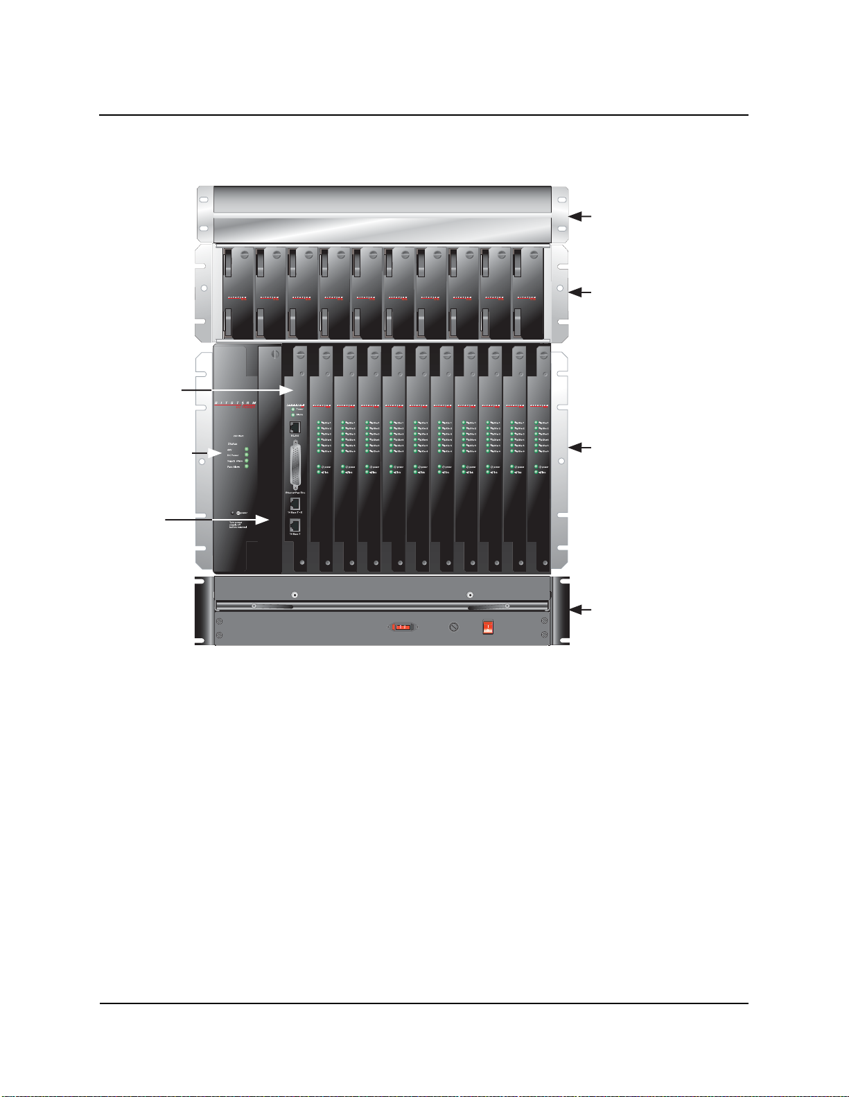
Figure 1-1,“BitStorm 1900 Shelf with Cards and Components,” on
page 2 shows the BitStorm 1900 shelf with the modem cards and basic
components installed.
1900-A2-GN20-00 BitStorm 1900 Installation and Maintenance Guide 1-1
Page 18
1. BitStorm 1900 IP DSLAM
Figure 1-1: BitStorm 1900 Shelf with Cards and Components
MIU Card
Power Card
Air Baffle
3.5" x 18" x 13"
2 RU
Filter Shelf
5.25" x 17.5" x 11.75"
3 RU
BS 1900 Shelf
12.1875" x 17.5" x 12"
7 RU
Blank
Filler Card
Fan Tray
3.5" x 18" x 13"
02-17160
BitStorm 1900 Shelf
The BitStorm 1900 Shelf supports 60 to 240 EtherLoop lines. Each
BS1900 Shelf contains 13 card slots housing the following circuit
packs:
• Ten (10) BitStorm Multiplexer Modem Cards
• Management Interface Unit (MIU)
• Power Card
• Blank Filler Card*
* The blank filler card is used to keep the air flowing properly through the
unit.
1-2 BitStorm 1900 Installation and Maintenance Guide 1900-A2-GN20-00
Page 19

1. BitStorm 1900 IP DSLAM
The BitStorm 1900 shelf and components are installed in a standard
19” rack and can be installed in 23” racks using optional 23” mounting
ears. Up to five (5) BS1900 Systems can be installed into one rack
depending on the application and the associated required components.
Refer to "Appendix B. Cabling Specifications‚" on page 115 for typical
rack configurations.
Depending on the application/configuration, the following components
are installed in the rack with the BitStorm 1900 Shelf to comprise the
system:
Air Baffle
The Air Baffle, installed above the Filter Shelf (or the BitStorm 1900
Shelf), is used to deflect the exhaust air flow out the rear of the rack.
When more than one BS1900 system is installed in a rack, the Air
Baffle prevents the heated exhaust air of one BS1900 system from
being drawn into the shelf of the BS1900 system installed above.
Fan Tray
The Fan Tray provides forced-air cooling throughout the BS1900
system. A Fan Tray is installed under each BS1900 Shelf and contains
six forced-air cooling fans to ensure sufficient cooling for the entire
system. The -48 V DC Fan Tray is ideal for the CO (Central Office) and
the 110/220 V AC Fan Tray has been uniquely designed for enterprise
applications.
Filter Shelf Option
The Filter Shelf contains low-pass filter splitters to separate out-of
voiceband signals from the voiceband traffic between the BitStorm
modems and the external voice facility equipment. Each Filter Shelf
contains up to 10 filter cards. One filter card supports 12 EtherLoop
lines installed in the BS1900 shelf. Depending on the application, more
than one Filter Shelf can be installed, one on top of another.
1900-A2-GN20-00 BitStorm 1900 Installation and Maintenance Guide 1-3
Page 20
1. BitStorm 1900 IP DSLAM
The following table provides information on some common
configurations and the number of Filter Shelves required for each
installation.
Configuration Number of Filter Shelves
Ten 10224 CO Modem Cards
(each 10224 card supports
24 lines)
Ten 10306 CO Modem Cards
(each 10306 card supports
6lines)
Each Filter Shelf can filter up to 120 lines and requires 3RU of rack space.
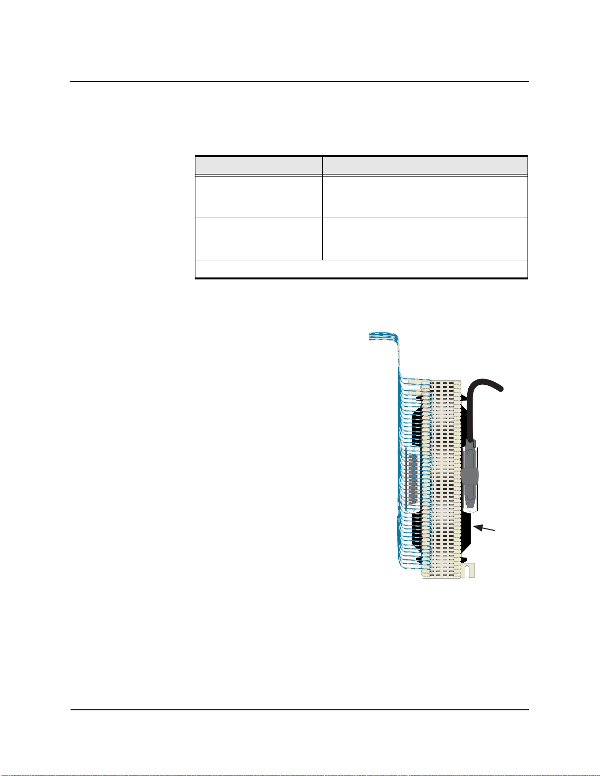
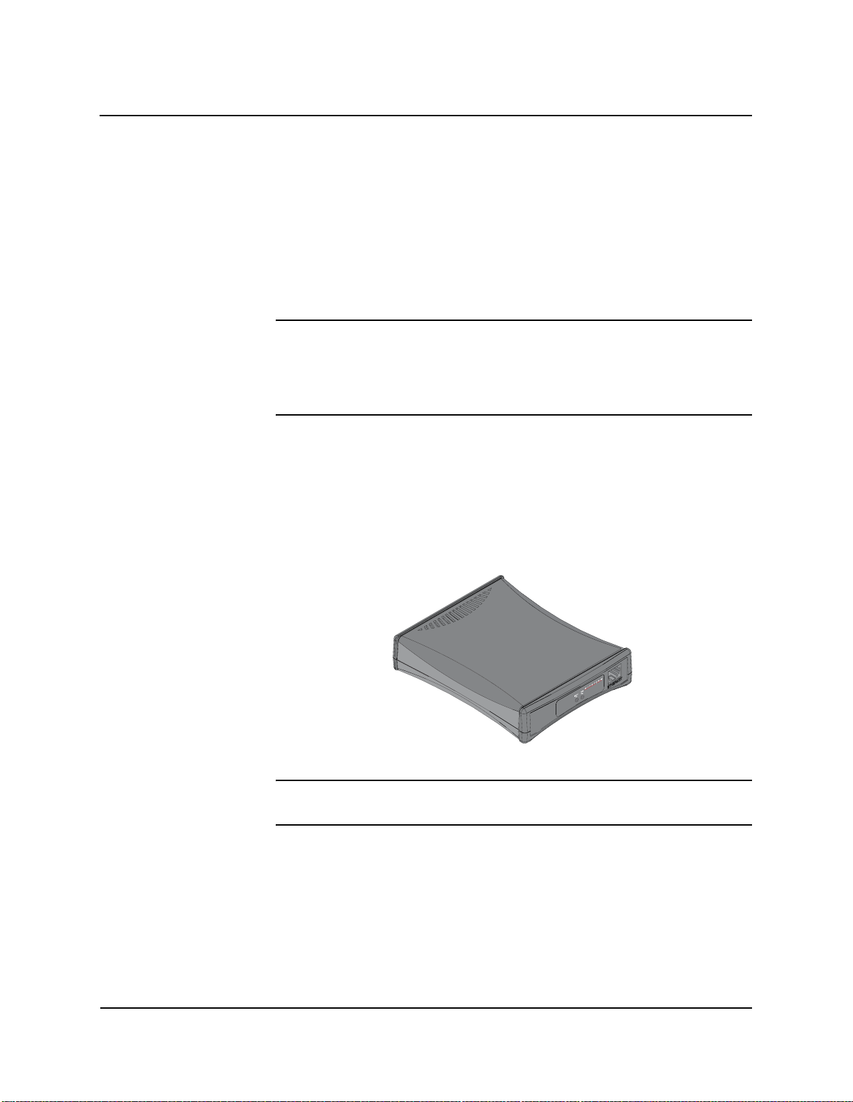
Filter 66-Block Option
The Filter 66-Block provides the
same POTS splitter function as the
Filter Shelf; however, it is a space
saving and economical alternative
to the Filter Shelf. Using the
lastest technology from Excelsus
Technologies, the Filter 66-Block
integrates a 66-Block with a PCB
(Printed Circuit Board) Filter,
eliminating the need for a Filter
Shelf, saving rack space and
reducing the number of cables
necessary for the installation. Each
Filter 66-Block can filter up to
24 lines.
2 Filter Shelves
(one 10224 card requires two filter cards)
1/2 Filter Shelf or 5 filter cards
(two 10306 cards require one filter card)
Integrated
PCB
Filter
Filter 66-Block
02-17161
1-4 BitStorm 1900 Installation and Maintenance Guide 1900-A2-GN20-00
Page 21

1. BitStorm 1900 IP DSLAM
The following table compares the number of BS1900 systems that can
be installed into a standard 7’ rack using the Filter Shelf or Filter 66Block options:
Number of BS1900
Configuration
10306 CO Modem Cards 3 4
10224 CO Modem Cards 3 4
Systems Installed in a
Rack with Optional
Filter Shelf
Number of BS1900
Systems Installed in a
Rack with Optional
Filter 66-Block
The remainder of this chapter covers features of the BitStorm System
and the CO modem card and component specifications. For further
technical information on the BitStorm 1900 System, refer to
Appendix A section "BS1900 System Specifications‚" on page 108 for
detailed information.
1900-A2-GN20-00 BitStorm 1900 Installation and Maintenance Guide 1-5
Page 22
1. BitStorm 1900 IP DSLAM
!
CO Modem Cards
One BitStorm 1900 shelf supports up to 10 modem cards. Each CO
modem card controls the StormPort CPE modems, directing data traffic
flow between the CPE modems and the data network.
WARNING: POSSIBLE EQUIPMENT DAMAGE! To
comply with Telcordia GR-1089-CORE,
Outside Plant Voltage/Current Limiting
Protection is required for each Outside Plant
Exposed line.
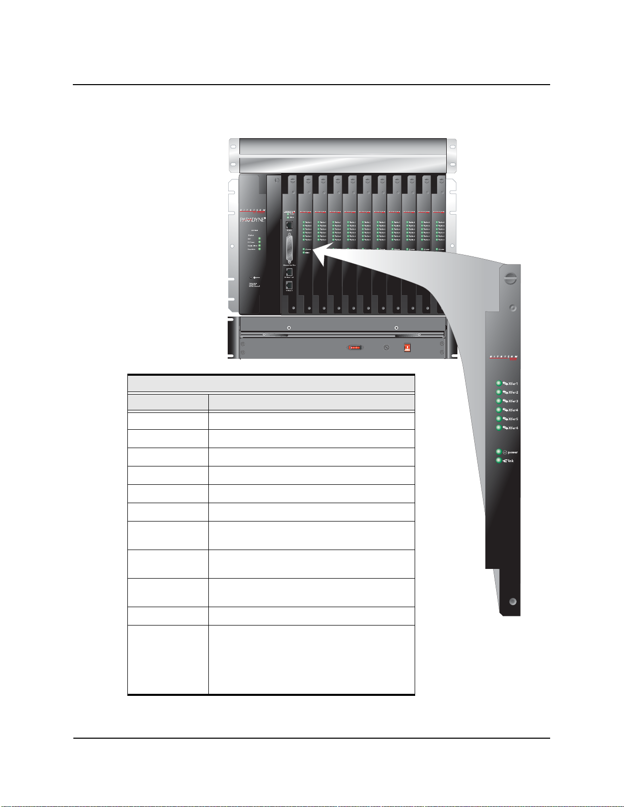
The following CO modem cards are available:
• 10306 CO modem card – 6-port dedicated, 10 Mbps
• 10224 CO modem card – 24-port statistically multiplexed,
10 Mbps
Table 1-1: CO Modem Card LEDs
LED Color
Power Green when power is on
Transfer Green when data transfer is normal (blinks when training to
find correct speed)
Link Green when network is in normal operation (amber while
training, or network is down)
Privacy Management
The Privacy Management (a.k.a. MAC Address Filtering) feature
ensures the privacy of each user connected to a local layer 2 network.
StormTracker EMS or the Site Manager is used to enter the MAC
address of a gateway or router to connect to the internet or a local
server in the StormPort CPE modem Privacy Management filter table.
The Privacy Management ensures that downstream packets are
discarded unless they are from one of the MAC addresses in the filter
table and upstream packets are discarded unless they are going to one
of the MAC addresses in the filter table. Thus, it is impossible for a
user connected to one CPE modem to see another user on the same
local L2 network connected to another CPE modem, unless the user’s
1-6 BitStorm 1900 Installation and Maintenance Guide 1900-A2-GN20-00
Page 23

1. BitStorm 1900 IP DSLAM
computer’s MAC address is entered into the Priva cy Management filter
table.
NOTE: Creating a filter table on a 10224 CO modem affects all
EtherLoop ports on that card and one of it s CPEs is redund ant,
but possible. However, the CO table should be the same or be a
superset of the CPE table.
Same Card Broadcast
The Same Card Broadcast feature is an option on CO modems that
should be used in conjunction with Privacy Management to provide
secure communications (default is Disabled):
Refer to Table 1-2, “Same Card Broadcast Feature Enabled/Disabled
Function for CO Modems,” for the feature function and security issues
associated with each setting.
Table 1-2: Same Card Broadcast Feature Enabled/Disabled Function for CO Modems
CO
Modem
10306
10224
Enabled/
Disabled
Enabled
(Default)
Disabled
Enabled
(Default)
Disabled
Feature Function Security
Allows clients on circuit s 1, 2, 3 or circuit s 4, 5, 6 to
communicate with each ot her without going out into
the network first.
Blocks clients on the same group-of-three from
seeing and comm un ica t in g w it h ea ch other, unless
the traffic exits the DSLAM and returns from the
network.
Allows clients on circuits 1–12 or circuits 13–24 to
communicate with each ot her without going out into
the network first.
Blocks clients on the same group-of-12 from seeing and communicating with eac h other, unless the
traffic exits the DSLAM and returns from the network.
N/A
Clients on other groups-ofthree or other cards c an se e
each other unless Privacy
Management is used.
N/A
Clients on other groups-of12 or other cards can see
each other unless Privacy
Management is used.
The Same Card Broadcast feature is selected from StormTracker Site
Manager and the modems are recognized as having the feature enabled
or disabled.
1900-A2-GN20-00 BitStorm 1900 Installation and Maintenance Guide 1-7
Page 24

1. BitStorm 1900 IP DSLAM
Spectrum Manager ADSL Protect
The Spectrum Manager software makes EtherLoop spectrally
compatible with asymmetrical services such as ADSL and G.Lite,
detecting and protecting against interference within the same binder . In
addition, EtherLoop in its native state is spectrally compatible with
symmetrical digital services such as T1, HDSL, HDSL2, or SDSL.
Spectrum Manager operates under five modes of operation:
Mode Description
Native EtherLoop operates without the analysis of other service activ-
ity in the individual loops.
Monitor Spectrum Manager analyzes other services in the loop that
may limit EtherLoop performance.
Forced EtherLoop provides optimum spectrally compatible perfor -
mance with asymmetric services in the individual loop that
may temporarily af fect Et herLoo p’ s ups tream c apa bility. In this
mode, EtherLoop is forced to “mimic” asymmetric DSL.
Auto-Protect EtherLoop operates in an Asymmetric Mode if asymmetric
interferers are present. EtherLoop returns to normal upstream
operations once the interference is gone.
Video Protect EtherLoop operates i n a forced Asym metric Mode w ith gu aran-
teed high downstream bandwidth for the delivery of streaming
video applications.
Spectrum Manager-Video Protect
The Spectrum Manager-Video Protect activates the EtherLoop
asymmetrical operation with all upstream traffic limited to a training
speed of 25 (3 Mbps) on the BitStorm 10306 CO modems.
Downstream traffic continues to run as fast as the loop conditions
allow . When this feature is enabled, all nearby EtherLoop lines running
high-speed video downstreams are protected. All CO modems at a site
are required to have the feature enabled by StormTracker Site Manager
or EMS via the MIU SNMP agent.
1-8 BitStorm 1900 Installation and Maintenance Guide 1900-A2-GN20-00
Page 25

Passes VLAN Tagged Frames
The BitStorm 1900 is capable of passing 802.1Q tagged Ethernet
frames of 1522 bytes. To implement a VLAN solution, a 802.1Q
tagging switch must exist upstream. Also, an 802.1Q tagging switch or
device must be present on the customer end of the CPE modem.
WAN Interface Cards
The BitStorm 1900 supports the following WAN interface:
• MIU (Management Interface Card) – supports 10306 and 10224
modem cards
MIU SNMP Functionality
The MIU provides remote monitoring and configuration functionality
via SNMP (Simple Network Management Protocol). Through the
SNMP agent, users can remotely manage and configure modem
settings and monitor the performance statistics of all modems in the
BitStorm 1900 system.
1. BitStorm 1900 IP DSLAM
The MIU SNMP agent supports the SNMPv1/RFC 1157 protocol and
supports RFC 1213 MIB II interface groups and the RFC 1493 Bridge
MIB. The MIU SNMP agent also includes an EtherLoop private MIB.
In order to manage the SNMP agent, the user must load our private
MIB into the user’s SNMP Network Manager using the procedure
accompanying the specific Network Management Software (i.e., HP
Openview, etc.).
A list of all supported MIBs and the private MIB can be found in
document 1900-A2-GK40, BitS torm 1900 IP DSLAM Supported SNMP
MIBs. This document and private MIBs can be downloaded from the
Paradyne website at www.paradyne.com.
1900-A2-GN20-00 BitStorm 1900 Installation and Maintenance Guide 1-9
Page 26
1. BitStorm 1900 IP DSLAM
Mixing CO Modem Cards
StormPort CPE Modems
It is possible to fill a BitStorm 1900 shelf with different modem cards
(i.e., five 10306 CO modem cards, and five 10224 CO modem cards).
For the 10306 CO modem cards, Spectrum Manager includes a Video
Protect mode that protects EtherLoop heavy downstream traffic from
disrupting upstream traffic on adjacent EtherLoop lines.
NOTE: The BitStorm 19 00 CO modem ca rd port s ar e provisioned in the
CO & CPE Add/Search functions of the Database module in the
StormTracker Site Manager application. The modem database
is auto-provisioned, identifying the physical shelf slot location
of each mo de m .
The BitStorm 1900 system supports the StormPort 610, 620, and 1020
CPE (customer-premises equipment) modems.
610
02-17162
NOTE: The StormPort 1020 CPE modem works at full 10 Mbps capacity
with the 10306 or 10224 CO modems.
1-10 BitStorm 1900 Installation and Maintenance Guide 1900-A2-GN20-00
Page 27

10 Mbps CO Modem Card Specifications
!
10306 CO Modem Card
The 10306 CO modem card provides six EtherLoop lines, each with its
own dedicated 10 Mbps modem.
WARNING: POSSIBLE EQUIPMENT DAMAGE! To
comply with Telcordia GR-1089-CORE,
Outside Plant Voltage/Current Limiting
Protection is required for each Outside Plant
Exposed line.
Special Features
• Same Card Broadcast
1. BitStorm 1900 IP DSLAM
• Spectrum Manager – ADSL Protect
• Spectrum Manager – Video Protect
• Privacy Management
• IP Multicast Operation
1900-A2-GN20-00 BitStorm 1900 Installation and Maintenance Guide 1-11
Page 28
1. BitStorm 1900 IP DSLAM
Figure 1-2: BitStorm 1900 with 10306 Modem Cards (Part #: 01-00153-01)
10306 CO Modem Specifications
Description Specification
Shelf Interface 100Base-T Ethernet Bus
WAN Interface MIU
Line Interface 35-pin Omni Grid connector
Heat Dissipation 22 watts
LEDs Power, Link, Data Transfer (6 lights)
Card Dimensions 12” H (7RU) x 11”D
Operation
Temperature
Short-term Operat-
ing Temperature:
Certifications FCC Part 15, Subpart B, Class A, UL 60950, cUL,
Power Supply 260 W DC or 260 W AC
Fan Tray Mandatory, use -48 V DC with 260 W DC power
5oC to 40oC (41oF to 104oF)
-5oC to 50oC (23oF to 122oF)
NEBS Level 3, CE, TNV-3, ETSI ETS 300 386-2
supply; use 110 V AC with 260 W AC power supply
• An AC fan tray air filter frame must be installed
without an air filter for AC configurations
• A DC fan tray with an air filter installed is required
for NEBs compliant DC configurations
02-17163
1-12 BitStorm 1900 Installation and Maintenance Guide 1900-A2-GN20-00
Page 29
1. BitStorm 1900 IP DSLAM
!
Table 1-3: System Power Specifications with 10306 CO Modem
Power Bit Storm 1900
Configuration
DC 260 W DC power supply 10306* 60 260 4.4 305 6.4
AC 260 W AC power supply 10306* 60 230 3.8 335 3.1
* Configuration assumes 10 modem cards are used.
Modem
Cards
WARNING: POSSIBLE EQUIPMENT DAMAGE! AC Fan
# Lines Power
(Watts)
Trays are shipped with an air filter frame. To
ensure proper airflow, the frame must
installed. DO NOT install an air filter for the
AC Fan Tray, only the frame.
Watts
Per
Line
Watts
w/Fan
Tray
Current
be
10306 CO Modem IP Multicast Operation
An optional feature of the 10306 CO modem card is the ability to pass
IP Multicast traffic only to the subscribing port. The 10306 modem
card functions as a multi-layer switch and supports IGMP v1/v2 when
connected to the MIU (Management Interface Unit) card via the 100
Base-T Ethernet backplane connection. The 10306 modem creates Port
T able data when a client joins a multicast group and forwards the IGMP
message upstream through the MIU to an IGMP-enabled Switch. When
the IP Multicast data is streamed back to the 10306, it replicates and
forwards the IP Multicast streams ONLY to the ports with subscribing
clients.
Max
1900-A2-GN20-00 BitStorm 1900 Installation and Maintenance Guide 1-13
Page 30
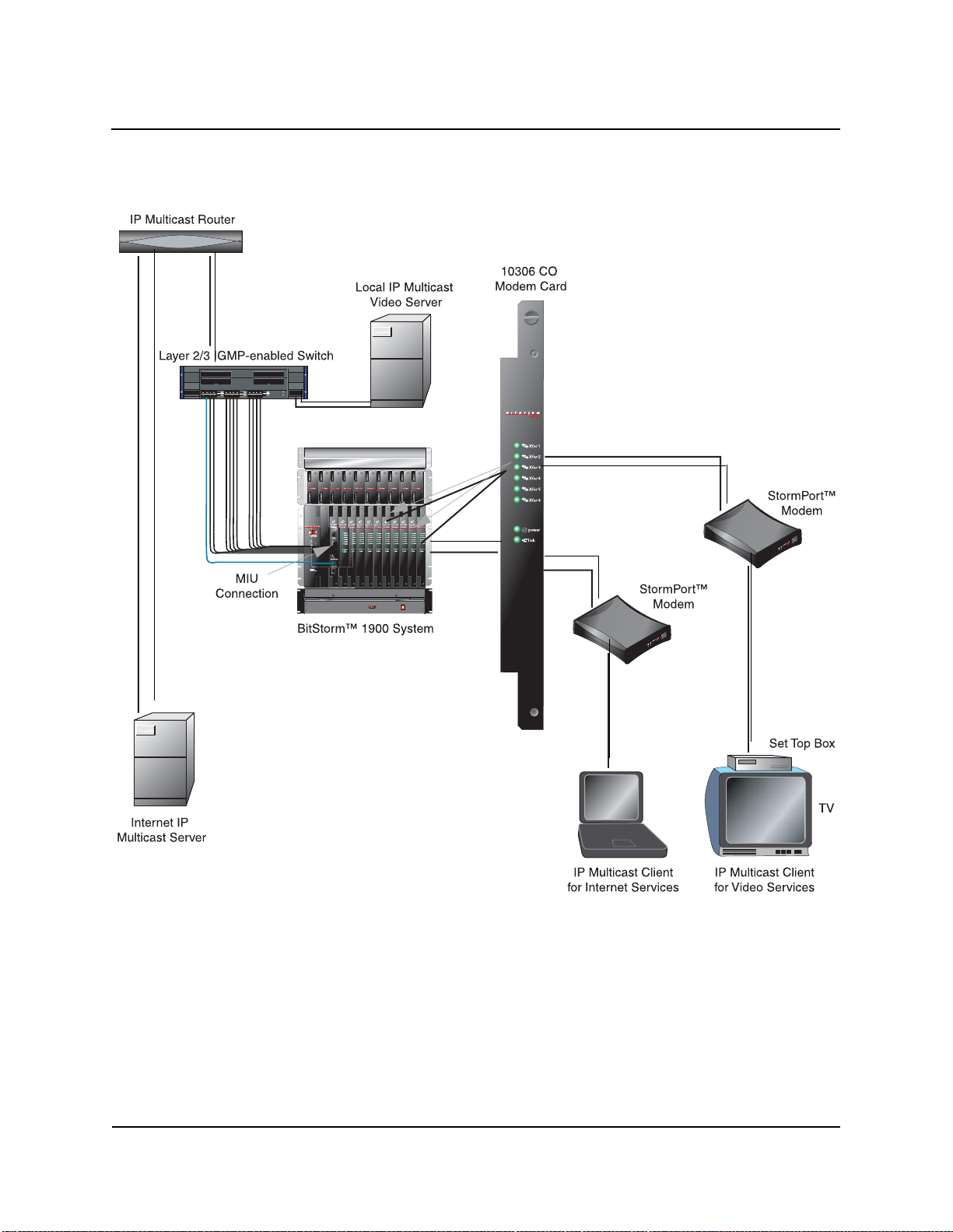
1. BitStorm 1900 IP DSLAM
Figure 1-3: 10306 IP Multicast Operation
02-17164
1-14 BitStorm 1900 Installation and Maintenance Guide 1900-A2-GN20-00
Page 31

1. BitStorm 1900 IP DSLAM
The 10306 IP Multicast Operation works in the following manner:
1. The client issues an IGMP Join Request (Unsolicited report)
Layer 2 broadcast.
2. The 10306 modem listens for any IGMP packets (IGMP snooping)
and maintains a table mapping the IP Multicast stream to the port.
3. The 10306 forwards the IGMP Join Request upstream through the
MIU to the IGMP-enabled switch.
4. The IGMP-enabled Switch “snoops” for the IGMP messages and
builds a mapping of IP Multicast streams to its Ethernet port interfaces.
5. The Switch forwards the IGMP report on behalf of the IP Multicast
client to the upstream Multicast Router.
6. The Multicast Router utilizes a multicast routing protocol (such as
MOSPF, DVMRP, etc.) to route available multicast streams.
7. Once the IP Multicast stream is received at the IGMP-enabled
Switch, it replicates and forwards the packets on all ports with
active members of that IP Multicast group.
8. The 10306 replicates and forwards IP Multicast streams ONLY to
the ports with subscribing clients.
9. When the member clients issues an IGMP Leave, the 10306
receives that message, forwards it to the upstream IGMP-enabled
Switch, and then generates a series of “quick query” packets on the
downstream port (default response time of 100 milliseconds,
repeated 3 times.) This query will allow the 10306 modem to determine if there are any remaining client members of the IP Multicast
group being left on that port, such as a second set-top box. If no
IGMP Group Membership response is received, the 10306 modem
will update the IP Multicast bridge table and no longer forward that
IP Multicast stream to that port.
10. The query response time value and number of quick queries sent
are provisionable parameters, and can be adjusted to better interoperate with a variety of client devices, such as IP television set-top
boxes. Refer to the StormT racker -Site Manager and Administration
User Guide for more information.
11. The 10306 modem relies on an upstream IGMP enabled router or
switch to send Group Membership query messages.
1900-A2-GN20-00 BitStorm 1900 Installation and Maintenance Guide 1-15
Page 32

1. BitStorm 1900 IP DSLAM
!
10224 CO Modem Card
The 10224 CO modem card provides 24 statistically multiplexed
EtherLoop lines; 12 per single 10 Mbps modem.
NOTE: The 10224 is recommended for use on loops up to 6000’ long.
WARNING: POSSIBLE EQUIPMENT DAMAGE! To
comply with Telcordia GR-1089-CORE,
Outside Plant Voltage/Current Limiting
Protection is required for each Outside Plant
Exposed line.
1-16 BitStorm 1900 Installation and Maintenance Guide 1900-A2-GN20-00
Page 33

1. BitStorm 1900 IP DSLAM
Figure 1-4: BitStorm 1900 with 10224 Modem Cards (Part #: 01-00164-01)
10224 CO Modem Specifications
Description Specification
Shelf Interface 100Base-T Ethernet Bus
WAN Interface MIU
Line Interface Dual 35-pin Omni Grid connector
Heat Dissipation 12 watts
LEDs Power, Link, Data Transfer (2 lights)
Card Dimensions 12” H (7RU) x 11”D
Operation
Temperature
Short-term Operat-
ing Temperature:
Certifications FCC Part 15 Class A, UL 60950, cUL, CE,
Power Supply 260 W DC or 260 W AC
Fan Tray Mandatory, use -48 V DC with 260 W DC power
5oC to 40oC (41oF to 104oF)
-5oC to 50oC (23oF to 122oF)
ETSI ETS 300 386-2, TNV-3
supply; use 110 V AC with 260 W AC power supply
• An AC fan tray air filter frame must be installed
without an air filter for AC configurations
• A DC fan tray with an air filter installed is required for
DC configurations
02-17165
1900-A2-GN20-00 BitStorm 1900 Installation and Maintenance Guide 1-17
Page 34

1. BitStorm 1900 IP DSLAM
Table 1-4: System Power Specifications with 10224 CO Modem
Power Bit Storm 1900
Configuration
DC 260 W DC power supply 10224* 240 160 0.7 205 4.3
AC 260 W AC power supply 10224* 240 150 0.6 255 2.3
Modem
Cards
# Lines Power
(Watts)
Watts
Per
Line
Watts
w/Fan Tray
Current
* Configuration assumes 10 modems cards are used.
Max
1-18 BitStorm 1900 Installation and Maintenance Guide 1900-A2-GN20-00
Page 35

WAN Interface Card Specifications
The BitStorm 1900 system supports the MIU (Management Interface
Unit) WAN interface.
MIU (Management Interface Unit)
The MIU is the recommended WAN interface for the BitStorm 1900.
Seated next to the modem cards, the MIU processes Ether net traf fic an d
manages modems. The MIU provides powerful management
capabilities including SNMP and the flexiblit y of mixing and matc hing
modem cards for varied configurations.
The primary functions of the MIU are Ethernet Pass-Thru and Modem
Management/Auto-Discovery/Auto-Provisioning. When initialized, the
MIU automatically discovers and auto-provisions modems, on its shelf,
by writing a Shelf ID for each modem card in the shelf via an out-ofband I²C configuration channel. Thereafter, the assigned modems will
only respond to commands from the associated MIU via the in-band
Ethernet connection.
1. BitStorm 1900 IP DSLAM
Modem parameters can also be set in the Add/Search modem links
of the Database module in Site Manager.
The MIU communicates with the Site Manager or EMS, via TCP/IP,
which extends the flexibility of remote equipment location(s) and
network management. Each MIU requires only one
MIU IP address) to manage all modems within a shelf. The MIU uses
the Modex Daemon protocol to communicate directly with EtherLoop
CO and CPE modems.
An SNMP agent has been incorporated into the MIU which allows
SNMP PC programs such as the StormTracker EMS 2.x or Castle
Rock’s SNMPc to manage the MIU and EtherLoop modems. The
SNMP MIBs, including MIB II RFC 1213 and the EtherLoop MIB, are
listed in document 1900-A2-GK40, BitStorm 1900 IP DSLAM
Supported SNMP MIBs. MIBs are available from the Paradyne website
at www.paradyne.com.
IP address (the
1900-A2-GN20-00 BitStorm 1900 Installation and Maintenance Guide 1-19
Page 36

1. BitStorm 1900 IP DSLAM
Figure 1-5: BitStorm 1900 with MIU (Part #: 01-00075-01) and 10306 CO Modems
MIU CO Modem Specifications
Description Specification
Shelf Interface 10/100Base-T Ethernet Bus
WAN Interface 50 Pin AMP Ethernet Pass-Thru, 10Base T-X
Craft Interface RS-232 RJ11 (DB9 to RJ11 connector and cable
included)
Heat Dissipation 4 watts
LEDs Power (green indicates power is on), Alarm (red indi-
Card Dimensions 12” H (7RU) x 11”D
Operation
Temperature
Short-term Operat-
ing Temperature
Certifications FCC Part 15, Subpart B, Class A, UL 60950, cUL, CE,
Power Supply 260W AC or DC
Fan Tray Mandatory, use -48 V DC with 260 W DC power sup-
cates internal problem with MIU), Link for 10Base T-X
(two lights – yellow indicates receive/transmit traffic;
green indicates link is operational)
5oC to 40oC (41oF to 104oF)
-5oC to 50oC (23oF to 122oF)
NEBs Level 3, ETSI ETS 300 386-2
ply; use 110 V AC with 260 W AC power supply
RS-232 RJ11
Craft Interface
Port
Ethernet
Pass-Thru
Management
WAN Port
10Base T-X
Crossed
Inactive Port
Uncrossed
02-17166
Cables “Decapus” Pass-Thru Cable w/10 RJ-45 (included)
1-20 BitStorm 1900 Installation and Maintenance Guide 1900-A2-GN20-00
Page 37

BitStorm ™ Server
1. BitStorm 1900 IP DSLAM
Figure 1-6: MIU Data Connection
BITST RM
SERVER
*Server can be
co-located or remote
Layer 2/3 Switch
1
2 3 4
LINK
/A
CT
100Mb/s
/A
CT
LINK
100Mb/s
6
7
8
5
Management Commands
Software
Applications
Site Manager
Spectrum Manager
Etc.
1
8
1
9
2
0
1
7
LINK
/A
CT
100Mb/s
/A
CT
LINK
100Mb/s
21
22 34 24
LINK
/A
CT
100Mb/s
LINK
/A
CT
100Mb/s
TCP/IP
POWER
RE
ADY
Hospitality /VBN
Carrier
BitStorm™ 1900
IP Address
Mode-X
Daemon
SNMP
I2C Bus
for Auto-
Provisioning
Modem Cards
610
StormPort™
Modem
02-17167
1900-A2-GN20-00 BitStorm 1900 Installation and Maintenance Guide 1-21
Page 38

1. BitStorm 1900 IP DSLAM
Power Card Specifications
The power cards convert the power feeds to the +12, +5, +3.3, -5 and
+2.5 V DC power levels used by the BitStorm 1900 components.
260 W DC
The 260 W DC power card converts the -48 V DC power feed to the
power levels used by the 10306 and 10224 CO modem cards.
Application: The 260 W DC power card is required for the 10306 and 10224 CO
modem cards and MIU.
1-22 BitStorm 1900 Installation and Maintenance Guide 1900-A2-GN20-00
Page 39

1. BitStorm 1900 IP DSLAM
Figure 1-7: 260 W DC Power Card (Part #: 01-00080-01)
260 W DC Power Card Specifications
Description Specification
Card Dimensions 12” x 2.27” x 11.75”
LEDs -48V, DC Power, Supply Alarm, Fuse Alarm
Input -48V DC (Refer to Table 1-3, “System Power Specifications with
Cord Mate-n-Lock connector, 18’ included
Fan Tray A 260 W DC fan tray is required
Operating
Temperat ure
Short-term Operat-
ing Temperature
Certifications FCC Part 15, Class A, UL 60950, cUL, NEBS level 3, CE,
-48 V DC Supply
Fuse
10306 CO Modem,” on page 13, and Table 1-4, “System Power
Specifications with 10224 CO Modem,” on page18).
5oC to 40oC (41oF to 104oF)
-5oC to 50oC (23oF to 122oF)
ETSI ETS 300 386-2
10 AMP, -48 V DC Supply Fuse
02-17168
1900-A2-GN20-00 BitStorm 1900 Installation and Maintenance Guide 1-23
Page 40

1. BitStorm 1900 IP DSLAM
260 W AC
Application: Required with 10306 and 10224 CO modem cards with AC power
The 260 W AC power card converts the 110/220 V AC power feed to
the power levels used by the 10603 and 10224 CO modem cards and
the MIU.
supply.
1-24 BitStorm 1900 Installation and Maintenance Guide 1900-A2-GN20-00
Page 41

1. BitStorm 1900 IP DSLAM
Figure 1-8: 260 W AC Power Card (Part #: 01-00079-01)
260 W AC Power Card Specifications
Description Specification
Card Dimensions 12” x 2.27” x 11.75”
LEDs 12V DC, 5 V DC, 3.3V DC,-5 V DC
Input 85 – 265 V AC, 47 – 63 Hz
Cord IEC 320, (6’)
Operating
Temperature
Short-term Operat-
ing Temperature
Certifications FCC Part 15, Class A, UL 60950, cUL,
AC Supply Fuse 3 AMP – 250 V AC
Fan Tray An AC fan tray is required
5oC to 40oC (41oF to 104oF)
-5oC to 50oC (23oF to 122oF)
NEBS level 3, CE, ETSI ETS 300 386-2
ON/OFF
FUSE
(3A, 250V AC)
02-17169
1900-A2-GN20-00 BitStorm 1900 Installation and Maintenance Guide 1-25
Page 42

1. BitStorm 1900 IP DSLAM
Fan Tray Specifications
The -48V DC fan tray and the 110/220V AC (switch selectable) fan
tray are used with the BitStorm 1900 in EtherLoop applications to
provide forced-air cooling in each chassis. A fan tray is required under
each chassis that houses one or more 10306 or 10224 CO modem cards.
Fan Tray 110/220 V AC
Figure 1-9: Fan Tray 110/220 V AC (Part #: 01-00084-02)
115/230V AC
(Switch Selectable)
FUSE
(2 AMP, 250V AC) ON/OFF
02-17170
Fan Tray 110/220 V AC Specifications
Operating Temperature
Storage Temperature
Certifications UL 60950, cUL, CE
Power Consumption 105 W
Dimensions 3.5” x 18” x 13”
Filter (See Warning below) For proper air flow, install the air filter
Cord IEC 320, 6’
AC Supply Fuse 2 AMP, 250 V AC
0oC to 40oC (0oF to 104oF)
o
-40
C to 70oC (-40oF to 158oF)
frame only. DO NOT install an air filter
with the frame.
1-26 BitStorm 1900 Installation and Maintenance Guide 1900-A2-GN20-00
Page 43

!
WARNING: POSSIBLE EQUIPMENT DAMAGE! AC Fan
Trays are shipped with an air filter frame. To
ensure proper airflow, the frame must
installed. DO NOT install an air filter for the
AC Fan Tray, only the frame.
Table 1-5: Power Specifications for the AC Fan Tray
1. BitStorm 1900 IP DSLAM
be
Power Bit Storm 1900
Configuration
AC AC Fan Tray n/a n/a 105 n/a n/a .9
Modem
Cards
# Lines Power
(Watts)
Watts
per line
Watts
w/fan tray
Max
current
1900-A2-GN20-00 BitStorm 1900 Installation and Maintenance Guide 1-27
Page 44

1. BitStorm 1900 IP DSLAM
Fan Tray -48 V DC
Figure 1-10: Fan Tray -48 V DC (Part #: 01-00084-01)
Audible Alarm Fan Failure LEDs ON/OFF
Fan Tray -48 V DC Specifications
Operating Temperature
Storage Temperature
Certifications UL 60950, cUL, NEBS Level 3 CE
Power Consumption 45W
Dimensions 3.5” x 18” x 13”
NEBS Air Filter Change every 6 months
Cord 14-gauge stranded cable (not included)
-48 V DC Supply Fuse 2 AMP, -48 V DC Supply Fuse
o
0
C to 40oC (0oF to 104oF)
o
-40
C to 70oC (-40oF to 158oF)
Table 1-6: Power Specifications for the DC Fan Tray
02-17171
Power Bit Storm 1900
Configuration
DC DC Fan Tray n/a n/a 45 n/a n/a .9
1-28 BitStorm 1900 Installation and Maintenance Guide 1900-A2-GN20-00
Modem
Cards
# Lines Power
(Watts)
Watts
per line
Watts
w/fan tray
Max
current
Page 45

Low-Pass Filter Specifications
Filter Shelf
Low-Pass filters are used with the BitStorm 1900 in EtherLoop
applications where voice service is required. The low-pass filter cards
separate out-of-voiceband signals from the voiceband traffic between
the BitStorm modems and the external voice facility equipment. The
Low-Pass Filter Shelf contains one filter card for every two 10306
modem cards, or two filter cards for every 10224 modem card.
The filter shelf connects to the distribution frame, designed to minimize
signal interference and facilitate broadband connectivity by isolating
Digital Service Units (DSUs) from the Private Branch Exchange
(PBX). Refer to Figure 1-11 on page 30 for Filter Shelf Specifications.
Filter 66-Block
1. BitStorm 1900 IP DSLAM
The Filter 66-Block provides the same function as the filter shelf,
however, it is a space saving and economical alternative to the filter
shelf for large enterprise installations. Refer to Figure 1-11 on page 30
for Filter 66-Block Specifications.
1900-A2-GN20-00 BitStorm 1900 Installation and Maintenance Guide 1-29
Page 46

1. BitStorm 1900 IP DSLAM
Figure 1-11: Filter Shelf (Filter Shelf Part #: 01-20029-01, Filter Card Part #: 01-20029-01, and Filter
66-Block Part #: 05-00021-01)
Front Panel
*Back Panel
02-17172
Filter
66-Block
Filter Shelf Specifications
Shelf Dimensions 5.25” x 17.5” x 11.75”
Card Dimensions 4.75” x 1.5” x 11.25”
Third-Order
Low-Pass Filters
Certifications UL 60950, cUL, NEBs Level 3, CE,
Connectors 10 Omni-Grid Connectors
Cables Re fer to Appendix B: Cabling Specifi-
insertions loss < .5 dB to 12 kHz 60
kHz stop-band loss>30 dB 100 Ohm
return loss> 20 dB to 12 kHz
ETSI ETS 300 386-2
cations.
Filter 66-Block Specifications*
Dimensions 10” x 4.5” x 2.75”
Connectors Amp Champ
* For more detailed specifications on the Filter 66-Block,
refer to the Excelsus T echno logies Spec Sheet located on
their website at excesus-tech.com.
1-30 BitStorm 1900 Installation and Maintenance Guide 1900-A2-GN20-00
Page 47

BitStorm 1900 Component Requirements
!
!
Table 1-7, “BitStorm 1900 Component Requirements,” provides the
basic requirements for each component within the shelf.
Table 1-7: BitStorm 1900 Component Requirements
1. BitStorm 1900 IP DSLAM
Part
Number
01-00080-01 260 W DC
01-00079-01 260 W AC
01-00075-01 MIU Yes Yes
01-00084-01 Fan Tray, DC Yes Yes
01-00084-02 Fan Tray, AC Yes Yes
WARNING: POSSIBLE EQUIPMENT DAMAGE! To
Shelf
Components
power
power
comply with Telcordia GR-1089-CORE,
Outside Plant Voltage/Current Limiting
Protection is required for each Outside Plant
Exposed line.
10306
CO
Modem
Card
Yes Yes Must use fan tray*
Yes Yes Must use fan tray
10224
CO
Modem
Card
Special
Instructions
*Air filte r is
required for NEBs
compliance
without
an air
filter
WARNING: POSSIBLE EQUIPMENT DAMAGE! AC Fan
Trays are shipped with an air filter frame. To
ensure proper airflow, the frame must
installed. DO NOT install an air filter for the
AC Fan Tray, only the frame.
1900-A2-GN20-00 BitStorm 1900 Installation and Maintenance Guide 1-31
be
Page 48

1. BitStorm 1900 IP DSLAM
1-32 BitStorm 1900 Installation and Maintenance Guide 1900-A2-GN20-00
Page 49

2. BitStorm 1900 Installation and Testing
!
The BitStorm 1900 provides EtherLoop CO modems, which
communicate with the remote StormPort CPE modems installed at the
customer premises. Installing the BitStorm 1900 consists of the
following:
• Installing the BitStorm shelf and accessories into an equipment
rack
• Connecting the BitStorm 1900 to the telephone line
• Installing the StormPort CPE modems
• Connecting the Ethernet data network
NOTE: In voice/data applications, the BitStorm 1900 shelf installation includes
an auxiliary voiceband Filter Shelf or Filter 66-Block.
This chapter contains the procedures for installing and testing the midmount and flush-mount components of the BitStorm 1900.
WARNING: POSSIBLE EQUIPMENT DAMAGE! To
comply with Telcordia GR-1089-CORE,
Outside Plant Voltage/Current Limiting
Protection is required for each Outside Plant
Exposed line.
1900-A2-GN20-00 BitStorm 1900 Installation and Maintenance Guide 2-33
Page 50

2. BitStorm 1900 Installation and Testing
Installation Flowchart
Figure 2-1, "BitStorm 1900 Installation Flowchart." provides a visual
flowchart of the BitStorm 1900 installation process as a reference tool.
Figure 2-1: BitStorm 1900 Installation Flowchart
Start
AC
Verify AC Power is
Available
Verify
Rack
Space,
Power and
Grounding
using a Filter
using a Filter
Are you
Shelf
Yes
No
Are you
Shelf
Install
Rack and
Connect to
Building
Ground
?
on top of BitStorm
?
Install
Power
No
Install
Filter Shelf(s)
1900 Chassis
Install
Interconnecting
cables to the
BitStorm 1900
Strip
Install Air Baffle
On Top
Are you
Installing an
AC or DC Power
Card
?
DC
Install appropriate
cards into the
BitStorm 1900
Install -48VDC
Power Source
Install
Interconnecting
cable to the MD
Install
MIU
Card
Verify Power and
Connect to
BitStorm 1900
Turn Power
F
On
Install Fan Tray
(leave 1RU of space
below for proper air flow).
Verify Power Card is
260W.
Install BitStorm 1900
Chassis directly on top
of Fan Tray or 1 RU
from bottom of rack
Install appropriate
Ethernet data
connects to
the MIU
Configure the MIU
and Remote
Management
SNMP
Test System
End
02-17173
Yes
Install Interconnecting
cables to the Filter
Shelf. Refer to
Appendix B for various
configurations
Install Interconnecting
cable between the Filter
Shelf and BitStorm 1900.
Refer to Appendix B for
configurations
various
2-34 BitStorm 1900 Installation and Maintenance Guide 1900-A2-GN20-00
Page 51

Installation Task List
The following is a complete list of all tasks to perform. To install the
BitStorm 1900 complete each task in the order given.
Task 001: Pre-Installation Checklist 36
Task 002: Installing the 19” Fan Tray 38
Task 003: Installing the BS1900 and Filter Shelves 42
Task 004: Installing the Air Baffle 47
Task 005: Installing the Circuit Packs 48
Task 006: Connecting Power to the Shelf 49
Task 007: Installing the Data Network Connection with an MIU 54
Task 008: Installing Voice/Data & Filter Shelf Connections 58
2. BitStorm 1900 Installation and Testing
Task # and Description Page
Task 009: Installing Voice/Data w/Filter 66-Block Connections 64
Task 010: Installing the Data-only Connections 67
Task 011: Installing External Voice Switch Connections 70
Task 012: Configuring the MIU 72
Task 013: Configuring Remote Management 87
Task 014: Testing the BitStorm 1900 Installation 96
Task 015: Testing Voice Connectivity 99
Task 016: Testing Data Connectivity 100
Task 017: EtherLoop End-to-End Testing 101
Installing the BitStorm 1900
The following tasks and procedures have been provided to properly
install the BitStorm 1900 components. The installation is organized
into numbered tasks with each task containing all of the procedural
steps for completion. Complete each task in the order given and
complete each step for a task procedure in the order given before
continuing on to the next task.
1900-A2-GN20-00 BitStorm 1900 Installation and Maintenance Guide 2-35
Page 52

2. BitStorm 1900 Installation and Testing
Task 001: Pre-Installation Checklist
Before installing the BitStorm 1900 system, verify that the following
steps have been completed:
Step Procedure
1.) Perform site survey and verify equipment bays are installed
correctly.
2.) Verify that the amount of rack space is adequate for the required
installed application.
3.) Verify the racks are secured and electrically grounded according to
standard industry practice. Refer to "Appendix A. Installation
Requirements," on page 107 for specifications.
4.) Verify you have all necessary tools, equipment, and materials for
the installation. Use the following table as a guide
Table 2-8: Installation Tools, Equipment, and Materials
Tools, Equipment, and Materials
Installation hardware kit supplied with shelf
Phillips-head screwdriver (#1 or #2)
Anti-static protection such as a grounded wrist strap
Volt-oh m meter
PC with serial port to configure MIU
Cross-connect punch-down tool
14-gauge stranded cable
Cable ties
5 BitStorm 1900 cable harnesses
5 intermediate cables
Cross-connect block(s) of the same type used in the existing main distribution
frame (MDF)
24 AWG Jumper Wires (24 wires per modem card)
2-36 BitStorm 1900 Installation and Maintenance Guide 1900-A2-GN20-00
Page 53

2. BitStorm 1900 Installation and Testing
STOP
Step Procedure (continued)
5.) Verify all necessary BS 1900 system components, hardware,
circuit packs, and cables are at the installation site and that they
are in good condition. If a Materials List is provided, verify the
packing lis t w ith it.
6.) Determine if an AC or DC power card is to be used in the
configuration.
a.) If installing a DC power card, install the -48 V DC power
source.
7.) Complete all remaining tasks in the order given unless otherwise
directed.
<RXKDYHFRPSOHWHGWKLVWDVN
1900-A2-GN20-00 BitStorm 1900 Installation and Maintenance Guide 2-37
Page 54

2. BitStorm 1900 Installation and Testing
!
Task 002: Installing the 19” Fan Tray
The 19" fan tray is necessary for a chassis housing one or more 10306
or 10224 CO modem cards. The fan tray is installed under each
BS1900 shelf and contains six forced-air cooling fans to ensure
sufficient cooling for operation. Use this procedure only to connect fan
trays for use with the 10306 or 10224 CO modem cards. The following
instructions are for installation of the -48 V DC and 110/220 V AC
(switch selectable) fan trays.
Step Procedure
1.) Seat the fan tray at the bottom of the rack, leave room for at least
1 RU (Rack Unit) of air entry, then mount the two (2) side brackets
(19” mounting ears) to secure the tray in the shelf. (For 23” racks,
use 23” adapter ears.) Brackets are adjustable for flush and midmounting. Refer to Figure 2-2, "Fan Tray Mounting," on page 39.
WARNING: POSSIBLE EQUIPMENT DAMAGE! AC Fan
Trays are shipped with an air filter frame. To
ensure proper airflow, the frame must
installed. DO NOT install an air filter for the
AC Fan Tray, only the frame.
2-38 BitStorm 1900 Installation and Maintenance Guide 1900-A2-GN20-00
be
Page 55

2. BitStorm 1900 Installation and Testing
Step Procedure (continued)
Figure 2-2: Fan Tray Mounting
Flush-Mount
Mid-Mount
02-17174
2.) Connect power for -48 V DC. (If you are installing an AC fan tray,
proceed to step 3 to connect power for the 110 V AC fan tray.)
a.) The -48 V DC connection requires a 14-gauge stranded cable
(not included).
b.) Connect the black power feed to the positive terminal and the
red power feed to the negative terminal.
NOTE: This is the opposite of how non-telecommunications electronics are
connected.
c.) Route the other end to the matching connector on the BitStorm
1900 backplane.
d.) LEDs indicate fan failure.
NOTE: The power supply for the multiplexer must also be -48 V DC.
1900-A2-GN20-00 BitStorm 1900 Installation and Maintenance Guide 2-39
Page 56

2. BitStorm 1900 Installation and Testing
!
Step Procedure (continued)
3.) Connect power for the 110/220 V AC fan tray.
Figure 2-3: -48 V DC Fan Tray
a.) Connect the power cord to the IEC terminal connection on the
front panel.
b.) Route the other end to a grounded outlet.
NOTE: The power supply for the multiplexer must also be 110/220 V AC.
Figure 2-4: 110 V AC Fan Tray
WARNING: POSSIBLE EQUIPMENT DAMAGE! Be sure
to set the switch on the back panel of the
110/220 V AC fan tray to 115 V for a 1 10 V AC
connection, and 230 V for a 220 V AC
connection. Failure to do so will blow the
fuse on the front panel.
2-40 BitStorm 1900 Installation and Maintenance Guide 1900-A2-GN20-00
Page 57

2. BitStorm 1900 Installation and Testing
STOP
!
Step Procedure (continued)
4.) Install the air filter frame.
a.) The filter must be removed.
b.) Slide the frame into place.
5.) Install the air filter for the DC fan tray. (DO NOT install a filter in the
AC fan tray).
NOTE: An air filter must be installed and maintained in the DC Fan Tray for
NEBs compliance.
WARNING: POSSIBLE EQUIPMENT DAMAGE! AC Fan
Trays are shipped with an air filter frame. To
ensure proper airflow, the frame must
installed. DO NOT install an air filter for the
AC Fan Tray, only the frame.
be
a.) Verify filter is installed in the frame.
b.) Slide the unit into the fan tray.
NOTE: Installed air filters must be changed every 6 months. Bulk packs of
5 NEBs Air Filters (Part # 0100085-01) are available.
<RXKDYHFRPSOHWHGWKLVWDVN
1900-A2-GN20-00 BitStorm 1900 Installation and Maintenance Guide 2-41
Page 58

2. BitStorm 1900 Installation and Testing
!
Task 003: Installing the BS1900 and Filter Shelves
Use this procedure to install the BitStorm 1900 modem shelf and filter
shelf.
NOTE: The filter shelf is not required in data-only applications.
Requirements
This procedure requires the following:
• Equipment bay with enough space available installed, secured, and
electrically grounded according to standard industry practice
(specifications for a suitable bay are described in the Appendix A
section "Bay Requirements and Specifications," on page 107).
• Installation hardware kit supplied with shelf
• Phillips-head screwdriver (#1 or #2)
WARNING: POSSIBLE EQUIPMENT DAMAGE! DO NOT
rest objects such as tools or anyhting else
on top of the BitStorm 1900 shelves. The
mounting fasteners can only support the
weight of the shelf. Additional weight may
weaken the fasteners.
2-42 BitStorm 1900 Installation and Maintenance Guide 1900-A2-GN20-00
Page 59

2. BitStorm 1900 Installation and Testing
!
Step Procedure
1.) Select and apply grounded anti-static protection.
WARNING: ELECTROSTATIC DISCHARGE! Anti-static
protection required! The BitStorm 1900
shelves are shipped with the circuit packs
installed. When handling any circuit pack,
you must wear grounded anti-static
protection. The discharge of static electricity
can damage the circuit packs.
2.) Select the mounting point in the bay where the top holes of the
shelf mounting flanges will be attached.
WARNING: POSSIBLE EQUIPMENT DAMAGE! Installa-
tion Requirement! For a single-shelf
application without a Fan Tray, be sure to
leave at least three inches of space above
and below the BitStorm 1900 shelves to
dissipate heat.
3.) Align the holes of the shelf mounting flanges with the mounting
holes in the bay as shown in Figure 2-5, "BitStorm 1900 Modem
Shelves Mounted in Bay."
1900-A2-GN20-00 BitStorm 1900 Installation and Maintenance Guide 2-43
Page 60

2. BitStorm 1900 Installation and Testing
Figure 2-5: BitStorm 1900 Modem Shelves Mounted in Bay
Mid-Mount Flush-Mount
02-17177
4.) Using the shelf mounting screws provided in the shelf hardware kit,
fasten the left and right flanges to the bay as shown in Figure 2-6,
"BitStorm 1900 Shelf Fastened to Bay," on page 45.
2-44 BitStorm 1900 Installation and Maintenance Guide 1900-A2-GN20-00
Page 61

2. BitStorm 1900 Installation and Testing
Step Procedure (continued)
Figure 2-6: BitStorm 1900 Shelf Fastened to Bay
Shelf Mounting Screw (4)
Shelf Ground Stud
Side Flange
Bay
02-17178
5.) Proceed according to the following table:
If the application is Then
Voice/data Align a nd mount a filter shelf directly above the Bit-
Storm 1900 shelf as shown in Figure 2-7, "Filter
Shelf Mounting in Bay," on page 46.
Data-only Do not install the filter shelf.
NOTE: For a Data-only application: Stop here. You have
completed the task.
1900-A2-GN20-00 BitStorm 1900 Installation and Maintenance Guide 2-45
Page 62

2. BitStorm 1900 Installation and Testing
STOP
Step Procedure (continued)
Figure 2-7: Filter Shelf Mounting in Bay
Filter Shelf
5.25" x 17.5" x 11.75"
BS1900 Shelf
12.1875" x 17.5" x 12"
Mid-Mount
Flush-Mount
02-17179
<RXKDYHFRPSOHWHGWKLVWDVN
2-46 BitStorm 1900 Installation and Maintenance Guide 1900-A2-GN20-00
Page 63

Task 004: Installing the Air Baffle
STOP
Use this procedure to install the BitStorm 1900 Air Baffle.
Requirements
This procedure requires the following:
• Phillips-head screwdriver (#1 or #2)
Step Procedure
1.) Verify that the mounting adapters are in the same position as the
BS 1900 and the Filter Shelf (i.e., mid-mount or flush-mount).
2.) Place directly above the BS 1900 or Filter Shelf.
2. BitStorm 1900 Installation and Testing
3.) Secure with mounting screws.
<RXKDYHFRPSOHWHGWKLVWDVN
1900-A2-GN20-00 BitStorm 1900 Installation and Maintenance Guide 2-47
Page 64

2. BitStorm 1900 Installation and Testing
STOP
Task 005: Installing the Circuit Packs
Use this procedure to install the BitStorm 1900 circuit packs.
Requirements
This procedure requires the following:
• Grounded anti-static protection
WARNING: ESD (ELECTROSTATIC DISCHARGE) ! Anti-
static protection required! When handling
any circuit pack, you must wear grounded
anti-static protection. The discharge of st atic
electricity can damage the circuit packs.
Step Procedure
1.) Place anti-static strip on wrist and attach to the grounded rack.
2.) Remove the circuit pack from the anti-static packaging.
3.) Align the card in the appropriate slot.
4.) Seat the card by pressing firmly into place.
<RXKDYHFRPSOHWHGWKLVWDVN
2-48 BitStorm 1900 Installation and Maintenance Guide 1900-A2-GN20-00
Page 65

2. BitStorm 1900 Installation and Testing
!
Task 006: Connecting Power to the Shelf
Use this procedure to install the power feeds from a -48 V DC or 1 10 V
AC power source to the BitStorm 1900 modem shelf.
NOTE: The filter shelf does not require a power feed.
Requirements
This procedure requires the following:
• Volt-ohm meter
• BitStorm 1900 DC power harness
• -48 V DC power fuse bay or AC-to-DC rectifier or 110 V AC
power
Power supply and wiring specifications are described in "Appendix A.
Installation Requirements," on page 107.
Step Procedure
1.) Eject all cards (Power, MIU Shelf Processor and Modems) from the
backplane of the shelf. Ensure that the cards completely dislodge
from their backplane connecto rs.
WARNING: POSSIBLE EQUIPMENT DAMAGE! Never
connect untested power to the BitStorm
1900 with any circuit packs installed. The
BitStorm 1900 shelf and rectifier could be
seriously damaged if the power feed
polarities on a -48 V DC power supply are
reversed.
2.) Route and connect a ground wire from the building’s grounding
facility to the ground stud on the side flange of the shelf. Refer to
the Appendix A section "Grounding Environment Specifications,"
on page 109 for the BitStorm 1900 grounding requirements.
1900-A2-GN20-00 BitStorm 1900 Installation and Maintenance Guide 2-49
Page 66

2. BitStorm 1900 Installation and Testing
!
Step Procedure (continued)
3.) With the power supply turned OFF, connect the -48 V DC (260W)
or 110 VAC (260W) power source according to the following table
and Figure 2-8, "Typical DC Power Harness Connection to -48 V
DC (260W) Power Source," on page 51.
WARNING: POSSIBLE EQUIPMENT DAMAGE! With the
-48 V DC power supply, reversed polarities
on the power feed can irreparably damage
the BitStorm 1900 shelf components. Be
certain that power feeds are connected
properly to the power source, with the red
lead connected to the -48 V DC supply
(negative terminal) as shown in the table
below. Note that this is the opposite of othe r
(non-telecommunications) applications, in
which the red lead is usually connected to
the positive (+) te rminal.
Power
Lead
Red -48 V DC supply Negative (-) 10 AMP, 260W
Black -48 V DC return Positive (+)
N/A 110 V AC supply IEC 6 AMP, 26 0W
Power Source Terminal Connection Line Fuse
2-50 BitStorm 1900 Installation and Maintenance Guide 1900-A2-GN20-00
Page 67

2. BitStorm 1900 Installation and Testing
Step Procedure (continued)
Figure 2-8: Typical DC Power Harness Connection to -48 V DC (260W) Power Source
Single Power Source Rundant Power Source
Power Supply #1 Power Supply #2
BLACK LEAD
V dc Return
Positive ( + )
Terminal
RED LEAD
-48V dc
Negative ( - )
Terminal
BLACK LEAD
V dc Return
Positive ( + )
Terminal
RED LEAD
-48V dc
Negative ( - )
Terminal
02-17180
4.) For a -48 V DC power source, connect the red power lead to the
Negative (-) terminal connection and the black power lead to the
Positive (+) terminal connection as seen in Figure 2-8, "Ty pica l DC
Power Harness Connection to -48 V DC (260W) Power Source,"
on page 51.
NOTE: If using a -48 V DC power supply, use an appropriate volt-ohm meter to
test and verify that the red power feed at the shelf is the -48 V DC
supply. The meter should read between -46 and -56 V DC.
1900-A2-GN20-00 BitStorm 1900 Installation and Maintenance Guide 2-51
Page 68

2. BitStorm 1900 Installation and Testing
Step Procedure (continued)
NOTE: The redundant power supply sources connect to two pairs of wires on
5.) Route the other end of the DC power harness to the DC power
6.) For an AC power supply, connect the power cord to the IEC
Figure 2-9: Typical Power Connection to 260W AC Power Source
the BitStorm 1900’s power harness and are electrically the same.
connector on the backplane of the BitStorm 1900 modem shelf.
The connector only fits one way.
terminal connection on the front panel.
ON/OFF
FUSE
3A, 250V AC
02-17181
7.) Route the other end of the cord to a grounded socket.
8.) Re-seat the power, modem, and MIU Shelf processor into their
shelf backplane connectors.
2-52 BitStorm 1900 Installation and Maintenance Guide 1900-A2-GN20-00
Page 69

2. BitStorm 1900 Installation and Testing
STOP
Step Procedure (continued)
9.) Secure the power harness in accordance with local office
procedures.
10.) Turn ON the power to the shelf from the power supply.
<RXKDYHFRPSOHWHGWKLVWDVN
1900-A2-GN20-00 BitStorm 1900 Installation and Maintenance Guide 2-53
Page 70

2. BitStorm 1900 Installation and Testing
Task 007: Installing the Data Network Connection with
an MIU
Use this procedure to connect the BitStorm 1900 to the Ethernet data
network using an MIU.
Requirements
This procedure requires the following:
• Ethernet data network installed
• Serial cable and DB9S to RJ-11 serial adapter (included)
• PC with serial port to configure system
• Two Category 5 crossover or straight cables terminated with RJ-45
connectors according to Table 2-1.
Table 2-1: Data Cable Selection for MIU Shelf Processor
MIU Cable Requirements Application
RS-232 RJ-11 cable (a DB9S to
RJ-11 serial adapter is
included)
Ethernet Pass Thru 50-pin connector decapus
cable (DB50F) part #
04-00017-01, with 10
RJ-45 cables (included)
10 Base-T X (top port)
(Management ports
must be connected)
10 Base-T (bottom port) Not used in this release Not used in this release
RJ-45 straight cable, 6’
(included)
To a PC (for configuration only)
To Ethernet switch
To a port on an intermediate switch or hub
NOTE: Switch or hub must
have connection to
EtherLoop network
router.
Step Procedure
1.) Connect one end of the RJ-45 (crossed) cable to the switch/router,
then route the other end to the 10 Base T-X port of MIU.
2-54 BitStorm 1900 Installation and Maintenance Guide 1900-A2-GN20-00
Page 71

Step Procedure (continued)
Figure 2-10: BitStorm 1900 Data Connection via MIU
BitStorm ™ Server
Layer 2/3 Switch
2 3 4
1
LINK
CT
/A
100Mb/s
CT
/A
LINK
100Mb/s
8
7
6
5
2. BitStorm 1900 Installation and Testing
Figure 2-10 shows a typical EtherLoop data network connection
with the BitStorm 1900 using an MIU.
BITST RM
0
2
19
18
7
1
CT
/A
LINK
100Mb/s
LINK
CT
/A
100Mb/s
22 34 24
1
2
SERVER
CT
/A
LINK
POWER
100Mb/s
LINK
CT
/A
ADY
RE
100Mb/s
Hospitality /VBN
Carrier
BitStorm™ 1900
02-17182
1900-A2-GN20-00 BitStorm 1900 Installation and Maintenance Guide 2-55
Page 72

2. BitStorm 1900 Installation and Testing
Step Procedure (continued)
2.) Connect the 50-pin connector to the Ethernet Pass-Thru port, then
3.) Connect the RJ-11 cable with the adapter (DB9S to RJ-11) to the
4.) Verify that the green LED at the EtherLoop hub/router port
connect the cables at the other end to the corresponding
switch(es). Refer to Figure 2-11 (shown below).
local craft terminal (PC/laptop). Then connect the other end to the
RS-232 port on the MIU. Refer to Figure 2-11 (shown below).
illuminates, indicating connectivity is established from the
BitStorm 1900 Access Multiplexer shelf to the switch/router.
Figure 2-11: MIU Card with Cable Connections
RJ11 Serial Port
(This port connects to
the craft terminal)
Ethernet Pass-Thru
10Base T-X
(This port connects to
the switch/router)
10Base T
(This port is not
currently used)
02-17183
2-56 BitStorm 1900 Installation and Maintenance Guide 1900-A2-GN20-00
Page 73

2. BitStorm 1900 Installation and Testing
STOP
Step Procedure (continued)
5.) Proceed according to the following table:
If the application is Then
GO TO:
"Task 008: Installing Voice/Data & Filter Shelf
Connections, on page 58."
Voice/data
OR
"Task 009: Installing Voice/Data w/Filter 66Block Connections, on page 64."
GO TO:
Data-only
"T ask 0 10: Insta lling the D ata-only Connections,
on page 67."
<RXKDYHFRPSOHWHGWKLVWDVN
1900-A2-GN20-00 BitStorm 1900 Installation and Maintenance Guide 2-57
Page 74

2. BitStorm 1900 Installation and Testing
Task 008: Installing Voice/Data & Filter Shelf
Connections
Use this procedure to connect the BitStorm 1900 to the EtherLoop
cross-connect in voice/data applications.
Requirements
This procedure requires the following tools and materials:
• 10 BitStorm 1900 cable harnesses
• 10 intermediate cables
• 10 BitStorm 1900 data cables
"Appendix B. Cabling Specifications," on page 115 contains the
specifications for the cables and wiring required in this procedure.
Step Procedure
1.) Place and secure the dedicated EtherLoop cross-connect on the
facility main distribution frame.
2.) Designate and label one side of each block as "Line/CPE," and the
other side as "Voice."
3.) Review pin and pair assignments in Figu re 2-2, "Pin and Pa ir
Assignments for the Champ to Omni Grid Cable (Part #: 04-00007-
10)," on page 59.
2-58 BitStorm 1900 Installation and Maintenance Guide 1900-A2-GN20-00
Page 75

2. BitStorm 1900 Installation and Testing
Step Procedure (continued)
Table 2-2: Pin and Pair Assignments for the Champ to Omni Grid Cable (Part #: 04-00007-10)
From
Conn
J1
From
Pin #
B2 R1 BLU/WHT
With
Pair #
Color Code To To
Pin #
1
From
Conn
From
Pin #
With
Pair #
Color Code To To
A2 T1 WHT/BLU
26
E2 R2 OR/WHT 2 D2 T2 WHT/OR 27
B3 R3 GR/WHT 3 A3 T3 WHT/GR 28
E3 R4 BR/WHT 4 D3 T4 WHT/BR 29
B4 R5 SLT/WHT 5 A4 T5 WHT/SLT 30
J1
E4 R6 BLU/RED 6 D4 T6 RED/BLU 31
B6 R7 OR/RED 7 A6 T7 RED/OR 32
E6 R8 GR/RED 8 D6 T8 RED/GR 33
B7 R9 BR/RED 9 A7 T9 RED/BR 34
E7 R10 SLT/RED 10 D7 T10 RED/SLT 35
B8 R11 BLU/BLK 11 A8 T11 BLK/BLU 36
P1
P1
E8 R12 OR/BLK 12 D8 T12 BLK/OR 37
B2 R13 GR/BLK 13
A2 T13 BLK/GR 38
E2 R14 BR/BLK 14 D2 T14 BLK/BR 39
Pin #
B3 R15 SLT/BLK 15 A3 T15 BLK/SLT 40
E3 R16 BLU/YEL 16 D3 T16 YEL/BLU 41
B4 R17 OR/YEL 17 A4 T17 YEL/OR 42
J2
E4 R18 GR/YEL 18 D4 T18 YEL/GR 43
B6 R19 BR/YEL 19 A6 T19 YEL/BR 44
J2
E6 R20 SLT/YEL 20 D6 T20 YEL/SLT 45
B7 R21 BLU/VIO 21 A7 T21 VIO/BLU 46
E7 R22 OR/VIO 22 D7 T22 VIO/OR 47
B8 R23 GR/VIO 23 A8 T23 VIO/GR 48
E8 R24 BR/VIO 24 D8 T24 VIO/BR 49
N/A SLT/VIO 25 N/A VIO/SLT 50
1900-A2-GN20-00 BitStorm 1900 Installation and Maintenance Guide 2-59
Page 76

2. BitStorm 1900 Installation and Testing
Step Procedure (continued)
4.) Connect one Amp-Champ connector of an intermediate cable to
5.) Connect the Amp-Champ connector of the second intermediate
6.) Connect the two Omni-Grid connectors from the EtherLoop "Line/
7.) Connect the two Omni-Grid connectors from the "Voice" side to the
the "Line/CPE" side of the EtherLoop cross-connect block, then
connect the other end to an Amp-Champ to Dual Omni Grid cable.
cable to the "Voice" side of the EtherLoop cross-connect block,
then connect the other end to an Amp-Champ to Dual Omni Grid
cable.
CPE" side to the "Dial Tone & EtherLoop OUT" ports of the filter
shelf as shown in F ig ure 2-12, "Line/CPE and Voice Connections
on the Filter Shelf for 10306 Modem Cards," on page 61.
"Dial Tone IN from PBX/PSTN" ports of the filter shelf as shown in
Figure 2-12, "Line/CPE and Voice Connections on the Filter Shelf
for 10306 Modem Cards," on page 61, and Figure 2-13, "Line/CPE
and Voice Connections on the Filter Shelf for 10224 Modem
Cards," on page 62. Record EtherLoop assignments.
2-60 BitStorm 1900 Installation and Maintenance Guide 1900-A2-GN20-00
Page 77
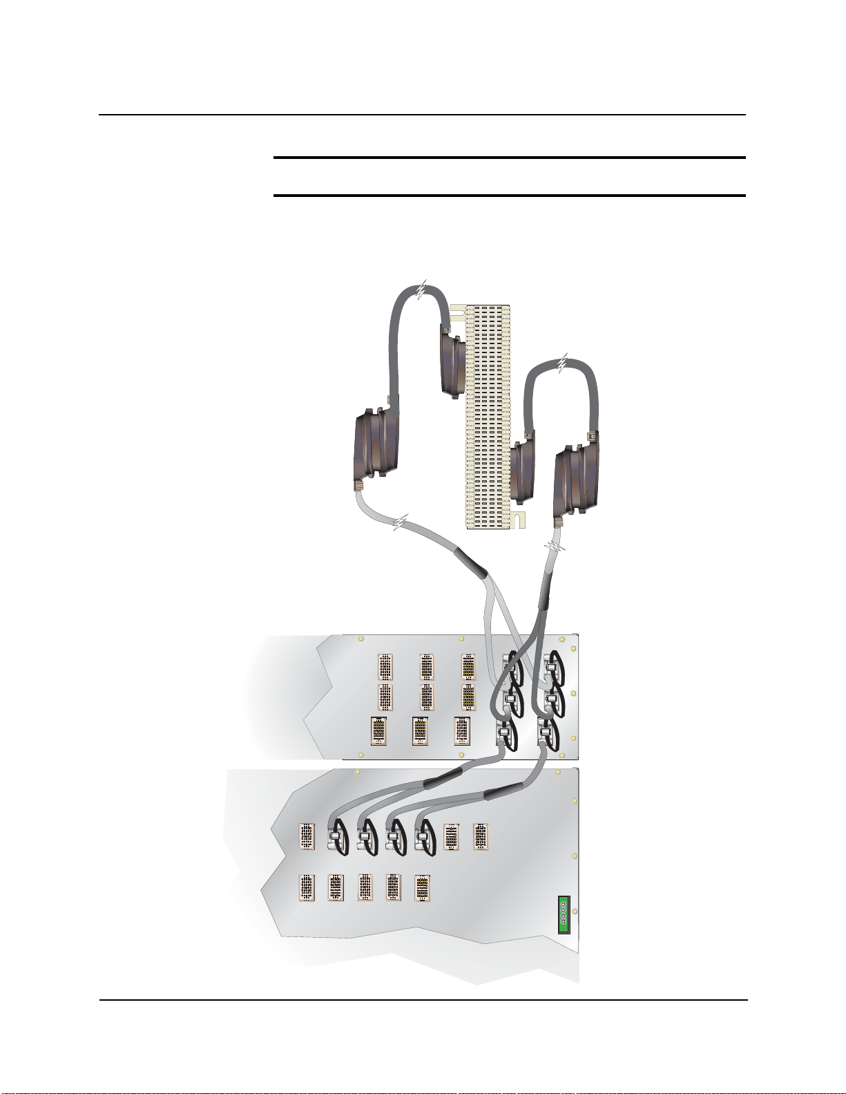
2. BitStorm 1900 Installation and Testing
Step Procedure (continued)
Figure 2-12: Line/CPE and Voice Connections on the Filter Shelf for 10306 Modem Cards
Amp Champ to
Dual Omni Grid Cable
part # 04-00007-10
Interconnect
Cable #1 IN
*Not Used
J2J2 J3J3
Interconnect
Cable #1 OUT
J1J2
J1J2
J1J1
Omni Grid to
Dual Omni Grid
Cable part #
04-00028-01
Dial T one IN
from PBX/PSTN
Dial T one &
EtherLoop OUT
EtherLoop
from BitStorm shelf
02-17184
1900-A2-GN20-00 BitStorm 1900 Installation and Maintenance Guide 2-61
Page 78

2. BitStorm 1900 Installation and Testing
Step Procedure (continued)
Figure 2-13: Line/CPE and Voice Connections on the Filter Shelf for 10224 Modem Cards
Dial T one IN
from PBX/PSTN
Dial T one &
EtherLoop OUT
EtherLoop
from BitStorm shelf
J2
J2
*Not Used
Amp Champ to
Dual Omni Grid Cable
part # 04-00007-10
J2
J2
J1
J1
J1
J1
Omni Grid to
Omni Grid Cable
part # 04-00008-18
Male
Female
Male
Interconnect
Cable #1 IN
Interconnect
Cable #1 OUT
02-17185
2-62 BitStorm 1900 Installation and Maintenance Guide 1900-A2-GN20-00
Page 79

2. BitStorm 1900 Installation and Testing
STOP
Step Procedure (continued)
8.) Go to "Task 011: Installing External Voice Switch Connections, on
page 70."
<RXKDYHFRPSOHWHGWKLVWDVN
1900-A2-GN20-00 BitStorm 1900 Installation and Maintenance Guide 2-63
Page 80

2. BitStorm 1900 Installation and Testing
Task 009: Installing Voice/Data w/Filter 66-Block
Connections
Use this procedure to connect the BitStorm 1900 to the EtherLoop
cross-connect in applications where voice/data service is required with
a Filter 66-Block.
Requirements
This procedure requires the following tools and materials:
• 5 BitStorm 1900 cable harnesses
• 5 intermediate cables
• Cross-connect block(s) of the same type used in the existing main
distribution frame (MDF)
• Cross-connect punch-down tool
• Jumper Wire (24 AWG)
"Appendix B. Cabling Specifications," on page 115 contains the
complete specifications for the cables and wiring required in this
procedure.
Step Procedure
1.) Mount 66-blocks on wall in an appropriate area for running
jumpers.
2.) Verify the room position on frame blocks.
3.) Replace jumpers to 66-Filter Block and retest phone lines.
4.) Refer to Figure 2-14, "Voice/Data Filter 66-Block Connections for
10306 CO Modems," on page 65, and Figure 2-15, "Voice/Data
Filter 66-Block Connections for 10224 CO Modems," on page 66.
2-64 BitStorm 1900 Installation and Maintenance Guide 1900-A2-GN20-00
Page 81

2. BitStorm 1900 Installation and Testing
Step Procedure (continued)
Figure 2-14: Voice/Data Filter 66-Block Connections for 10306 CO Modems
Amp Champ to Dual Amp
Champ Cable
part # 04-00029-01
Amp Champ to
Dual Omni Grid Cable
part # 04-00007-10
*Not Used
J1J2J1J2
02-17186
1900-A2-GN20-00 BitStorm 1900 Installation and Maintenance Guide 2-65
Page 82

2. BitStorm 1900 Installation and Testing
STOP
Step Procedure (continued)
Figure 2-15: Voice/Data Filter 66-Block Connections for 10224 CO Modems
Amp Champ to
Dual Omni Grid Cable
part # 04-00007-10
*Not Used
J1
J2
<RXKDYHFRPSOHWHGWKLVWDVN
02-17187
2-66 BitStorm 1900 Installation and Maintenance Guide 1900-A2-GN20-00
Page 83

2. BitStorm 1900 Installation and Testing
Task 010: Installing the Data-only Connections
Use this procedure to connect the BitStorm 1900 to the EtherLoop
cross-connect in applications where no voice service is required.
Requirements
This procedure requires the following tools and materials:
• 5 BitStorm 1900 cable harnesses
• 5 intermediate cables
• Cross-connect block(s) of the same type used in the existing main
distribution frame (MDF)
• Cross-connect punch-down tool
"Appendix B. Cabling Specifications," on page 115 contains the
complete specifications for the cables and wiring required in this
procedure.
Step Procedure
1.) Place and secure the dedicated EtherLoop cross-connect on the
facility main distribution frame.
2.) Route the Tip/Ring pairs originating from the StormPort/CPE lines
to the EtherLoop cross-connect.
3.) Te rmin ate the StormPort /CPE Tip/Ring connections to the
EtherLoop cross-connect block. Record the StormPort/CPE Tip/
Ring assignments of the EtherLoop cross-connect according to
local office procedures.
4.) Connect one Amp-Champ connector of an intermediate cable to
the matching connector on the EtherLoop cross-connect block,
then route the other connector to the equipment bay containing the
BitStorm 1900.
5.) Connect the J1/J2 split connectors on the cable harness to the
matching J1/J2 modem connectors of two adjacent modem cards
in the BitStorm 1900 shelf. Refer to Figure 2-16, "Data-only Con-
nections on the 66-Block for 10306 CO Modem Cards," on page
68, and/or
1900-A2-GN20-00 BitStorm 1900 Installation and Maintenance Guide 2-67
Page 84

2. BitStorm 1900 Installation and Testing
Step Procedure (continued)
Figure 2-16: Data-only Connections on the 66-Block for 10306 CO Modem Cards
Figure 2-17, "Data-only Connections on the 66-Block for 10224 CO
Modem Cards," on page 69. Record the EtherLoop assignments.
Amp Champ to Dual Amp
Champ Cable
part # 04-00029-01
J1J2
Female
Male
J1J2
Female
Male
*Not Used
Male
Amp Champ to
Dual Omni Grid Cable
part # 04-00007-10
02-17188
2-68 BitStorm 1900 Installation and Maintenance Guide 1900-A2-GN20-00
Page 85

2. BitStorm 1900 Installation and Testing
STOP
Step Procedure (continued)
Figure 2-17: Data-only Connections on the 66-Block for 10224 CO Modem Cards
Female
Male
Male
J1
J2
Amp Champ to
Dual Omni Grid Cable
part # 04-00007-10
*Not Used
02-17189
<RXKDYHFRPSOHWHGWKLVWDVN
1900-A2-GN20-00 BitStorm 1900 Installation and Maintenance Guide 2-69
Page 86

2. BitStorm 1900 Installation and Testing
Task 011: Installing External Voice Switch
Connections
Use this procedure to connect the BitStorm 1900 lines to an external
voice facility.
Requirements
This procedure requires the following tools and materials:
• 24 jumper wires (24-AWG) for each BitStorm 1900 modem card
installed (240 wires for a full shelf)
• Cross-connect punch-down tool
"Appendix B. Cabling Specifications," on page 115 contains the
specifications for the cables and wiring required in this procedure.
Step Procedure
1.) Identify the existing Tip and Ring jumper connections from the
external voice facility cross-connect block to the customerpremises equipment (CPE) cross-connect block.
2.) Verify dial tone on the existing voice facility at the CPE crossconnect block for the line being rerouted.
3.) Remove the Tip and Ring jumper connections from the line.
4.) Terminate the Tip/Ring jumper wires from the cross-connect of the
external voice facility to the "Voice" side of the EtherLoop crossconnect.
5.) Terminate the jumper wires from the CPE Tip/Ring connections to
the "EtherLoop" side of the cross-connect block.
6.) Verify the new connection by testing dial tone again at the CPE
cross-connect block.
7.) Secure all cabling in accordance with local office procedures.
2-70 BitStorm 1900 Installation and Maintenance Guide 1900-A2-GN20-00
Page 87

2. BitStorm 1900 Installation and Testing
STOP
Step Procedure (continued)
8.) Record the EtherLoop cross-connect Tip/Ring assignments for the
voice facility according to local office procedures.
<RXKDYHFRPSOHWHGWKLVWDVN
1900-A2-GN20-00 BitStorm 1900 Installation and Maintenance Guide 2-71
Page 88

2. BitStorm 1900 Installation and Testing
Task 012: Configuring the MIU
Complete the following steps to configure the MIU.
Step Procedure
1.) Ensure that the BitStorm 1900 is powered on.
2.) Verify the PC has an ASCII terminal emulator loaded
(i.e., Hyperterminal software, etc.).
3.) Connect the PC to the MIU card using the MIU Craft Cable
(RS-232 to RJ-11 adapter and telephone cable) as shown in
Figure 2-18, "Craft Connection with the MIU Craft Cable," on page
73.
a.) Connect the DB-9 end of the cable to the serial COM port on
the PC.
b.) Connect the RJ-11 connector to the RS-232 jack on the MIU
card.
2-72 BitStorm 1900 Installation and Maintenance Guide 1900-A2-GN20-00
Page 89

2. BitStorm 1900 Installation and Testing
Step Procedure (continued)
Figure 2-18: Craft Connection with the MIU Craft Cable
CRAFT Connection
MIU Card
MIU Craft Cable
(DB-9 with
RJ-11 to RS-232
adapter)
Craft Terminal
02-17190
1900-A2-GN20-00 BitStorm 1900 Installation and Maintenance Guide 2-73
Page 90

2. BitStorm 1900 Installation and Testing
Step Procedure (continued)
4.) Set the serial COM1 port terminal communication settings.
a.) Initiate a Terminal Session using terminal emulation software
(i.e., Hyperterminal).
b.) Select the appropriate serial
menu (i.e., COM1, COM2, etc).
c.) Verify the port settings are the same as shown in Figure 2-19,
"COM Port Settings." and click
Figure 2-19: COM Port Settings
COM port from the pull down
OK.
2-74 BitStorm 1900 Installation and Maintenance Guide 1900-A2-GN20-00
Page 91

2. BitStorm 1900 Installation and Testing
Step Procedure (continued)
5.) The Craft Interface Login screen displays. Type
admin for the default Username and press <Enter>.
NOTE: The Craft Interface is case-sensitive. Make sure to type all entries in
lowercase.
The following screen displays requiring a Password to continue:
6.) Type
etherloop and press <Enter>. (The user name
and password can be changed after the initial login).
1900-A2-GN20-00 BitStorm 1900 Installation and Maintenance Guide 2-75
Page 92

2. BitStorm 1900 Installation and Testing
Step Procedure (continued)
The BS1900MIU>> prompt displays:
7.) For list of all available CLI commands, type
BS1900MIU>> prompt and press <Enter>.
This screen provides a list of the available commands to configure
the MIU. Refer to the following table for a description of each command.
Table 2-3: CLI (Command Line Interface) Commands
help at the
CLI Commands
Command Description
CLEAR Enter to clear the screen of data leaving only the
BS1900MIU>> prompt.
CLS This command is the same as CLEAR.
2-76 BitStorm 1900 Installation and Maintenance Guide 1900-A2-GN20-00
Page 93

2. BitStorm 1900 Installation and Testing
Table 2-3: CLI (Command Line Interface) Commands
CLI Commands
Command Description
DATE Enter to change the date.
HELP Enter to obtain additional help
IFCONFIG Use to configure the MIU I.P. Address, Subnet Mask, Status,
Default Gateway etc.
MENU Enter to view the Main Menu for the interface.
1900-A2-GN20-00 BitStorm 1900 Installation and Maintenance Guide 2-77
Page 94

2. BitStorm 1900 Installation and Testing
Command Description
RESET Use to Reset or Reboot the system.
Table 2-3: CLI (Command Line Interface) Commands
CLI Commands
PING Enter to verify if an I.P. Address is valid.
(It is not advised to power down the system in order to perform
a reset of the system.)
SNMP Enter to review and/or modify the current SNMP configuration.
SYSINFO Enter to access and review system information.
TIME Enter to set the time.
VERSION Enter to view the version of firmware currently loaded on the
MIU.
2-78 BitStorm 1900 Installation and Maintenance Guide 1900-A2-GN20-00
Page 95

2. BitStorm 1900 Installation and Testing
Step Procedure (continued)
8.) Type menu at the BS1900MIU>> prompt.
The
Menu displays.
9.) Type
BitStorm 1900 MIU Craft Interface Main
a to select Configuration.
1900-A2-GN20-00 BitStorm 1900 Installation and Maintenance Guide 2-79
Page 96

2. BitStorm 1900 Installation and Testing
Step Procedure (continued)
10.) From the Configuration Menu, type a to access the
Network Interface Configuration screen.
11.)
Type in the
Ethernet Subnet Mask
Gateway,
to save the settings, then press
MIU Ethernet IP Ad dress, MIU
, MIU Default
and the
MIU Sh elf ID
<Esc>
. The
.
<CTRL>+W
Press
Configuration Menu will display.
2-80 BitStorm 1900 Installation and Maintenance Guide 1900-A2-GN20-00
Page 97

2. BitStorm 1900 Installation and Testing
Step Procedure (continued)
12.) Type c to select Set Time-of-Day Clock. The following
screen appears:
13.) Enter the current date and time.
a.) Enter the current date in the format MMDDYYYY. [Enter only
the numbers not the slashes (/). This screen is currently under
construction. There will be a 0 and an f in place of the slash (/)
between the numbers.]
1900-A2-GN20-00 BitStorm 1900 Installation and Maintenance Guide 2-81
Page 98

2. BitStorm 1900 Installation and Testing
Step Procedure (continued)
b.) After entering the 4-digit year, the cursor will automatically
jump to the Time field. (This field is not marked in this version.)
Enter the time as HHMMSS (Do not type the colon (:) between
the numbers, plus signs (+) will separate the numbers.
c.) Press
<CTRL>+W to save the changes. Press <Esc> or
<CTRL>+C to return to the Configuration screen,
then press
<Esc> or <CTRL>+C again to return to the
Main Menu screen.
14.) To change user name and password settings, type
User Account Administration.
d to select
2-82 BitStorm 1900 Installation and Maintenance Guide 1900-A2-GN20-00
Page 99

2. BitStorm 1900 Installation and Testing
Step Procedure (continued)
15.) Type a to select Change Username to modify the user
name. The following screens display:
1900-A2-GN20-00 BitStorm 1900 Installation and Maintenance Guide 2-83
Page 100

2. BitStorm 1900 Installation and Testing
Step Procedure (continued)
16.) Type a new user name, then press <Enter> (a confirmation will
follow indicating that the user name has been saved). Press any
key to return to the
screen.
User Account Administration
17.) Select
following screens display:
Change Password to modify the password. The
18.) Type a new password, then press
password when prompted. A confirmation will follow indicating that
the password has been saved. Press any key to return to the Main
Menu screen.
2-84 BitStorm 1900 Installation and Maintenance Guide 1900-A2-GN20-00
<Enter>. Re-enter the
 Loading...