

Paradyne iMarc SLV9128 Installation Instructions Manual

iMarc™ SLV 9128
Network Access Module (NAM)
NOTE: The FrameSaver®
product line has been
renamed to iMarc.
Installation Instructions
Document Number 9128-A2-GN11-70
May 2003
Contents
Product Documentation Online ..................................................................... 2
Upgrading a Unit to the SLM Feature Set ..................................................... 2
Package Checklist ........................................................................................ 2
Preparation ................................................................................................... 3
Cables You May Need to Order .................................................................... 3
Safety Instructions ........................................................................................ 3
Installing the I/O Card ................................................................................... 4
Installing the NAM into a Multislot Housing .................................................. 6
Connecting the COM Port to an Asynchronous Terminal ............................. 7
Verifying that Self-Test Passed ..................................................................... 7
Menu Hierarchy ............................................................................................ 8
A Quick Guide to Configuration .................................................................... 11
About the Installation Procedures ................................................................. 12
Full Installation and Setup ............................................................................ 12
Minimal Installation for Service Providers ..................................................... 15
Setting Up Local Management at the Central Site ........................................ 17
Automatic Configuration ............................................................................... 18
Setting Up the Modem .................................................................................. 18
Setting Up the ISDN DBM ............................................................................ 20
Configuring SNMP Trap Managers and Trap Dial-Out ................................. 22
Connecting to the Network ........................................................................... 22
Verifying the End-to-End Path ...................................................................... 24
Connecting to ISDN ...................................................................................... 25
Connecting the Modem ................................................................................. 25
Connecting to DSX ...................................................................................... 25
Connecting to Ethernet ................................................................................. 26
Connecting to a DTE .................................................................................... 26
Verifying Connections and Setup .................................................................. 27
Connecting the COM Port to the Router ....................................................... 30
Important Safety Instructions ........................................................................ 31
EMI Notices .................................................................................................. 33
Government Requirements ........................................................................... 33
Warranty, Sales, Service, and Training Information ...................................... 36
1

Document Feedback ..................................................................................... 36
Trademarks ................................................................................................... 36
Patent Notification ......................................................................................... 36
Product Documentation Online
Complete documentation for this product is available at www.paradyne.com.
Select Support → Technical Manuals → iMarc IP/Frame Relay Devices.
Select the following documents:
iMarc SLV Technical Description (9000-A2-GB30)
iMarc SLV Configuration Reference (9000-A2-GB31)
iMarc SLV SNMP Reference (9000-A2-GB32)
iMarc SLV Operations Guide (9000-A2-GB33)
To order a paper copy of a Paradyne document, or to speak with a sales representative,
please call 1-727-530-2000.
Upgrading a Unit to the SLM Feature Set
Full Service Level Management (SLM) capability can be activated in units that have the
basic diagnostic feature set at any time. This is an optional feature that adds real-time
and historical network performance monitoring and SLA (Service Level Agreement)
reporting capabilities to your iMarc unit and network. Simply order a Feature Activation
Certificate and provide the model to be activated, your OpenLane
key number, and the number of iMarc units to be activated to SLM capability. You can
order the certificate for a single unit or for many units.
®
SLM system license
OpenLane SLM Release 5.3 or above is required to schedule activation of SLM features
in units, and to manage the number of activations remaining on the certificate.
OpenLane also provides a Certificate Summary Report to assist you in the management
of the certificate.
When the Feature Activation Certificate arrives, add the Activation Certificate Number to
your OpenLane SLM application’s database. Activations can occur at any time, for as
many units as desired, until no activations remain for the certificate. When ready to
activate units, simply select the units to be activated and schedule the activations. The
activations occur when scheduled, and OpenLane updates the certificate information.
Contact your sales representative for additional information.
Package Checklist
Verify that your package contains the following:
❑ iMarc SLV NAM
❑ NAM I/O card
❑ T1 network cable
Be sure to register your warranty at www.paradyne.com/warranty.
2

Preparation
Make sure you have:
❑ A small flat-blade screwdriver.
❑ A small Phillips screwdriver.
❑ iMarc SLV ISDN Dial Backup Module (DBM) Installation Instructions (Document
No. 9000-A2-GN19) if installing an ISDN PRI DBM.
If an iMarc NAM with DBM is being replaced, the DBM must be transferred to the
replacement NAM.
❑ If desired, an operable Ethernet LAN (Local Area Network) connection for access
by an NMS (Network Management System)
❑ Configuration information for the iMarc unit being installed or replaced.
❑ Appropriate cables:
— DSX cable
— Data port cables
— COM port-to-terminal or COM port-to-PC cable
— Modem cable
— ISDN PRI cable, if applicable
— Ethernet cable, if applicable
See the appropriate manual for additional information.
For troubleshooting, see the iMarc SLV Operations Guide
For technical specifications, and connectors, cables, and pin assignments, see the
iMarc SLV Technical Description
Cables You May Need to Order
Feature
If connecting to a . . . Order a . . .
T1 line interface/connector
(For use in Canada)
DSX-1 Cable DSX-1 Adapter Cable
T1 line interface cable,
RJ48C-to-CA81A
8-Pin modular plug-to-DB15 socket
Number
3100-F1-510
9008-F1-560
Contact your sales representative to order cables.
Safety Instructions
Please read the Important Safety Instructions on page 30.
3
HANDLING PRECAUTIONS FOR STATIC-SENSITIVE DEVICES
!
This product is designed to protect sensitive components from
damage due to electrostatic discharge (ESD) during normal
operation. When performing installation procedures,
however, take proper static control precautions to
prevent damage to equipment. If you are not sure
of the proper static control precautions, contact
your nearest sales or service representative.
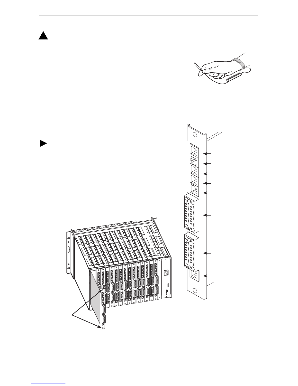
Installing the I/O Card
The NAM’s I/O card provides the network, DSX, DBM,
modem, DTE, and COM port connections. The I/O card
inserts directly behind the NAM that it supports in the
access carrier.
Procedure
1. Remove the I/O card from the shipping box.
To avoid damaging the card, handle by the top and
bottom edges only.
2. At the rear of the carrier, align the I/O card with the
upper and lower tracks for the slot.
Push gently toward the midplane until it stops and
the card cannot be pushed any further.
NAM
I/O Card
SINGLE
T1 NAM
N
E
T
1
D
B
M
M
D
M
D
S
X
E
N
E
T
P
O
R
T
1
Network
ISDN DBM
Modem
DSX-1
Ethernet
Por t 1
Captive
Screws
3. Using a small Phillips screwdriver, alternately tighten the captive screws until they
are all snug.
Rear View
00-16835
4
P
O
Por t 2
R
T
2
Communications
C
O
Por t
M
00-16834

Installing the NAM into a Multislot Housing
The illustration shows the 14-slot access carrier housing.
CAUTION:
Be sure that you install the NAM in the correct slot so that it mates with its
matching I/O card. Otherwise, you could damage your card.
Procedure
1. Remove the NAM from the shipping
box. Handle only by the top and
bottom edges to avoid damaging the
card.
2. At the front of the carrier, align the
NAM with the upper and lower tracks
of the appropriate slot.
3. Slide the NAM into the tracks until it
seats with the midplane connectors.
Use care not to force the card or
bend any pins.
4. Close the carrier’s upper and lower
ejector latches to lock the card into
place, then tighten the captive
screws on the ejector latches.
5. Check that the OK LED lights.
If the OK LED is on, you have power.
If not, refer to Troubleshooting in the
iMarc SLV Operations Guide for possible explanations.
Ejector
Latches
Front View
98-16209
5

Connecting the COM Port to an Asynchronous Terminal
A VT100-compatible asynchronous terminal or a PC providing VT100 terminal
emulation must be used to set up access to and management of the unit.
Procedure
1. Configure the VT100-compatible asynchronous terminal or PC to be compatible
with the iMarc unit:
— COM Port in use by your PC is COM1 or COM2.
— COM Port Baud Rate is set to 19.2 Kbps.
— Character length is set to 8 data bits.
— Parity is set to None.
— Stop bit is set to 1.
— Flow Control is set to None.
2. Insert the 8-pin end of the cable into the COM port for the appropriate slot.
COM Port-to-Terminal/Printer
or
COM Port-to-PC Cable
P
O
R
T
2
C
O
M
COM
98-16208a
3. Insert the other end of the cable into the terminal or PC.
4. Press Enter on the keyboard to display the Main Menu.
If the Main Menu does not appear, recheck the terminal or PC settings (see Step 1),
or press the Enter key. Refer to Troubleshooting in the iMarc SLV Operations Guide
for other possible explanations.
Verifying that Self-Test Passed
To verify that the unit passed its self-test, go to the System and Test Status screen.
Main Menu → Status → System and Test Status
The results of the self-test appears on the next screen line, under the screen title.
If any failure messages appear, reset the unit by disconnecting, then reconnecting the
power cord. The unit will perform the self-test again. If the failure reappears, call your
service representative for assistance.
6

Menu Hierarchy
The Menu Hierarchy shows the organization of the iMarc unit’s screens.
S ta t u s
System and Test
Status
LMI Reported DLCIs DLCI
IP Path Connection
Status
PVC Connection
Status
Timeslot
Assignment Status
DBM Interface
Status
Self-Test Results
Last System Reset
Health and Status
Te s t St at u s
Status
CIR (bps)
Device Name
IP Address
Status
Discovery Source
Source Link, DLCI, EDLCI
Primary Destination Status
Alternate Destination Status
Network Timeslot Status
DSX-1 Timeslot Status
Line Status
Link
Link Operating Mode
Call Status
Maximum Link Rate
Negotiated Rate
ISDN Channel
I P R o u t i n g T a b l e Destination
Mask
Gateway
Hop
Type
Interface
TTL
Performance
Statistics
T r a p E v e n t L o g Number of Trap Events
Display LEDs and Control Leads
I d e nt i t y System
Service Level Verification
DLCI
Frame Relay
ESF Line
DBM Call
Ethernet
Clear All Statistics
Time of Day
Event
DBM
NAM
7

Te st
Network PVC Tests
Data Port PVC Tests
ISDN Call/PVC Tests
PVC Loopback
Pattern Tests
Connectivity (ISDN only)
Configuration
Network Physical
Tests
PRI Physical Tests
Data Port Physical
Tests
DSX-1 Physical
Tests
IP Ping
Lamp Test
Abort All Tests
System Frame Relay and LMI
Network Physical
DSX-1 Interface Status
Local Loopbacks
Remote Loopback
Pattern Tests
DTE Loopback
Local Loopbacks
Pattern Tests
Class of Service Definitions
Service Level Verification
General
Frame Relay
DLCI Records
Line Framing Format
Line Coding Format
Line Equalization
Send All Ones
Data Ports Physical
Time Slot
Assignments
PVC Connections Source Link, DLCI, EDLCI
IP Path List Add and Display Static Paths
Frame Relay
DLCI Records
Frame Relay Network Assignments
DSX-1 to Network Assignments
Sync Data Port Assignments
Clear Assignments
Primary Destination Link, DLCI, EDLCI
Alternate Destination Link, DLCI,
EDLCI
8

Management and
Communication
Options
Node IP
Management PVCs
General SNMP Management
Telnet and FTP Sessions
SNMP NMS Security
SNMP Traps
Ethernet Management
Communication Port
Modem Port
AutoConfiguration
Control
Frame Relay Discovery Mode
Automatic Circuit Removal
Modem Call
Directories
System Information Device Name
Administer Logins Login ID
Change Operating
Mode
Select Software
Release
Select DSX/PRI LED
Source
LMI Packet Capture
Utility
Directory Number
Directory Phone Number
System Name, Location, Contact
Date
Time
Password
Access Level
Back-to-Back Mode
Standard Mode
Current Release
Alternate Release
Switch & Reset
Capture Interface
Packet Capture Start/Stop
Status
Packets in Buffer
Display LMI Trace Log
Disconnect Modem
Reset Device
Easy Install
Service Type
Node IP Address
Node Subnet Mask
TS Access
Create Dedicated Network Mgmt Link
Ethernet Port Options Screen
Time Slot Assignment Screen
Network 1 Line Framing Format
Network 1 Line Coding Format
Network 1 Line Build Out
9

A Quick Guide to Configuration
The iMarc unit should operate using the default (factory-set) configuration options, with
exception to the changes specified in these installation instructions. Refer to the
following table for help in navigating the menus.
Press the . . . To . . .
Esc key Go back one screen or menu level. To see a visual
representation of the menu levels, see Menu Hierarchy on
page 7.
Tab key, or
Up (↑), Down (↓),
Left (←) and Right (→)
Arrow keys
Enter or Return key Complete the menu or option selection.
Spacebar Display the next available setting when changing a
As an example, follow these steps to go to the Configuration Edit/Display menu so you
can start setting up the unit.
To load a configuration for editing:
1. From the Main Menu, press the down arrow key twice so the cursor is on
Configuration.
2. Press Enter to display the Configuration menu. The Load Configuration From menu
appears.
3. Press Enter to select Current Configuration (the cursor is already on this selection).
The Configuration Edit/Display menu appears.
Move the cursor from one menu item to the next.
configuration option. All the available settings for an option
appears at the bottom of the screen.
This sequence of steps would be shown as the menu selection sequence:
Main Menu →Configuration
To save a configuration option change:
1. Press Ctrl-a to switch to the function keys area at the bottom of the screen.
2. Type s or S (S
3. Press Enter again to save your changes to the Current Configuration.
4. Press Esc until the Configuration Edit/Display menu reappears to continue
configuring the unit.
Press Ctrl-a, type m (M
In the sections that follow, only the minimum option changes required are included so
you will have a quick and trouble-free installation. See the configuration option tables in
the iMarc SLV Configuration Reference for more information.
ave) and press Enter. The Save Configuration To menu appears.
ainMenu), and press Enter to return to the Main Menu.
10

There are two methods for installing and setting up the iMarc unit.
One person can install and set up the unit. If this is the case, see Full Installation
and Setup.
An installer can physically install and set up access to the unit, and the network
operation center (NOC) can complete the setup. If this is the case, see Minimal
Installation for Service Providers on page 14.
Certain procedures are common to both the full installation and minimal methods. These
procedures are referenced in the full and minimal installation instructions (starting with
Setting Up Local Management at the Central Site on page 16). Refer to them, as
needed.
Full Installation and Setup
An Easy Install screen is provided to simplify installation and setup. It can be used for
the first part of the installation when one person is installing and setting up the unit from
beginning to end.
Easy Install Screen Example
main/easy_install 9128-II
Device Name: Node A 12/18/2002 23:32
EASY INSTALL
Service Type Frame Relay
Node IP Address: 000.000.000.000 Clear
Node Subnet Mask: 000.000.000.000
TS Access: DLCI
Create a Dedicated Network Management Link
Ethernet Port Options Screen *
Time Slot Assignment Screen
Network 1 Line Framing Format: ESF
Network 1 Line Build Out (LBO): 0.0
Network 1 Line Coding Format: B8ZS
----------------------------------------------------------------------------Ctrl-a to access these functions, ESC for previous menu M
ave
S
980
Clear
ainMenu Exit
11
 Loading...