

Page 1

iMarc™ SLV
Operations Guide
Document No. 9000-A2-GB33-20
May 2003
Page 2

Copyright © 2003 Paradyne Corporation.
All rights reserved.
Printed in U.S.A.
Notice
This publication is protected by federal copyright law. No part of this publication may be copied or distributed,
transmitted, transcribed, stored in a retrieval system, or translated into any human or computer language in any form or
by any means, electronic, mechanical, magnetic, manual or otherwise, or disclosed to third parties without the express
written permission of Paradyne Corporation, 8545 126th Ave. N., Largo, FL 33773.
Paradyne Corporation makes no representation or warranties with respect to the contents hereof and specifically
disclaims any implied warranties of merchantability or fitness for a particular purpose. Further, Paradyne Corporation
reserves the right to revise this publication and to make changes from time to time in the contents hereof without
obligation of Paradyne Corporation to notify any person of such revision or changes.
Changes and enhancements to the product and to the information herein will be documented and issued as a new
release to this manual.
Warranty, Sales, Service, and Training Information
Contact your local sales representative, service representative, or distributor directly for any help needed. For additional
information concerning warranty, sales, service, repair, installation, documentation, training, distributor locations, or
Paradyne worldwide office locations, use one of the following methods:
Internet: Visit the Paradyne World Wide Web site at www.paradyne.com. (Be sure to register your warranty at
www.paradyne.com/warranty.)
Telephone: Call our automated system to receive current information by fax or to speak with a company
representative.
— Within the U.S.A., call 1-800-870-2221
— Outside the U.S.A., call 1-727-530-2340
Document Feedback
We welcome your comments and suggestions about this document. Please mail them to Technical Publications,
Paradyne Corporation, 8545 126th Ave. N., Largo, FL 33773, or send e-mail to userdoc@paradyne.com. Include the
number and title of this document in your correspondence. Please include your name and phone number if you are
willing to provide additional clarification.
Trade mar ks
ACCULINK, COMSPHERE, FrameSaver, Hotwire, MVL, NextEDGE, OpenLane, and Performance Wizard are
registered trademarks of Paradyne Corporation. GranDSLAM, GrandVIEW, iMarc, ReachDSL, and TruePut are
trademarks of Paradyne Corporation. All other products and services mentioned herein are the trademarks, service
marks, registered trademarks, or registered service marks of their respective owners.
Patent Notification
iMarc products are protected by U.S. Patents: 5,550,700 and 5,654,966. Other patents are pending.
A May 2003 9000-A2-GB33-20
Page 3

Contents
About This Guide
Purpose and Intended Audience . . . . . . . . . . . . . . . . . . . . . . . . . . . . . v
Document Organization . . . . . . . . . . . . . . . . . . . . . . . . . . . . . . . . . . . . v
Product-Related Documents . . . . . . . . . . . . . . . . . . . . . . . . . . . . . . . . vi
Conventions Used . . . . . . . . . . . . . . . . . . . . . . . . . . . . . . . . . . . . . . . . viii
1 User Interface and Basic Operation
Logging In . . . . . . . . . . . . . . . . . . . . . . . . . . . . . . . . . . . . . . . . . . . . . . 1-2
Main Menu . . . . . . . . . . . . . . . . . . . . . . . . . . . . . . . . . . . . . . . . . . . . . . 1-4
Screen Work Areas . . . . . . . . . . . . . . . . . . . . . . . . . . . . . . . . . . . . . . . 1-5
Navigating the Screens . . . . . . . . . . . . . . . . . . . . . . . . . . . . . . . . . . . . 1-6
Keyboard Keys . . . . . . . . . . . . . . . . . . . . . . . . . . . . . . . . . . . . . . . 1-6
Function Keys . . . . . . . . . . . . . . . . . . . . . . . . . . . . . . . . . . . . . . . . 1-7
Selecting an Entry from a Menu . . . . . . . . . . . . . . . . . . . . . . . . . . 1-8
Switching Between Screen Areas . . . . . . . . . . . . . . . . . . . . . . . . . 1-8
Selecting a Field . . . . . . . . . . . . . . . . . . . . . . . . . . . . . . . . . . . . . . 1-9
Entering Information . . . . . . . . . . . . . . . . . . . . . . . . . . . . . . . . . . . 1-9
Screen Contents . . . . . . . . . . . . . . . . . . . . . . . . . . . . . . . . . . . . . . 1-9
Navigating the Router’s CLI . . . . . . . . . . . . . . . . . . . . . . . . . . . . . . . . . 1-10
CLI Keyboard Keys . . . . . . . . . . . . . . . . . . . . . . . . . . . . . . . . . . . . 1-10
2 Security and Logins
Limiting Access . . . . . . . . . . . . . . . . . . . . . . . . . . . . . . . . . . . . . . . . . . 2-2
Controlling Asynchronous Terminal Access. . . . . . . . . . . . . . . . . . . . . 2-2
Limiting Dial-In Access via the Modem Port. . . . . . . . . . . . . . . . . . . . . 2-4
Controlling ISDN Access . . . . . . . . . . . . . . . . . . . . . . . . . . . . . . . . . . . 2-5
Controlling Telnet or FTP Access . . . . . . . . . . . . . . . . . . . . . . . . . . . . 2-6
9000-A2-GB33-20 May 2003 i
ISDN Call Security . . . . . . . . . . . . . . . . . . . . . . . . . . . . . . . . . . . . . 2-5
Disabling ISDN Access . . . . . . . . . . . . . . . . . . . . . . . . . . . . . . . . . 2-5
Limiting Telnet Access . . . . . . . . . . . . . . . . . . . . . . . . . . . . . . . . . . 2-6
Limiting FTP Access . . . . . . . . . . . . . . . . . . . . . . . . . . . . . . . . . . . 2-7
Limiting Telnet or FTP Access Over the
TS Access Management Link . . . . . . . . . . . . . . . . . . . . . . . . . . . . 2-8
Page 4

Contents
Controlling SNMP Access . . . . . . . . . . . . . . . . . . . . . . . . . . . . . . . . . . 2-9
Disabling SNMP Access . . . . . . . . . . . . . . . . . . . . . . . . . . . . . . . . 2-9
Assigning SNMP Community Names and Access Levels . . . . . . . 2-10
Limiting SNMP Access Through IP Addresses . . . . . . . . . . . . . . . 2-11
Creating a Login . . . . . . . . . . . . . . . . . . . . . . . . . . . . . . . . . . . . . . . . . . 2-12
Modifying a Login . . . . . . . . . . . . . . . . . . . . . . . . . . . . . . . . . . . . . . . . . 2-13
Deleting a Login . . . . . . . . . . . . . . . . . . . . . . . . . . . . . . . . . . . . . . . . . . 2-13
Controlling Router CLI Access . . . . . . . . . . . . . . . . . . . . . . . . . . . . . . . 2-14
Access Levels (Command Modes) . . . . . . . . . . . . . . . . . . . . . . . . 2-14
Changing Access Levels . . . . . . . . . . . . . . . . . . . . . . . . . . . . . . . . 2-15
3 Status and Statistics
Displaying System Information. . . . . . . . . . . . . . . . . . . . . . . . . . . . . . . 3-2
Viewing LEDs and Control Leads . . . . . . . . . . . . . . . . . . . . . . . . . . . . 3-4
LED Descriptions . . . . . . . . . . . . . . . . . . . . . . . . . . . . . . . . . . . . . . 3-15
Power Module LEDs (Models 9520, 9520-ILM, 9820-45M). . . . . . 3-19
Display LEDs and Control Leads Screen Descriptions . . . . . . . . . 3-20
Device Messages . . . . . . . . . . . . . . . . . . . . . . . . . . . . . . . . . . . . . . . . . 3-24
Status Information . . . . . . . . . . . . . . . . . . . . . . . . . . . . . . . . . . . . . . . . 3-30
System and Test Status Messages . . . . . . . . . . . . . . . . . . . . . . . . 3-31
Network LMI-Reported DLCIs Status . . . . . . . . . . . . . . . . . . . . . . 3-41
IP Path Connection Status. . . . . . . . . . . . . . . . . . . . . . . . . . . . . . . 3-43
PVC Connection Status . . . . . . . . . . . . . . . . . . . . . . . . . . . . . . . . . 3-45
Time Slot Assignment Status. . . . . . . . . . . . . . . . . . . . . . . . . . . . . 3-48
DBM Interface Status. . . . . . . . . . . . . . . . . . . . . . . . . . . . . . . . . . . 3-50
IP Routing Table . . . . . . . . . . . . . . . . . . . . . . . . . . . . . . . . . . . . . . . . . 3-60
Performance Statistics . . . . . . . . . . . . . . . . . . . . . . . . . . . . . . . . . . . . . 3-62
Clearing Performance Statistics . . . . . . . . . . . . . . . . . . . . . . . . . . 3-63
Service Level Verification Performance Statistics . . . . . . . . . . . . . 3-64
DLCI Performance Statistics . . . . . . . . . . . . . . . . . . . . . . . . . . . . . 3-69
Additional Performance Statistics for IP Enabled DLCI . . . . . . . . . 3-71
Frame Relay Performance Statistics . . . . . . . . . . . . . . . . . . . . . . . 3-72
PPP Performance Statistics. . . . . . . . . . . . . . . . . . . . . . . . . . . . . . 3-76
ATM Performance Statistics (9783, 9788) . . . . . . . . . . . . . . . . . . . 3-78
VCC Performance Statistics (9783, 9788) . . . . . . . . . . . . . . . . . . . 3-79
ESF Line Performance Statistics (9123, 9126, 9128) . . . . . . . . . . 3-81
DDS Line Performance Statistics (9623, 9626) . . . . . . . . . . . . . . . 3-84
T3 Network Line Performance Statistics (9520, 9520-ILM) . . . . . . 3-85
SHDSL Line Performance Statistics (9788). . . . . . . . . . . . . . . . . . 3-88
DBM Call Performance Statistics. . . . . . . . . . . . . . . . . . . . . . . . . . 3-89
Ethernet Performance Statistics . . . . . . . . . . . . . . . . . . . . . . . . . . 3-90
Trap Event Log. . . . . . . . . . . . . . . . . . . . . . . . . . . . . . . . . . . . . . . . . . . 3-91
ii May 2003 9000-A2-GB33-20
Page 5

4 Operation and Maintenance
Modem Operation . . . . . . . . . . . . . . . . . . . . . . . . . . . . . . . . . . . . . . . . 4-2
Activating the Modem PassThru Feature . . . . . . . . . . . . . . . . . . . 4-2
Canceling Modem PassThru Operation. . . . . . . . . . . . . . . . . . . . . 4-2
Manually Disconnecting the Modem . . . . . . . . . . . . . . . . . . . . . . . 4-3
Verifying Modem Operation . . . . . . . . . . . . . . . . . . . . . . . . . . . . . . 4-3
ISDN DBM Operation . . . . . . . . . . . . . . . . . . . . . . . . . . . . . . . . . . . . . . 4-4
Forcing Backup (Disruptive) . . . . . . . . . . . . . . . . . . . . . . . . . . . . . 4-4
Placing a Test Call (Nondisruptive) . . . . . . . . . . . . . . . . . . . . . . . . 4-5
Verifying ISDN Lines . . . . . . . . . . . . . . . . . . . . . . . . . . . . . . . . . . . 4-6
Verifying That Backup Can Take Place . . . . . . . . . . . . . . . . . . . . . 4-6
FTP File Transfers . . . . . . . . . . . . . . . . . . . . . . . . . . . . . . . . . . . . . . . . 4-7
Upgrading System Software . . . . . . . . . . . . . . . . . . . . . . . . . . . . . 4-9
Upgrading ISDN BRI DBM Software . . . . . . . . . . . . . . . . . . . . . . . 4-10
Determining Whether a Download Is Completed. . . . . . . . . . . . . . 4-11
Changing Software . . . . . . . . . . . . . . . . . . . . . . . . . . . . . . . . . . . . 4-11
Transferring Collected Data . . . . . . . . . . . . . . . . . . . . . . . . . . . . . . 4-12
Turning Off the System Alarm Relay . . . . . . . . . . . . . . . . . . . . . . . . . . 4-13
Hardware Maintenance for Models 9520, 9520-ILM, and 9820-45M . . 4-14
Cleaning the Front Panel Assembly . . . . . . . . . . . . . . . . . . . . . . . 4-14
Replacing the Front Panel Assembly. . . . . . . . . . . . . . . . . . . . . . . 4-15
Replacing a Power Module . . . . . . . . . . . . . . . . . . . . . . . . . . . . . . 4-16
Contents
5Troubleshooting
Problem Indicators . . . . . . . . . . . . . . . . . . . . . . . . . . . . . . . . . . . . . . . . 5-2
Resetting the Unit and Restoring Communication . . . . . . . . . . . . . . . . 5-3
Resetting the Unit from the Control Menu . . . . . . . . . . . . . . . . . . . 5-3
Resetting the Unit By Cycling the Power . . . . . . . . . . . . . . . . . . . . 5-3
Restoring Communication with an Improperly Configured Unit . . . 5-4
Troubleshooting Management Link Feature . . . . . . . . . . . . . . . . . . . . 5-5
LMI Packet Capture Utility Feature . . . . . . . . . . . . . . . . . . . . . . . . . . . 5-5
Viewing Captured Packets from the Menu-Driven User Interface . 5-6
Alarms . . . . . . . . . . . . . . . . . . . . . . . . . . . . . . . . . . . . . . . . . . . . . . . . . 5-7
Viewing the Trap Event Log . . . . . . . . . . . . . . . . . . . . . . . . . . . . . . . . . 5-15
Troubleshooting Tables . . . . . . . . . . . . . . . . . . . . . . . . . . . . . . . . . . . . 5-15
Device Problems . . . . . . . . . . . . . . . . . . . . . . . . . . . . . . . . . . . . . . 5-15
Frame Relay PVC Problems . . . . . . . . . . . . . . . . . . . . . . . . . . . . . 5-17
ISDN DBM Problems . . . . . . . . . . . . . . . . . . . . . . . . . . . . . . . . . . . 5-18
Tests Available . . . . . . . . . . . . . . . . . . . . . . . . . . . . . . . . . . . . . . . . . . . 5-19
Test Timeout Feature . . . . . . . . . . . . . . . . . . . . . . . . . . . . . . . . . . 5-20
DBM Tests . . . . . . . . . . . . . . . . . . . . . . . . . . . . . . . . . . . . . . . . . . . 5-20
9000-A2-GB33-20 May 2003
iii
Page 6

Contents
Starting and Stopping a Test . . . . . . . . . . . . . . . . . . . . . . . . . . . . . . . . 5-21
Aborting All Tests. . . . . . . . . . . . . . . . . . . . . . . . . . . . . . . . . . . . . . 5-22
PVC Tests . . . . . . . . . . . . . . . . . . . . . . . . . . . . . . . . . . . . . . . . . . . . . . 5-23
PVC Loopback. . . . . . . . . . . . . . . . . . . . . . . . . . . . . . . . . . . . . . . . 5-24
Send Pattern . . . . . . . . . . . . . . . . . . . . . . . . . . . . . . . . . . . . . . . . . 5-25
Monitor Pattern . . . . . . . . . . . . . . . . . . . . . . . . . . . . . . . . . . . . . . . 5-25
Connectivity . . . . . . . . . . . . . . . . . . . . . . . . . . . . . . . . . . . . . . . . . . 5-26
Test Call. . . . . . . . . . . . . . . . . . . . . . . . . . . . . . . . . . . . . . . . . . . . . 5-26
Network ATM Loopback (9783, 9788) . . . . . . . . . . . . . . . . . . . . . . . . . 5-27
Physical Tests (9123, 9126, 9128). . . . . . . . . . . . . . . . . . . . . . . . . . . . 5-29
Line Loopback (9123, 9126, 9128) . . . . . . . . . . . . . . . . . . . . . . . . 5-30
Payload Loopback (9123, 9126, 9128) . . . . . . . . . . . . . . . . . . . . . 5-31
Repeater Loopback (9123, 9126, 9128) . . . . . . . . . . . . . . . . . . . . 5-32
DTE Loopback (9123, 9126, 9128) . . . . . . . . . . . . . . . . . . . . . . . . 5-33
Send Line Loopback (9123, 9126, 9128). . . . . . . . . . . . . . . . . . . . 5-34
Data Channel Loopbacks on a Frame Relay Link
(9123, 9126, 9128) . . . . . . . . . . . . . . . . . . . . . . . . . . . . . . . . . . . . 5-35
Send Remote Line Loopback (9123, 9126, 9128) . . . . . . . . . . . . . 5-36
Send and Monitor Pattern Tests (9123, 9126, 9128). . . . . . . . . . . 5-37
Physical Tests (9520, 9520-ILM) . . . . . . . . . . . . . . . . . . . . . . . . . . . . . 5-38
Line Loopback (Network or 9520-ILM T3 User Port) . . . . . . . . . . . 5-40
DTE Loopback (9520 Data Port) . . . . . . . . . . . . . . . . . . . . . . . . . . 5-41
Physical Tests (9623, 9626). . . . . . . . . . . . . . . . . . . . . . . . . . . . . . . . . 5-42
CSU (External) Network Loopback (9623, 9626) . . . . . . . . . . . . . 5-43
DSU (Internal) Network Loopback (9623, 9626) . . . . . . . . . . . . . . 5-43
Latching Loopback (9623, 9626) . . . . . . . . . . . . . . . . . . . . . . . . . . 5-44
Send 511 (9623, 9626) . . . . . . . . . . . . . . . . . . . . . . . . . . . . . . . . . 5-44
Monitor 511 (9623, 9626) . . . . . . . . . . . . . . . . . . . . . . . . . . . . . . . 5-45
DTE Loopback (9623, 9626) . . . . . . . . . . . . . . . . . . . . . . . . . . . . . 5-45
Physical Tests (9720, 9783, 9788 CSU/DSUs) . . . . . . . . . . . . . . . . . . 5-46
DTE Loopback (9720, 9783, 9788 CSU/DSUs). . . . . . . . . . . . . . . 5-46
Physical Tests (9820-2M, 9820-8M, 9820-45M) . . . . . . . . . . . . . . . . . 5-47
DTE Loopback (9820-2M, 9820-8M, 9820-45M) . . . . . . . . . . . . . . 5-47
IP Ping Test . . . . . . . . . . . . . . . . . . . . . . . . . . . . . . . . . . . . . . . . . . . . . 5-48
IP Ping Test – Procedure 1 . . . . . . . . . . . . . . . . . . . . . . . . . . . . . . 5-53
IP Ping Test – Procedure 2 . . . . . . . . . . . . . . . . . . . . . . . . . . . . . . 5-54
Lamp Test . . . . . . . . . . . . . . . . . . . . . . . . . . . . . . . . . . . . . . . . . . . . . . 5-54
Telnet . . . . . . . . . . . . . . . . . . . . . . . . . . . . . . . . . . . . . . . . . . . . . . . . . . 5-55
Index
iv May 2003 9000-A2-GB33-20
Page 7

About This Guide
Purpose and Intended Audience
This document describes the operation and maintenance of the following
iMarc SLV CSU/DSUs and routers: 9123, 9126, 9128 standalone,
9128 carrier-mount, 9520, 9520-ILM, 9623, 9626, 9720, 9783, 9788, 9820-2M,
9820-8M, and 9820-45M.
Features introduced in firmware release 2.1 are described in this manual but may
not be available in all models.
Document Organization
Section Description
Chapter 1, User Interface and
Basic Operation
Chapter 2, Security and Logins Provides procedures for controlling access to the
Chapter 3, Status and Statistics Describes the ways you can determine device and
Chapter 4, Operation and
Maintenance
Chapter 5, Troubleshooting Provides device problem resolution, alarm, and other
Index Lists key terms, acronyms, concepts, and sections.
A master glossary of terms and acronyms used in Paradyne documents is
available on the World Wide Web at www.paradyne.com. Select Support
Technical Manuals →Technical Glossary.
Shows how to navigate the menu-driven user
interface.
iMarc SLV and setting up logins.
network status and obtain statistics.
Describes model-specific operating and maintenance
procedures.
information, as well as troubleshooting and test
procedures.
→
9000-A2-GB33-20 May 2003 v
Page 8

About This Guide
Product-Related Documents
Complete Paradyne documentation for this product is available at
www.paradyne.com. Select Support →Technical Manuals →iMarc IP/Frame
Relay Devices.
Document
Number Document Title
The iMarc SLV reference library contains:
9000-A2-GB30 iMarc SLV Technical Description
9000-A2-GB31 iMarc SLV Configuration Reference
9000-A2-GB32 iMarc SLV SNMP Reference
Describes the features, interfaces, and cables for iMarc SLV
CSU/DSUs and routers.
Lists and describes the configuration options available for
iMarc SLV CSU/DSUs and routers.
Describes MIB details, SNMP traps, and RMON data collection
used for iMarc SLV CSU/DSUs and routers.
9000-A2-GB33 iMarc SLV Operations Guide
Explains how to operate and troubleshoot iMarc SLV CSU/DSUs
and routers.
9000-A2-GB34 iMarc SLV Router Command Line Interface
Describes special configuration procedures and the command line
interface for iMarc SLV routers.
Other iMarc model-specific documentation includes:
9000-A2-GN19 iMarc SLV ISDN Installation Instructions
9000-A2-GN1D 9000 Series Access Carrier Installation Instructions
9123-A2-GN10 iMarc FLEX 9123 Installation Instructions
9123-A2-GN11 iMarc FLEX 9123 Router Installation Instructions
9126-A2-GN11 iMarc SLV 9126-II 1-Slot Unit Installation Instructions
9126-A2-GN12 iMarc SLV 9126-II Router Installation Instructions
9128-A2-GN10 iMarc SLV 9128 1-Slot Housing-to-9000 Series Access Carrier
Upgrade Instructions
9128-A2-GN11 iMarc SLV 9128/9128-II Network Access Module (NAM) Installation
Instructions
9128-A2-GN12 iMarc SLV 9128/9128-II 1-Slot Unit Installation Instruction
9520-A2-GN10 iMarc SLV 9520 Installation Instructions
9520-A2-GN11 iMarc SLV 9520-ILM Installation Instructions
9623-A2-GN10 iMarc FLEX 9623 Installation Instruction
9623-A2-GN11 iMarc FLEX 9623 Router Installation Instruction
vi May 2003 9000-A2-GB33-20
Page 9

About This Guide
Document
Number Document Title
9626-A2-GN10 iMarc SLV 9626 Installation Instructions
9720-A2-GN10 iMarc DSL 9720 CSU/DSU Installation Instructions
9720-A2-GN11 iMarc DSL 9720 Router Installation Instructions
9783-A2-GN10 iMarc DSL 9783 CSU/DSU Installation Instructions
9783-A2-GN11 iMarc DSL 9783 Router Installation Instructions
9788-A2-GN10 iMarc DSL 9788 CSU/DSU Installation Instructions
9788-A2-GN11 iMarc DSL 9788 Router Installation Instructions
9820-A2-GN10 iMarc SLV, Models 9820-2M and 9820-8M, Installation Instructions
9820-A2-GN11 iMarc SLV, Model 9820-45M, Installation Instructions
To order a paper copy of a Paradyne document, or to speak with a sales
representative, please call 1-727-530-2000.
9000-A2-GB33-20 May 2003
vii
Page 10

About This Guide
Conventions Used
Convention Used When Used
Italic To indicate variable information (for example, DLCI nnnn,
Menu sequence: To provide an abbreviated method for indicating the
(Path:) To provide a check point that coincides with the menu path
Brackets [ ] To indicate multiple selection choices when more than one
where nnnn denotes a 4-digit number).
selections to be made from a menu or selections from within
a menu before performing a procedural step.
For example,
Main Menu →Status → System and Test Status indicates
that you should select Status from the Main Menu, then
select System and Test Status.
shown at the top of the screen. Always shown within
parentheses so you can verify that you are referencing the
correct table (e.g., Path: main/config/alarm).
selection is available (e.g., Performance
Statistics→Status→ [Network/Port-1]).
Text highlighted in blue To indicate a hyperlink to additional information when viewing
this manual online. Click on the highlighted text.
viii May 2003 9000-A2-GB33-20
Page 11

User Interface and Basic Operation
This chapter contains information about how to access, use, and navigate the
menu-driven user interface and the Router’s Command Line Interface (CLI). It
includes the following:
Logging In on page 1-2
Main Menu on page 1-4
Screen Work Areas on page 1-5
Navigating the Screens on page 1-6
— Keyboard Keys
1
— Function Keys
— Selecting an Entry from a Menu
— Switching Between Screen Areas
— Selecting a Field
— Entering Information
— Screen Contents
Navigating the Router’s CLI on page 1-10
— CLI Keyboard Keys
9000-A2-GB33-20 May 2003 1-1
Page 12

1. User Interface and Basic Operation
Logging In
Start a session using one of the following methods:
Telnet session via:
— An in-band management channel through the frame relay network.
— A local in-band management channel configured on the DTE port between
Dial-in connection using the internal modem.
Direct terminal connection over the COM port.
When logging in, the User Interface Idle screen appears.
If no security was set up or security was disabled, the Main Menu screen
appears (see Main Menu on page 1-4). You can begin your session.
If security was set up and is enabled, you are prompted for a login. Enter your
login ID and password.
the iMarc unit and the router.
When the user interface has been idle, a session is automatically ended and the
screen goes blank when the unit times out. Press Enter to reactivate the interface.
Procedure
To log in when security is being enforced:
1. Type your assigned Login ID and press Enter.
2. Type your Password and press Enter.
— Valid characters – All printable ASCII characters
— Number of characters – Up to 10 characters can be entered in the Login
ID and Password fields
— Case-sensitive – Yes
An asterisk ( * ) appears in the password field for each character entered.
1-2 May 2003 9000-A2-GB33-20
Page 13
1. User Interface and Basic Operation
If your login was . . . Then the . . .
Val id Main Menu appears. Begin your session.
NOTE: If your login is valid, but access is denied, there are
two currently active sessions.
Invalid Message, Invalid Password, appears on line 24, and
the Login screen is redisplayed.
After three unsuccessful attempts:
A Telnet session is closed.
The User Interface Idle screen appears for a directly
connected terminal.
The internal modem connection is disconnected.
An SNMP trap is generated.
Access is denied.
See your system administrator to verify your login (Login
ID/Password combination).
iMarc units support two sessions simultaneously. If two sessions are currently
active, wait and try again.
If two sessions are currently active and you are attempting to access the unit
through Telnet, the local Telnet client process returns a Connection
refused: message at the bottom of the screen.
If two sessions are currently active and you are attempting to access the unit
over the COM port or modem port, not via Telnet, the User Interface Already In
Use screen is redisplayed. In addition, the type of connection (Telnet
Connection, Direct COM Port Connection, or Direct Modem Port Connection)
for each current user is identified, along with the user’s login ID.
Procedure
To end the session:
1. Press Ctrl-a to switch to the function keys area of the screen.
2. Type e (E
— For a terminal-connected to the COM port, the session is ended.
— For a terminal-connected to the modem port, the session is ended and the
— For a Telnet connection, the session is closed and, if no other Telnet or
xit) and press Enter.
modem is disconnected.
FTP session is occurring over the connection, the modem is
disconnected.
If ending a session from the Configuration branch, see the iMarc SLV
Configuration Reference.
9000-A2-GB33-20 May 2003
1-3
Page 14

1. User Interface and Basic Operation
Main Menu
Entry to all of the iMarc unit’s tasks begins at the Main Menu, which has six menus
or branches. The Access Level at the top of the screen only appears when
security has been set up.
main Access Level: 1 9128-II
Device Name: Node A 05/26/2000 23:32
Slot: 1 Type: T1 FR NAM
MAIN MENU
Status
Test
Configuration
Auto-Configuration
Control
Easy Install
------------------------------------------------------------------------------Ctrl-a to access these functions E
xit
Select . . . To . . .
Status View diagnostic tests, interfaces, PVC connections, and
statistics. You can also display LEDs and iMarc unit identity
information.
Test Select and cancel test for the iMarc unit’s interfaces.
Configuration Display and edit the configuration options.
Auto-Configuration Configure basic access unit setup automatically based upon a
selected application. You can also automatically populate
network and (for CSU/DSUs) data port DLCI configuration
options with numeric settings.
Control Control the asynchronous user interface for call directories,
device naming, login administration, and selecting software
releases. You can also initiate a power-on reset of the iMarc unit.
Easy Install Configure minimal options for a quick installation.
See the unit’s installation instructions for a pictorial view of the menu hierarchy,
which represents the organization of the iMarc unit’s menus and screens.
1-4 May 2003 9000-A2-GB33-20
Page 15
Screen Work Areas
There are two user work areas:
Screen area – Where you input information into fields.
Function keys area – Where you perform specific screen functions.
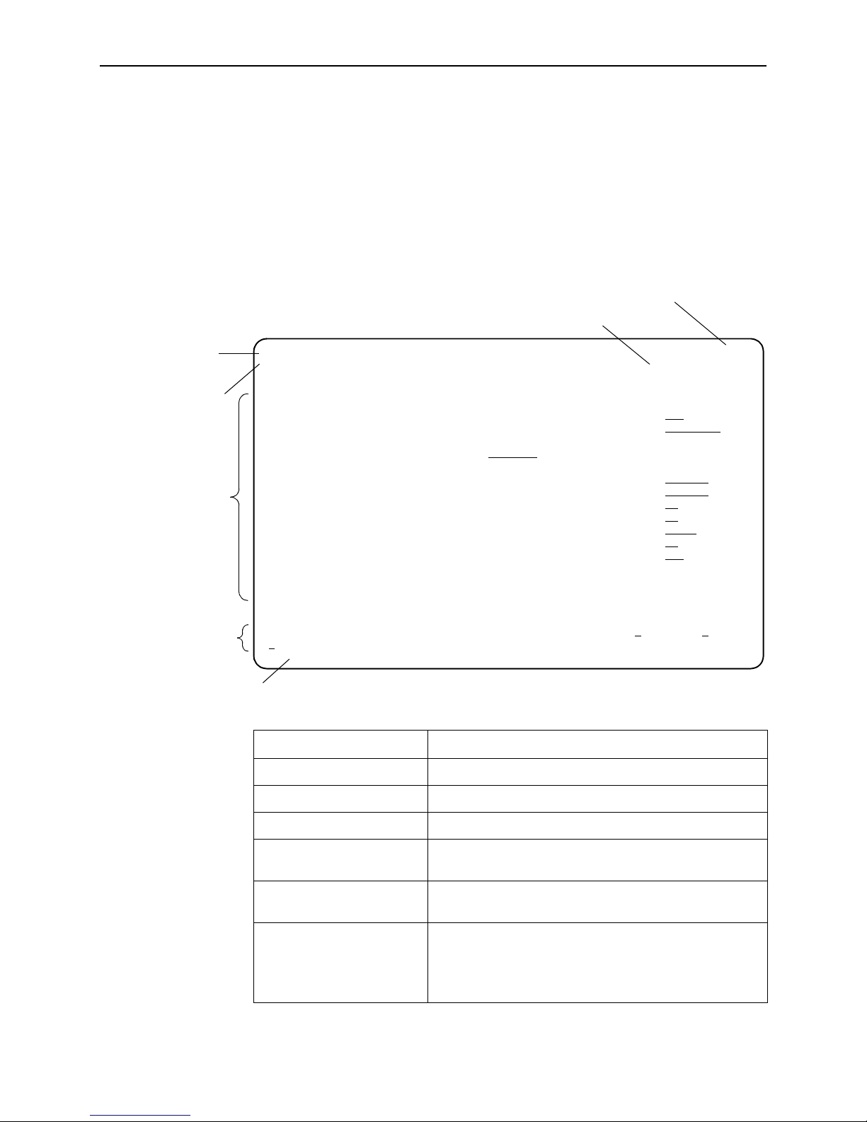
Below is a sample configuration screen.
1. User Interface and Basic Operation
Model Number
Date and Time
Menu Path
Device Name
Screen Area
Function Keys Area
Message Area
main /config/system/slv 9xxx-SLV
Device Name: Node A 08/23/2002 10:59
SERVICE LEVEL VERIFICATION SYSTEM OPTIONS
SLV Sample Interval (secs): 60
SLV Synchronization Role: Tributary
SLV Type: Standard
SLV Delivery Ratio: Disable
DLCI Down on SLV Timeout: Enable
SLV Timeout Error Event Threshold: 3
SLV Timeout Clearing Event Threshold: 1
SLV Round Trip Latency Error Threshold (ms): 10000
SLV Latency Clearing Event Threshold: 2
SLV Packet Size (bytes): 64
------------------------------------------------------------------------------Ctrl-a to access these functions, ESC for previous menu M
ave
S
ainMenu Exit
Screen Format Description
Menu Path Menu selections made to reach the current screen.
Device Name Customer-assigned identification of the iMarc unit.
9xxx-SLV iMarc unit’s model number (for example, 9126-IIRSLV).
Screen Area Selection, display, and input fields for monitoring and
Function Keys Area Specific functions that can be performed by pressing a
Message Area System-related information and valid settings for input
9000-A2-GB33-20 May 2003
maintaining the iMarc unit.
specified key, then pressing Enter.
fields are in the lower left corner.
System and Test Status messages are in the lower right
corner.
1-5
Page 16

1. User Interface and Basic Operation
Navigating the Screens
You can navigate the screens by:
Using keyboard keys.
Switching between the two screen work areas using function keys.
Keyboard Keys
Use the following keyboard keys to navigate within the screen area:
Press . . . To . . .
Ctrl-a Move cursor between the screen area and the
Esc Return to the previous screen.
screen function keys area.
Right Arrow (on same screen row), or
Tab (on any screen row)
Left Arrow (on same screen row), or
Ctrl-k
Backspace Move cursor one position to the left or to the last
Spacebar Select the next valid value for the field.
Delete (Del) Delete character that the cursor is on.
Up Arrow or Ctrl-u Move cursor up one field within a column on the
Down Arrow or Ctrl-d Move cursor down one field within a column on
Right Arrow or Ctrl-f Move cursor one character to the right if in edit
Left Arrow or Ctrl-b Move cursor one character to the left if in edit
Ctrl-l Redraw the screen display, clearing information
Enter (Return) Accept entry or, when pressed before entering
Move cursor to the next field.
Move cursor to the previous field.
character of the previous field.
same screen.
the same screen.
mode.
mode.
typed in but not yet entered.
data or after entering invalid data, display valid
options on the last row of the screen.
1-6 May 2003 9000-A2-GB33-20
Page 17
Function Keys
1. User Interface and Basic Operation
All function keys (located in the lower part of the screen; see the example in
Screen Work Areas on page 1-5) operate the same way throughout the screens.
They are not case-sensitive, so upper- or lowercase letters can be used
interchangeably.
These keys use the following conventions:
For the screen
Select . . .
M or m MainMenu Return to the Main Menu screen.
function . . . And press Enter to . . .
E or e E
N or n New Enter new data.
O or o Mo
L or l Del
S or s Save Save information.
R or r R
C or c C
U or u PgUp Display the previous page.
D or d PgD
xit Terminate the asynchronous terminal session.
dify Modify existing data.
ete Delete data.
efresh Update screen with current information.
lrStats Clear network performance statistics and refresh the
screen.
Variations include:
ClrSLV&DLCIStats for clearing SLV and DLCI
statistics.
ClrLinkStats for clearing frame relay link statistics.
ClrDBMStats for clearing DBM call statistics.
n Display the next page.
9000-A2-GB33-20 May 2003
1-7
Page 18

1. User Interface and Basic Operation
Selecting an Entry from a Menu
Procedure
To select an entry from a menu:
1. Tab or press the down arrow key to position the cursor on a menu selection, or
press the up arrow key to move the cursor to the bottom of the menu list.
Each menu selection is highlighted as you press the key to move the cursor
from position to position.
2. Press Enter. The selected menu or screen appears.
Procedure
To return to a previous screen, press the Escape (Esc) key until you reach the
desired screen.
Switching Between Screen Areas
Use Ctrl-a to switch between screen areas (see the example in Main Menu on
page 1-4).
Procedure
To switch to the function keys area:
1. Press Ctrl-a to switch from the screen area to the function keys area.
2. Select either the function’s designated (underlined) character or Tab to the
desired function key.
3. Press Enter. The function is performed.
To return to the screen area, press Ctrl-a again.
1-8 May 2003 9000-A2-GB33-20
Page 19

Selecting a Field
Entering Information
1. User Interface and Basic Operation
Once you reach the desired menu or screen, select a field to view or change, or
issue a command.
Press the Tab or right arrow key to move the cursor from one field to another. The
current setting or value appears to the right of the field.
You can enter information in one of three ways. Select the field, then:
Manually type in (enter) the field value or command.
Example:
Entering bjk as a user’s Login ID on the Administer Logins screen (from the
Control menu/branch).
Type in (enter) the first letter(s) of a field value or command, using the unit’s
character-matching feature.
Example:
When configuring a port’s physical characteristics with the Port (DTE) Initiated
Loopbacks configuration option/field selected ( possible settings include
Disable, Local, DTPLB, DCLB, and Both ), entering d or D displays the first
value starting with d – Disable. In this example, entering dt or DT would
display DTPLB as the selection.
Screen Contents
Switch to the function keys area and select or enter a designated function key.
Example:
To save a configuration option change, select S
ave. S or s is the designated
function key.
If a field is blank and the Message area displays valid selections, press the
spacebar; the first valid setting for the field appears. Continue pressing the
spacebar to scroll through other possible settings.
What appears on the screens depends on:
Current configuration – How your network is currently configured.
Security access level – The security level set by the system administrator for
each user.
Data selection criteria – What you entered in previous screens.
9000-A2-GB33-20 May 2003
1-9
Page 20
1. User Interface and Basic Operation
Navigating the Router’s CLI
Access the iMarc DSL Router’s Command Line Interface by pressing the Shift-r
function key from the Main Menu. There is no need to press Ctrl-a first to access
the function keys area of the screen.
Once the CLI is accessed, you can use keyboard keys to navigate within the
interface. Using the router’s CL I, you can display and edit router configuration
settings, view router status, and access router tests.
For details of all CL I commands and the conventions used when entering
commands, see the iMarc SLV Router Command Line Interface. That document
also contains a summary of abbreviated (minimal) command entries and their
default settings.
CLI Keyboard Keys
Use the following keyboard keys to navigate within the router’s CLI. Most terminal
emulation programs use these same keys.
Press . . . To . . .
Enter (Return) Accept the current command line input.
Ctrl-c
Ctrl-z Exit Configuration mode and returns to Standard mode. A prompt
Backspace Erase the character to the left of the cursor.
Delete Erase the character the cursor is on.
Down Arrow Recall command line history buffer with the most recent
Up Arrow Scroll to the last valid command for editing.
Right Arrow Move the cursor one position to the right.
Left Arrow Move the cursor one position to the left.
q
(or any key but
Spacebar or
Enter/Return)
Clear the current command line entry.
Abort a command line prompt without answering.
Exit a command in progress.
appears to save any unsaved changes.
command displaying first. Buffer contains ten lines of history.
Abort a Move display and return to the command line prompt.
1-10 May 2003 9000-A2-GB33-20
Page 21

Security and Logins
This chapter includes the following:
Limiting Access on page 2-2
Controlling Asynchronous Terminal Access on page 2-2
Limiting Dial-In Access via the Modem Port on page 2-4
Controlling ISDN Access on page 2-5
— ISDN Call Security
— Disabling ISDN Access
2
Controlling Telnet or FTP Access on page 2-6
— Limiting Telnet Access
— Limiting FTP Access
— Limiting Telnet or FTP Access Over the TS Access Management Link
Controlling SNMP Access on page 2-9
— Disabling SNMP Access
— Assigning SNMP Community Names and Access Levels
— Limiting SNMP Access Through IP Addresses
Creating a Login on page 2-12
Modifying a Login on page 2-13
Deleting a Login on page 2-13
Controlling Router CLI Access on page 2-14
9000-A2-GB33-20 May 2003 2-1
Page 22

2. Security and Logins
Limiting Access
The iMarc unit provides access security on the following interfaces:
Asynchronous terminal
Te ln et
FTP
SNMP
Up to two direct or Telnet sessions can be active at any given time; that is, you can
have two simultaneous Telnet sessions, or one Telnet session and one active
asynchronous terminal session, or two simultaneous asynchronous terminal
sessions.
Controlling Asynchronous Terminal Access
Direct asynchronous terminal access to the menu-driven user interface can be
limited by:
Requiring a login.
Assigning an access level to the port or interface.
An asynchronous terminal can be connected to the unit’s COM (communications)
port or its modem port.
2-2 May 2003 9000-A2-GB33-20
Page 23

2. Security and Logins
Procedure
To limit asynchronous terminal access to the menu-driven user interface:
1. Select the appropriate port options.
Main Menu → Configuration → Management and Communication →
Communication Port
Main Menu → Configuration → Management and Communication →
Modem Port
2. Set the following configuration options, as appropriate.
To . . . Set the configuration option . . .
Require a login Login Required to Enable.
NOTE: User ID and password combinations must
be defined. See Creating a Login on page 2-12.
Limit the effective access level
to Level-3 or Level-2
Port Access Level to Level-2 or Level-3.
NOTE: Regardless of a user’s login access level, a
user cannot operate at a level higher than the
access level specified for the port (e.g., if a user has
a Level-1 login and Level-2 port access has been
set, the Level-1 user can only operate as a Level-2
user).
If you are going to allow Level-1 users to configure
the unit, keep the access at Level-1.
NOTE:
See Resetting the Unit and Restoring Communication in Chapter 5,
Troubleshooting, should you be locked out inadvertently.
3. S
ave your changes.
If connecting an asynchronous terminal to the unit’s:
COM port – See the iMarc SLV Configuration Reference for more information
about the communication (COM) port.
Modem port – See Setting Up Call Directories for Trap Dial-Out and
Configuring the Modem Port in iMarc SLV Configuration Reference for
additional information.
9000-A2-GB33-20 May 2003
2-3
Page 24

2. Security and Logins
Limiting Dial-In Access via the Modem Port
The modem port is already configured for dial-in and asynchronous terminal
access; these are the default settings.
To limit dial-in access via the modem port, disable the Dial-In Access configuration
option.
Main Menu→ Configuration → Management and Communication →
Modem Port
See Configuring the Modem Port in the iMarc SLV Configuration Reference for
more information about modem port options.
2-4 May 2003 9000-A2-GB33-20
Page 25

Controlling ISDN Access
iMarc units with a DBM can limit access through the following methods:
ISDN Call Security
Disabling ISDN Access
ISDN Call Security
The iMarc unit uses the Caller Identification Method to screen calls and avoid
accidental or intentional disruption of network traffic. The answering DBM only
accepts calls with valid calling number identifiers or phone numbers.
When the ISDN DBM interface is enabled and Caller Identification Method is set to
Caller ID, the DBM takes advantage of ISDN services for network backup and
Calling Number Identification Service (CNIS) to provide backup security. ISDN
assures the integrity of calling party identifiers. The DBM uses the calling party
identifier to identify the calling unit and switches PVC connections as specified by
the user. No additional security is required.
2. Security and Logins
When the ISDN DBM interface is enabled and Caller Identification Method is set to
Proprietary, the DBM queries the originating unit for its Local Phone Number to
identify the calling unit. If the returned number is in one of the unit’s Inbound
Calling IDs, the call is accepted. If not, or if the queried unit does not respond
within five seconds, the unit drops the call.
See Caller Identification Method in the iMarc SLV Configuration Reference for
additional information.
Disabling ISDN Access
Procedure
To disable ISDN access:
See Configuring the ISDN DBM Interface in the iMarc SLV Configuration
Reference for more information about ISDN BRI or PRI DBM configuration
options.
1. Select the ISDN Physical options.
Main Menu → Configuration → ISDN→ Physical
2. Set Interface Status to Disable.
ave your change.
3. S
9000-A2-GB33-20 May 2003
2-5
Page 26

2. Security and Logins
Controlling Telnet or FTP Access
The iMarc unit provides several methods for limiting access via a Telnet or FTP
session. Telnet or FTP access can be on a standard management link or on a
service provider’s troubleshooting (TS) management link.
Limiting Telnet Access
Telnet access can be limited by:
Disabling Telnet access completely.
Requiring a login for Telnet sessions that are not on the TS Access
Management Link.
Assigning an access level for Telnet sessions.
Disabling TS Access Management Link access.
To limit Telnet access via a service provider’s troubleshooting management link,
see Limiting Telnet or FTP Access Over the TS Access Management Link on
page 2-8.
Procedure
To limit Telnet access when the session is not on the TS Access Management
Link:
1. Select the Telnet and FTP Session options.
Main Menu→ Configuration → Management and Communication →
Telnet and FTP Sessions
2. Set the following configuration options, as appropriate.
To . . . Set the configuration option . . .
Disable Telnet access Telnet Session to Disable.
Require a login Login Required to Enable.
NOTE: User ID and password combinations must
be defined. See Creating a Login on page 2-12.
Assign an access level Session Access Level to Level-2 or Level-3.
NOTE: Regardless of a user’s login access level, a
user cannot operate at a level higher than the
access level specified for the Telnet session (e.g., if
a user has a Level-1 login and Level-2 telnet access
has been set, the Level-1 user can only operate as
a Level-2 user).
If you are going to allow users to configure the unit,
keep the access at Level-1.
ave your changes.
3. S
2-6 May 2003 9000-A2-GB33-20
Page 27

Limiting FTP Access
2. Security and Logins
See Configuring Telnet and/or FTP Session Support in the iMarc SLV
Configuration Reference for more information about setting Telnet configuration
options.
FTP access can be limited by:
Disabling FTP access completely.
Requiring a user ID and password to login.
Limiting FTP bandwidth.
Procedure
To limit FTP access when the session is not on the TS Access Management Link:
1. Select the Telnet and FTP Session options.
Main Menu→ Configuration → Management and Communication →
Telnet and FTP Sessions
2. Set the following configuration options, as appropriate.
To . . . Set the configuration option . . .
Disable FTP FTP Session to Disable.
Require a login Login Required to Enable.
NOTE: User ID and password combinations must
be defined. See Creating a Login on page 2-12.
If you want to allow users to configure the unit or
perform file transfers, including downloads, keep
the access at Level-1.
Level-1 access is required to download software to
the unit, or to upload or download configuration
files. Level-3 is sufficient for NMS access for SLV
historical information.
Limit bandwidth for FTP FTP Max Transfer Rate to a rate less than the
network line speed, typically less than or equal to
the CIR.
This method is not recommended if SLV reports are
desired since FTP is required to generate the
reports.
3. S
ave your changes.
See Configuring Telnet and/or FTP Session Support in the iMarc SLV
Configuration Reference for more information about setting FTP configuration
options.
9000-A2-GB33-20 May 2003
2-7
Page 28

2. Security and Logins
Limiting Telnet or FTP Access Over the TS Access Management Link
Procedure
To limit Telnet or FTP access when the session is on the TS Access Management
Link:
1. Select the Telnet and FTP Session options.
Main Menu→ Configuration → Management and Communication →
Telnet and FTP Sessions
2. Disable Telnet Session and/or FTP Session, as appropriate.
3. Return to the Management and Communication menu, and select Node IP.
4. Set the following configuration options, as appropriate.
To . . . Set the configuration option . . .
Disable access via the TS
Access Management Link
Assign an access level to the
TS Access Management Link
ave your changes.
5. S
TS Access Management Link to None.
TS Access Management Link’s Access Level to
Level-2 or Level-3.
NOTE: Regardless of a user’s login access level, a
user cannot operate at a level higher than the
access level specified for the session (e.g., if a user
has a Level-1 login and Level-2 telnet access has
been set, the Level-1 user can only operate as a
Level-2 user).
If you are going to allow users to configure the unit,
keep the access at Level-1.
See Configuring Telnet and/or FTP Session Support or Configuring Node IP
Information in the iMarc SLV Configuration Reference for more information about
these configuration options.
2-8 May 2003 9000-A2-GB33-20
Page 29

Controlling SNMP Access
The iMarc unit supports SNMP Version 1, which provides limited security through
the use of community names. There are three methods for limiting SNMP access:
Disabling SNMP access.
Assigning SNMP community names and the access type.
Assigning IP addresses of those NMSs that can access the unit.
Disabling SNMP Access
When the SNMP access is disabled, the iMarc unit will not respond to SNMP
messages.
Procedure
To disable SNMP access:
1. Select the General SNMP Management options.
2. Security and Logins
Main Menu → Configuration → Management and Communication →
General SNMP Management
2. Disable the SNMP Management option.
3. S
ave your change.
See Configuring General SNMP Management in the iMarc SLV Configuration
Reference for more information about General SNMP Management configuration
options.
9000-A2-GB33-20 May 2003
2-9
Page 30
2. Security and Logins
Assigning SNMP Community Names and Access Levels
The iMarc unit supports the SNMP protocol and can be managed by an SNMP
manager. SNMP manager access can be limited by:
Assigning the SNMP community names that are allowed to access the iMarc
unit’s Management Information Base (MIB).
Specifying the type of access allowed for each SNMP community name.
Whenever an SNMP manager attempts to access an object in the MIB, the
community name must be supplied.
Procedure
To assign SNMP community names and access types:
1. Select the General SNMP Management options.
Main Menu → Configuration → Management and Communication →
General SNMP Management
2. Set the following configuration options, as appropriate.
To . . . Set the configuration option . . .
Assign SNMP community
names
Assign the type of access
allowed for the SNMP
community names
3. S
ave your changes.
Community Name 1 and Community Name 2 to a
community name text, up to 255 characters in length.
Name 1 Access and Name 2 Access to Read or
Read/Write.
See Configuring General SNMP Management in the iMarc SLV Configuration
Reference for more information about General SNMP Management configuration
options.
2-10 May 2003 9000-A2-GB33-20
Page 31

Limiting SNMP Access Through IP Addresses
An additional level of security is provided by:
Limiting the IP addresses of NMSs that can access the iMarc unit.
Performing validation checks on the IP address of SNMP management
systems attempting to access the iMarc unit.
Specifying the access allowed for the authorized NMS when IP address
validation is performed.
The SNMP NMS Security Options screen provides the configuration options that
determine whether security checking is performed on the IP address of SNMP
management systems attempting to communicate with the unit.
Make sure that SNMP Management is set to Enable.
Menu selection sequence:
Main Menu → Configuration → Management and Communication →
General SNMP Management → SNMP Management: Enable
See Configuring General SNMP Management in the iMarc SLV Configuration
Reference for more information about SNMP management configuration options.
2. Security and Logins
Procedure
To limit SNMP access through IP addresses:
1. Select the SNMP NMS Security options:
Main Menu→ Configuration→ Management and Communication→ SNMP
NMS Security
2. Select and set the following configuration options, as appropriate.
To . . . Set the configuration option . . .
Enable IP address checking NMS IP Validation to Enable.
Specify the number (between 1 and 10) of
SNMP management systems that are
authorized to send SNMP messages to the
iMarc unit
Specify the IP address(es) that identifies the
SNMP manager(s) authorized to send
SNMP messages to the unit
Specify the access allowed for an authorized
NMS when IP address validates is
performed
Number of Managers to the desired
number.
NMS n IP Address to the appropriate
IP address.
Access Level to Read or Read/Write.
ave your changes.
3. S
See Configuring SNMP NMS Security in the iMarc SLV Configuration Reference
for more information about SNMP NMS Security configuration options.
9000-A2-GB33-20 May 2003
2-11
Page 32

2. Security and Logins
Creating a Login
A login is required if security is enabled. Security is enabled by the configuration
options Login Required for the communication port, modem port, and Telnet Login
Required or FTP Login Required for a Telnet or FTP Session.
Up to six login ID/password combinations can be created using ASCII text, and
each login must have a specified access level. Logins must be unique and they are
case-sensitive.
Procedure
To create a login record:
1. Select Administer Logins.
Main Menu → Control→ Administer Logins
2. Select N
ew, and set the following configuration options, as appropriate.
In the field . . . Enter the . . .
Login ID ID of 1 to 10 characters.
Password Password from 1 to 10 characters.
Re-enter password Password again to verify that you entered the correct
password into the device.
Access Level Access level: 1, 2, or 3.
Level-1 – User can add, change, and display
configuration options, save, and perform device
testing.
Level-2 – User can monitor and perform
diagnostics, display status and configuration option
information.
Level-3 – User can only monitor and display status
and configuration screens.
CAUTION: Make sure at least one login is set up for
Level-1 access or you may be inadvertently locked out.
NOTE:
ave your changes.
3. S
When Save is complete, the cursor is repositioned at the Login ID field, ready
for another entry.
See Configuring SNMP NMS Security in the iMarc SLV Configuration Reference
for more information about security configuration options.
2-12 May 2003 9000-A2-GB33-20
See Resetting the Unit and Restoring Communication in Chapter 5,
Troubleshooting, should you be locked out inadvertently.
Page 33

Modifying a Login
Logins are modified by deleting the incorrect login and creating a new one.
Deleting a Login
Procedure
To delete a login record:
1. Select Administer Logins.
2. Security and Logins
Main Menu → Control→ Administer Logins
2. Page through login pages/records using the PgU
the login to be deleted is displayed.
3. Select De l
ave your deletion.
4. S
When the deletion is complete, the number of login pages /records reflects
one less record, and the record before the deleted record reappears.
Example:
Page 2 of 4 is changed to Page 2 of 3.
ete.
p or PgDn function keys until
9000-A2-GB33-20 May 2003
2-13
Page 34

2. Security and Logins
Controlling Router CLI Access
iMarc SLV Routers can be managed from an NMS using SNMP, or from the
router’s command line interface (CLI). There are two methods to access the
command line interface:
Local access at the router through the COM port, or
Access via a Telnet session.
Telnet access defaults to Administrator level. If the current login is at the
Operator level, only Operator level access is available for the session. Telnet
access is always enabled.
The router accepts one CLI login session at a time and is configured at the factory
without a default login ID and password. To provide login security to the system,
configure a login ID and password.
When a local console connection is first established, a login prompt appears. If the
Device Name field has been configured via the Control menu
(Control Menu → System Information), the login prompt displays the device name.
For example, a device name of Largo is shown as:
Largo>
See Creating a Login on page 2-12 for security information for each Login ID.
Access Levels (Command Modes)
There is one login ID and several levels of privileges for the router’s CLI. Your user
account can be configured with one user name and different passwords for:
Operator. The Operator has read-only access to display device information
with no modification permission and limited access to diagnostic functions.
With a device name of Largo, the prompt appears as Largo>.
Administrator. The Administrator has several levels of access to the router’s
CLI. The # sign in the following prompts indicates Administrator access level.
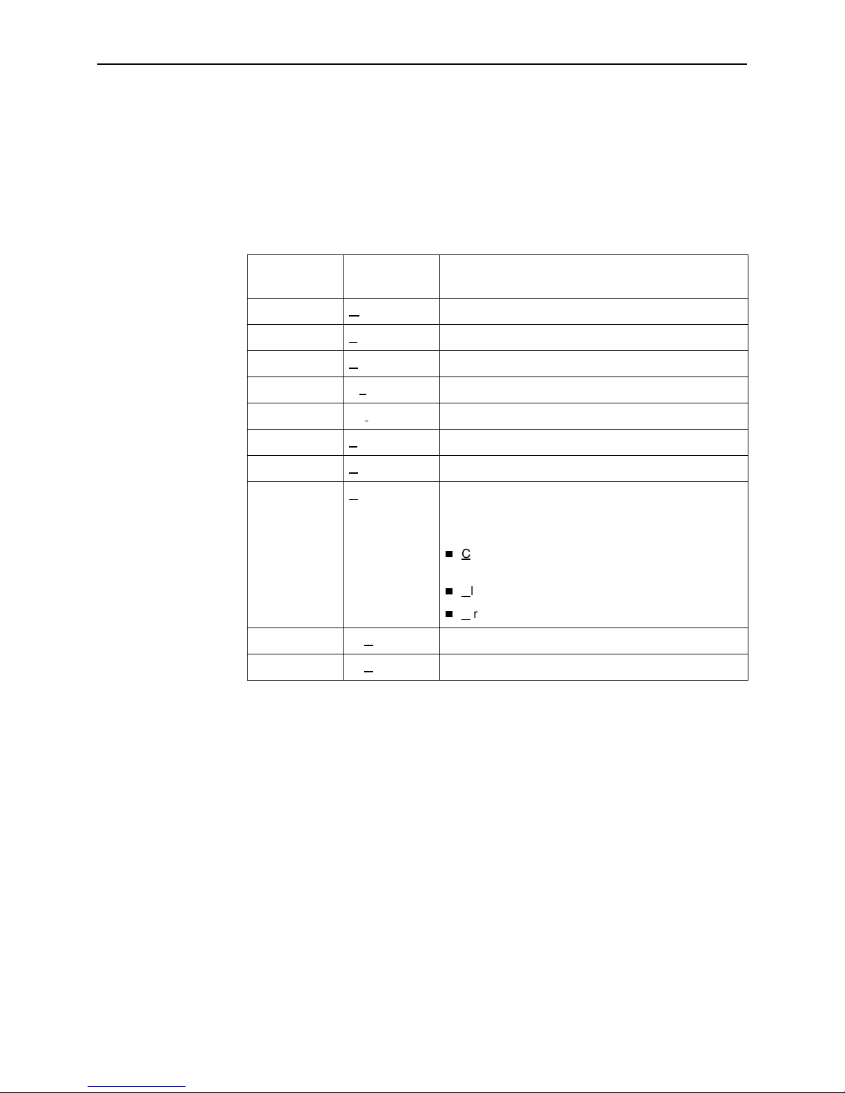
Display Prompt with Device Name of Largo Administrator Access Levels
Largo #> Standard (same as Operator)
Largo(config) # Configuration
Largo(config-if) # Configuration Interface
Largo(config-subif) # Configuration Sub-Interface
Largo(config-dhcp) # Configuration DHCP Pool
Refer to the iMarc SLV Router Command Line Interface for access level details for
each command line entry.
2-14 May 2003 9000-A2-GB33-20
Page 35

Changing Access Levels
The Operator and Administrator have the same Login ID with different passwords
for their access level. To determine the level of access for a session, refer to
Access Levels (Command Modes) on page 2-14.
After accessing the router’s CLI:
You can access the Administrator access level by entering:
The router’s defaults to no password required. To require a password to
You can end the current Administrator access level by entering:
2. Security and Logins
enable
access the Administrator access level, enter:
enable password password
Once saved, the router responds with a prompt to enter a password for
Administrator access. This command is in effect until no enable password
[ password ] is entered and saved.
exit
This command results in ending the current Administrator access level
session. Exit may need to be entered several times to reach Operator level
and/or end the session.
You can end the Administrator access level by entering:
end
This command results in ending the Administrator access level session and
returning immediately to Operator level.
For further details, refer to the iMarc SLV Configuration Reference and iMarc SLV
Router Command Line Interface.
9000-A2-GB33-20 May 2003
2-15
Page 36

2. Security and Logins
2-16 May 2003 9000-A2-GB33-20
Page 37

Status and Statistics
This chapter describes the ways you can determine device and network status
and obtain statistics.
Displaying System Information on page 3-2
Viewing LEDs and Control Leads on page 3-4
— LED Descriptions
— Power Module LEDs (Models 9520, 9520-ILM, 9820-45M)
— Display LEDs and Control Leads Screen Descriptions
Device Messages on page 3-24
3
Status Information on page 3-30
— System and Test Status Messages
— Network LMI-Reported DLCIs Status
— IP Path Connection Status
— PVC Connection Status
— Time Slot Assignment Status
— DBM Interface Status
IP Routing Table on page 3-60
Performance Statistics on page 3-62
— Clearing Performance Statistics
— Service Level Verification Performance Statistics
— DLCI Performance Statistics
— Frame Relay Performance Statistics
— PPP Performance Statistics
— ATM Performance Statistics (9783, 9788)
— VCC Performance Statistics (9783, 9788)
— ESF Line Performance Statistics (9123, 9126, 9128)
9000-A2-GB33-20 May 2003 3-1
Page 38

3. Status and Statistics
— DDS Line Performance Statistics (9623, 9626)
— T3 Network Line Performance Statistics (9520, 9520-ILM)
— SHDSL Line Performance Statistics (9788)
— DBM Call Performance Statistics
— Ethernet Performance Statistics
Trap Event Log on page 3-91
Displaying System Information
Use the Identity screen to view identification information about the iMarc unit. This
information is useful if you are purchasing additional or replacement units and/or
making firmware upgrades.
Main Menu→ Status→ Identity
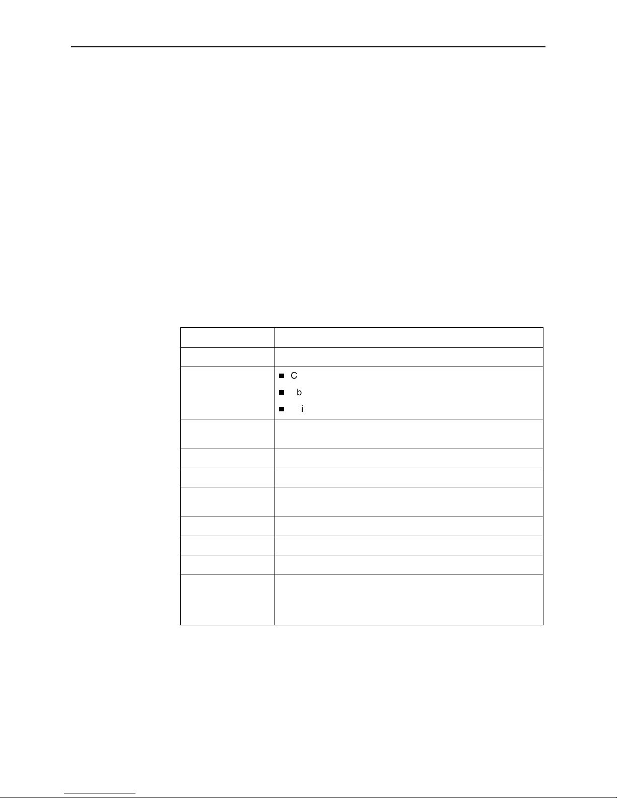
View this field . . . To find the . . .
System Name Domain name for this SNMP-managed node (up to 255
ASCII characters).
System Contact Contact person for this SNMP-managed node.
System Location Physical location for this SNMP-managed node.
NAM
NAM Type Type of unit installed, referred to as a network access
module, or NAM (i.e., T1 FR NAM). This card type is
supported by the SNMP SysDescr Object.
Hardware Revision Unit’s hardware version. Format nnnn-nnx consists of a
4-digit number, followed by two digits and one alphabetic
character.
Current Software Revision Software version currently being used by the unit. Format
nn.nn.nn consists of a 6-digit number that represents the
major and minor revision levels.
Alternate Software Revision Software version that has been downloaded into the unit,
but has not yet been implemented. Format is the same as
for the Current Software Revision.
In Progress indicates that the flash memory is
currently being downloaded.
Invalid indicates that no download has occurred or
the download was not successful
Serial Number Unit’s 7-character serial number.
Ethernet MAC Address Media Access Control (MAC) address assigned to the
3-2 May 2003 9000-A2-GB33-20
Ethernet port during manufacturing.
Page 39

3. Status and Statistics
View this field . . . To find the . . .
ISDN DBM
Card Type The type of dial backup module installed, ISDN-BRI or
ISDN-PRI, if applicable.
If an unsupported DBM is installed, Unsupport
displays.
If the DBM has failed, Failed displays.
Software Revision Software version currently being used by the iMarc unit’s
DBM. Format nn.nn.nn consists of a 6-digit number that
represents the major and minor revision levels.
For an ISDN-PRI DBM, None displays because the DBM
does not have loaded software; it runs from the NAM’s
software.
Hardware Revision iMarc DBM’s hardware version. Format nnnn-nnx consists
of a 4-digit number, followed by 2 digits and 1 alphabetic
character.
9000-A2-GB33-20 May 2003
3-3
Page 40

3. Status and Statistics
Viewing LEDs and Control Leads
iMarc SLV faceplates include LEDs (light-emitting diodes) that provide status on
the unit and its interfaces.
The Display LEDs and Control Leads feature allows you to monitor a remote unit;
it is useful when troubleshooting control lead problems. The Display LEDs and
Control Leads screen shows the status of the unit and its interfaces.
To access the Display LEDs and Control Leads screen:
Main Menu → Status → Display LEDs and Control Leads
The following illustrations compare front panel LEDs and the Display LEDs and
Control Leads screens for each model type.
Model 9123
9123-C
FLEX
SLV
ALM
OK
TEST
FR
OOF
SIG
NetworkSystem
ALM
Model 9123 Display LEDs and Control Leads Screen
OK
Por t
03-17386
3-4 May 2003 9000-A2-GB33-20
Page 41

Model 9126-A2-201
9126
SLV
ALM
OK
SIG
TST
NETWORK DSX PORT
Model 9126-A2-202
9126
SIG
BKP
ALM
OK
SLV
TST
NETWORK DSX PORT
Model 9126 Display LEDs and Control Leads Screen
OOF
OOF
3. Status and Statistics
OOF
OOF
ALM
ALM
OK
03-17409
OK
03-17410
ALM
ALM
SIG
SIG
9000-A2-GB33-20 May 2003
3-5
Page 42

3. Status and Statistics
Model 9128
9128
FR
BKP
ALM
OK
SLV
SLV
TST
Model 9128 Display LEDs and Control Leads Screen
SIG
ALM
OOF
SIG
NETWORK DSX/PRI PORT
OOF
ALM
03-17399
OK
3-6 May 2003 9000-A2-GB33-20
Page 43

Model 9520
3. Status and Statistics
9520
SYSTEM
OK
ALM
TST
FAN
PWR
TD
RD
LMI
OOF
LOS
PORT 1
TD
RD
DSR
DTR
PORT 2NETWORK
TD
RD
DSR
DTR
AIS
YEL
iMarc
T
M
SLV
S
Y
S
T
E
M
O
K
9520
N
E
T
A
W
L
O
M
R
K
T
T
D
S
T
P
F
R
O
A
D
R
N
T
1
L
P
T
M
D
W
I
R
O
R
O
D
F
L
O
S
A
O
I
O
S
F
L
Y
O
E
L
S
A
I
S
Y
E
L
Model 9520 Display LEDs and Control Leads Screen
03-17387
9000-A2-GB33-20 May 2003
3-7
Page 44

3. Status and Statistics
Model 9520-ILM
9520-ILM
SYSTEM
OK
ALM
TST
FAN
PWR
TD
RD
LMI
OOF
LOS
AIS
YEL
PORT 1NETWORK
TD
RD
OOF
LOS
AIS
YEL
iMarc
®
SLV
S
Y
S
T
E
M
O
9520-ILM
K
N
E
T
A
W
L
O
M
R
K
T
T
D
S
T
P
F
R
O
A
D
R
N
T
1
L
P
T
M
D
W
I
R
O
R
O
D
F
L
O
S
O
A
O
I
S
F
L
Y
O
E
L
S
A
I
S
Y
E
L
Model 9520-ILM Display LEDs and Control Leads Screen
03-17391
3-8 May 2003 9000-A2-GB33-20
Page 45

Model 9623
3. Status and Statistics
9623
FrameSaverTMSLV
FLEX
ALM
OK
TESTFRDM
OOS
OOF/NS
NetworkSystem
Model 9626
9626
DM
BKP
ALM
OK
SLV
SLV
TST
NETWORK
Model 9626 Display LEDs and Control Leads Screen
OOS
OOF/NS
Por t
OK
03-17384
1-OK
PORT
03-17385
2-OK
9000-A2-GB33-20 May 2003
3-9
Page 46

3. Status and Statistics
Model 9720 CSU/DSU and Router
R
OK
ALM
9720
TEST
FR
DSL
DSL
IDSL
NetworkSystem
Model 9720 Display LEDs and Control Leads Screen
OK
Por t
03-17411
3-10 May 2003 9000-A2-GB33-20
Page 47

Model 9783
3. Status and Statistics
R
FrameSaverTMSLV
DSL
SDSL
OK
ALM
9783-C
TEST
ATM
DSL
NetworkSystem
Model 9788
R
FrameSaverTMSLV
DSL
SHDSL
ALM
OK
9788 CSU/DSU
ATM
TEST
NetworkSystem
DSL
Model 9783 Display LEDs and Control Leads Screen
OK
Por t
03-17407
OK
Por t
03-17408
9000-A2-GB33-20 May 2003
3-11
Page 48

3. Status and Statistics
Model 9783 Router
SDSL
DSL
R
SLV
9783
ROUTER
ALM
OK
TEST
ATM
DSL
NetworkSystem
Model 9788 Router
R
9788
ROUTER
ALM
OK
TEST
ATM
DSL
DSL
SHDSL
NetworkSystem
Model 9783 Router Display LEDs and Control Leads Screen
OK
Por t
03-17405
OK
Por t
03-17406
3-12 May 2003 9000-A2-GB33-20
Page 49

Model 9820-2M and 9820-8M
9820-2M
ALM
OK
SLV
SLV
TST
NETWORK PORT
Model 9820-2M Display LEDs and Control Leads Screen
3. Status and Statistics
OK
OK
03-17383
9000-A2-GB33-20 May 2003
3-13
Page 50

3. Status and Statistics
Model 9820-45M
9820-45M
SYSTEM
OK
ALM
TST
FAN
LMI
TD
RD
DTR
DSR
PORT 1NETWORK
TD
RD
DSR
DTR
PWR
iMarc
T
M
SLV
S
Y
S
T
E
M
O
9820-45M
K
A
L
M
N
L
T
E
M
S
T
T
I
W
O
F
R
A
K
N
P
T
D
W
R
P
R
O
D
R
T
1
D
T
D
T
R
D
R
S
D
R
D
T
R
D
S
R
03-17388
Model 9820-45M Display LEDs and Control Leads Screen
R
efresh the screen to view control lead transitions. LED and control lead
descriptions are in the sections that follow.
3-14 May 2003 9000-A2-GB33-20
Page 51

LED Descriptions
3. Status and Statistics
Table 3-1, Front Panel LEDs, decribes the LEDs found on the faceplates of iMarc
devices.
Table 3-1. Front Panel LEDs (1 of 4)
Label Indication Color What It Means
General and System
OK Power and
Operational
Status
ALM Operational
Alarm (Fail)
TST Test Mode Yellow ON – Loopback or test pattern is in progress,
Models 9126, 9128, 9626 with ISDN Backup:
BKP Backup Yellow ON – iMarc unit is in Backup mode; that is, the
Green ON – iMarc unit has power and it is
operational.
OFF – iMarc unit is in a power-on self-test, or
there is a failure.
Red ON – iMarc unit has just been reset, or an error
or fault has been detected.
Alarms appear on the System and Test Status
screen. See Table 3-6, Health and Status
Messages, for additional information.
initiated locally, remotely, or from the network.
OFF – No tests are active.
backup link has been established, and backup
is in progress through the specified Alternate
Destination Link.
OFF – iMarc unit is not in Backup mode.
Blinking ON and OFF – Alternate Destination
Link is being established, but no data has been
passed.
Models 9520, 9520-ILM, 9820-45M:
FAN Fan Status Yellow ON – One or more of the four system fans has
PWR Power Supply
Status
9000-A2-GB33-20 May 2003
Yellow ON – One of the two installed power modules
failed.
OFF – All fans are operational.
has failed. See Power Module LEDs (Models
9520, 9520-ILM, 9820-45M) on page 3-19.
OFF – Both power modules are operational or
a redundant power supply is not installed.
3-15
Page 52

3. Status and Statistics
Table 3-1. Front Panel LEDs (2 of 4)
Label Indication Color What It Means
Network
Models 9123, 9128, 9623, 9720:
Link
or
FR
Models 9783, 9788:
ATM ATM Status Multi-
Models 9520, 9520-ILM, 9820-45M:
TD Transmit Data Green ON – At least one non-idle cell was transmitted
RD Receive Data Green ON – At least one non-idle cell was received
LMI LMI Status Green ON – LMI is operating successfully on the
Mode and Link
Status
Multicolored
colored
Yellow – Depending on service mode, PPP or
LMI is down.
Green – Depending on service mode, PPP or
LMI is up.
OFF – Leased line mode is active (9123 and
9623), or the link is down.
Yellow – ATM is down.
Green – ATM is up.
to the network during the sampling period.
OFF – No non-idle cell was transmitted to the
network during the sampling period.
from the network during the sampling period.
OFF – No non-idle cell was received from the
network during the sampling period.
frame relay link.
OFF – LMI is not operating successfully.
Models 9520, 9520-ILM:
OOF Out Of Frame Green ON – At least one OOF error was detected on
the network during the sampling period.
OFF – No OOF error was detected on the
network during the sampling period.
LOS Loss Of Signal Green ON – An LOS error was detected on the
network during the sampling period.
OFF – No LOS error was detected on the
network during the sampling period.
AIS Alarm Indication
Signal
YEL Yellow Alarm Green ON – A Yellow Alarm condition existed during
Green ON – An AIS was received during the sampling
period.
OFF – No AIS was received during the
sampling period.
the sampling period (meaning that the far-end
equipment reported an OOF or LOF error).
OFF – No Yellow Alarm condition was detected
during the sampling period.
3-16 May 2003 9000-A2-GB33-20
Page 53

Table 3-1. Front Panel LEDs (3 of 4)
Label Indication Color What It Means
Network, continued
Model 9820-45M:
3. Status and Statistics
DTR Data Terminal
Ready
DSR Data Set Ready Green ON – The DSR lead is asserted.
Network, DSX-1, or ISDN PRI DBM
Models 9123, 9126, 9128:
SIG T1 Signal Green ON – A recoverable signal is present on the
OOF Out of Frame Yellow ON – At least one OOF was detected during
ALM Alarm Yellow ON – An alarm condition is present on the
Port
Green ON – The DTR lead is asserted.
OFF – The DTR lead is not asserted.
OFF – The DSR lead is not asserted.
Network/DSX/PRI interface.
OFF – The signal cannot be recovered from
the Network/DSX/PRI interface. An LOS
condition exists.
the sampling period.
OFF – No OOFs were detected during the
sampling period.
network/DSX/PRI interface.
OFF – No alarm condition is present on the
Network/DSX/PRI interface.
OK Operational
Status
Models 9520, 9520-ILM, 9820-45M:
TD Transmit Data Green ON – At least one transmit frame was received
RD Receive Data Green ON – At least receive frame was transmitted to
Green ON – The interchange circuits for the port are
in the correct state to transmit and receive
data. For 9128 units (which have two data
ports but one related LED), at least one of the
ports is enabled and active.
OFF – The port is idle. Occurs if the port is
disabled, or if the port is configured to monitor
DTR and/or RTS and the lead(s) is not
asserted. For 9128 units, both ports are
enabled and at least one is inactive.
from the DTE during the sampling period.
OFF – No transmit frame was received from
the DTE during the sampling period.
the DTE during the sampling period.
OFF – No receive frame was transmitted to the
DTE during the sampling period.
9000-A2-GB33-20 May 2003
3-17
Page 54

3. Status and Statistics
Table 3-1. Front Panel LEDs (4 of 4)
Label Indication Color What It Means
Port, continued
Models 9520, 9820-45M:
DTR Data Terminal
Ready
DSR Data Set Ready Green ON – The DSR lead is asserted.
Model 9520-ILM:
OOF Out Of Frame Green ON – At least one OOF error was detected on
LOS Loss Of Signal Green ON – An LOS error was detected on the
AIS Alarm Indication
Signal
YEL Yellow Alarm Green ON – A Yellow Alarm condition existed during
Green ON – The DTR lead is asserted.
OFF – The DTR lead is not asserted.
OFF – The DSR lead is not asserted.
the network during the sampling period.
OFF – No OOF error was detected on the
network during the sampling period.
network during the sampling period.
OFF – No LOS error was detected on the
network during the sampling period.
Green ON – An AIS was received during the sampling
period.
OFF – No AIS was received during the
sampling period.
the sampling period (meaning that the far-end
equipment reported an OOF or LOF error).
OFF – No Yellow Alarm condition was detected
during the sampling period.
3-18 May 2003 9000-A2-GB33-20
Page 55

Power Module LEDs (Models 9520, 9520-ILM, 9820-45M)
Each power module has a green LED which remains lit while power is applied and
the power module is functioning.
When the yellow front panel System PWR LED is lit, one of the power modules
has failed. The failed power module can be identified from the back of the DSU by
its unlit LED.
Table 3-2. Power Module Troubleshooting
What to Do
Configuration Symptom
(in order, if problem persists)
3. Status and Statistics
One Power
Module
Two Power
Modules
No front panel
LEDs are lit.
No front panel
LEDs are lit.
The front panel
System PWR LED
is lit.
1. Verify that the receptacle in use provides
120 Vac.
2. Verify that the power module switch is in the On
position.
3. Replace the power module. See Replacing a
Power Module in Chapter 4, Operation and
Maintenance.
4. Call your service representative.
1. Verify that the receptacles in use provide
120 Vac.
2. Verify that the power module switches are in
the On position.
3. Replace the power modules. See Replacing a
Power Module in Chapter 4, Operation and
Maintenance.
4. Call your service representative.
1. Check the power module LEDs from the back
of the unit and replace the failed power module
(the one whose LED is off). See Replacing a
Power Module in Chapter 4, Operation and
Maintenance.
2. Call your service representative.
9000-A2-GB33-20 May 2003
3-19
Page 56

3. Status and Statistics
Display LEDs and Control Leads Screen Descriptions
Table 3-3, Display LEDs and Control Leads Screen Labels, explains the notations
on the Display LEDs and Control Leads screens. An ON condition is denoted by
inverse text and an OFF condition by normal text. See the screen examples in
Viewing LEDs and Control Leads on page 3-4.
Table 3-3. Display LEDs and Control Leads Screen Labels (1 of 4)
Label Indication What It Means
General
OK Power and
Operational
Status
Alarm Operational
Alarm (Fail )
Test Test Mode ON – Loopback or test pattern is in progress, initiated
Models 9126, 9128, 9626 with ISDN Backup:
Backup Backup ON – iMarc unit is in Backup mode; that is, the backup
Models 9520, 9520-ILM, 9820-45M:
Fan Fail Fan Status ON – One or more of the four system fans has failed.
ON – iMarc unit has power and it is operational.
OFF – iMarc unit is in a power-on self-test, or there is a
failure.
ON – iMarc unit has just been reset, or an error or fault
has been detected.
Alarms appear on the System and Test Status screen.
See Table 3-6, Health and Status Messages, for
additional information.
locally, remotely, or from the network.
OFF – No tests are active.
link has been established, and backup is in progress
through the specified Alternate Destination Link.
OFF – iMarc unit is not in Backup mode.
Blinking ON and OFF – Alternate Destination Link is
being established, but no data has been passed.
OFF – All fans are operational.
Pwr Fail Power Supply
All models except 9783, 9788:
FR Mode Service Mode ON – The unit is in frame relay mode.
PPP Mode Service Mode ON – The unit is in PPP mode.
Models 9123, 9623:
LL Mode Service Mode ON – The unit is in leased line mode.
3-20 May 2003 9000-A2-GB33-20
Status
ON – One of the two installed power modules has failed.
See Power Module LEDs (Models 9520, 9520-ILM,
9820-45M) on page 3-19.
OFF – Both power modules are operational or a
redundant power supply is not installed.
Page 57

3. Status and Statistics
Table 3-3. Display LEDs and Control Leads Screen Labels (2 of 4)
Label Indication What It Means
General, continued
Models 9783 and 9788 CSU/DSUs and Routers:
ATM Mode ATM Status ON – ATM is up.
Network1
Model 9720:
OK Network Status ON – The IDSL network interface is operational.
OFF – The IDSL network interface is not operational.
Models 9520, 9520-ILM, 9820-45M:
TD Transmit Data ON – At least one non-idle cell was transmitted to the
network during the sampling period.
OFF – No non-idle cell was transmitted to the network
during the sampling period.
RD Receive Data ON – At least one non-idle cell was received from the
network during the sampling period.
OFF – No non-idle cell was received from the network
during the sampling period.
Models 9520, 9520-ILM, 9720, 9820-45M:
LMI OK LMI Status ON – LMI is operating successfully on the frame relay
link.
OFF – LMI is not operating successfully.
Models 9520, 9520-ILM:
OOF Out Of Frame ON – At least one OOF error was detected on the
network during the sampling period.
OFF – No OOF error was detected on the network
during the sampling period.
LOS Loss Of Signal ON – An LOS error was detected on the network during
the sampling period.
OFF – No LOS error was detected on the network
during the sampling period.
AIS Alarm Indication
Signal
YEL Yellow Alarm ON – A Yellow Alarm condition existed during the
ON – An AIS was received during the sampling period.
OFF – No AIS was received during the sampling period.
sampling period (meaning that the far-end equipment
reported an OOF or LOF error).
OFF – No Yellow Alarm condition was detected during
the sampling period.
9000-A2-GB33-20 May 2003
3-21
Page 58

3. Status and Statistics
Table 3-3. Display LEDs and Control Leads Screen Labels (3 of 4)
Label Indication What It Means
Network1, continued
Models 9783 and 9788 CSU/DSUs and Routers:
Data Mode Data Mode
Active
LOS Loss Of Signal ON – An LOS condition has been detected on the
Training Training in
Progress
LCD Loss of Cell
Delineation
Model 9820-45M:
DTR Data Terminal
Ready
DSR Data Set Ready ON – The DSR lead is asserted.
Models 9123, 9126, 9128:
SIG T1 Signal ON – A recoverable signal is present on the
ON – The unit has trained up and is operating in normal
data mode. The front panel DSL LED is on.
OFF – The unit has not trained up.
network. The front panel ALM LED is on.
OFF – No LOS condition is detected.
ON – The unit is training and the DSL LED is flashing.
OFF – The unit is not training.
ON – An LCD alarm condition has been detected. On
the 9783, the front panel ATM LED is yellow.
OFF – No LCD condition is detected.
ON – The DTR lead is asserted.
OFF – The DTR lead is not asserted.
OFF – The DSR lead is not asserted.
Network/DSX/PRI interface.
OFF – The signal cannot be recovered from the
Network/DSX/PRI interface. An LOS condition exists.
OOF Out of Frame ON – At least one OOF was detected during the
ALM Alarm ON – An alarm condition is present on the
Port-n
Models 9123, 9126, 9128, 9623, 9626, 9720, 9783, 9788:
OK Operational
3-22 May 2003 9000-A2-GB33-20
Status
sampling period.
OFF – No OOFs were detected during the sampling
period.
network/DSX/PRI interface.
OFF – No alarm condition is present on the
Network/DSX/PRI interface.
ON – The interchange circuits for the port are in the
correct state to transmit and receive data.
OFF – The port is idle. Occurs if the port is disabled, or
if the port is configured to monitor DTR and/or RTS and
the lead(s) is not asserted.
Page 59

3. Status and Statistics
Table 3-3. Display LEDs and Control Leads Screen Labels (4 of 4)
Label Indication What It Means
Port, continued
Models 9520, 9520-ILM, 9820-45M:
TD Transmit Data ON – At least one transmit frame was received from the
DTE during the sampling period.
OFF – No transmit frame was received from the DTE
during the sampling period.
RD Receive Data ON – At least receive frame was transmitted to the DTE
during the sampling period.
OFF – No receive frame was transmitted to the DTE
during the sampling period.
Models 9520, 9820-45M:
DTR Data Terminal
Ready
DSR Data Set Ready ON – The DSR lead is asserted.
Model 9520-ILM:
OOF Out Of Frame ON – At least one OOF error was detected on the
LOS Loss Of Signal ON – An LOS error was detected on the network during
AIS Alarm Indication
Signal
YEL Yellow Alarm ON – A Yellow Alarm condition existed during the
ON – The DTR lead is asserted.
OFF – The DTR lead is not asserted.
OFF – The DSR lead is not asserted.
network during the sampling period.
OFF – No OOF error was detected on the network
during the sampling period.
the sampling period.
OFF – No LOS error was detected on the network
during the sampling period.
ON – An AIS was received during the sampling period.
OFF – No AIS was received during the sampling period.
sampling period (meaning that the far-end equipment
reported an OOF or LOF error).
OFF – No Yellow Alarm condition was detected during
the sampling period.
Ethernet
Models 9126, 9783, and 9788 Routers:
OK Operational
9000-A2-GB33-20 May 2003
Status
ON – The Ethernet interface is operational.
OFF – The Ethermet interface is not operational.
3-23
Page 60

3. Status and Statistics
Device Messages
These messages appear in the messages area at the bottom of the screens. All
device messages are listed in alphabetical order.
Table 3-4. Device Messages (1 of 6)
Message What It Indicates What To Do
Access level is n ,
Read-only.
Already Active Test selected is already
Blank Entries
Removed
Cannot Delete Trap
Manager
Cannot Save – no
Level 1 Login IDs
Command Complete Configuration has been
User’s access level is 2 or
3; user is not authorized to
change configurations.
running.
New had been selected
from the Administer Logins
screen, no entry was made,
then Save was selected.
Del
ete was selected from
the Management PVCs
Options screen, but the
PVC had been defined as a
trap destination.
Security was being set up,
but all the logins were
assigned either Level-2 or
Level-3 access.
saved or all tests have been
aborted.
No action needed.
Allow test to continue.
Select another test.
Stop the test.
No action needed.
Reenter the Login ID,
Password, and Access Level.
No action needed, or configure
another path for traps and try
again.
Set up at least one login with
Access Level-1 so the unit can be
configured.
No action needed.
Connection Refused
(Seen at an FTP
terminal.)
Destination Not
Unique
DLCI in connection.
Delete connection first
DLCI Number Already
Exists
DLCI Number
Reserved
Two menu-driven user
interface sessions are
already in use when a
Telnet session was
attempted.
Destination entered is
already being used.
User tried to delete a DLCI
that was part of a
connection.
The DLCI number entered
on the DLCI Record Entry
screen has already been
created so is not unique.
User tried to designate a
special troubleshooting
DLCI.
Wait and try again.
Enter another destination
indicator.
No action needed, or
Delete the connection, then
delete the DLCI.
Enter another DLCI number.
No action is needed.
3-24 May 2003 9000-A2-GB33-20
Page 61

Table 3-4. Device Messages (2 of 6)
Message What It Indicates What To Do
3. Status and Statistics
Duplicate DLCI
Number
File Transfer Complete
(Seen at an FTP
terminal.)
File Transfer Failed –
Invalid file
(Seen at an FTP
terminal.)
Invalid – Already
Active
Invalid – Link Already
Active
DLCI number entered is not
unique for the frame relay
link.
A file transfer was
performed successfully.
A file transfer was
attempted, but it was not
successful.
A test was already in
progress when it was
selected.
Start was selected for a
Test Call, but the selected
frame relay link is currently
in use.
No action needed; previous
contents of the DLCI number field
is restored.
Switch to the newly downloaded
software.
See Changing Software in
Chapter 4, Operation and
Maintenance.
Try again, making sure you
type the filename correctly.
Exit the FTP session, or
download another file.
See Changing Software in
Chapter 4, Operation and
Maintenance.
No action needed.
Wait until the link is available and
try again.
Invalid – No ISDN
Channels Available
Invalid – No Test Call
Active
Invalid Character (x) A non-valid printable ASCII
Invalid date: must be
mm/dd/yyyy
Invalid date and/or
time
Start was selected for a
Test Call, but all supported
ISDN channels are
currently in use.
Stop was selected for a Test
Call and no test call is
active on the selected link.
This can occur when the
test is ended because the
link is needed for an active
connection, but the PVC
Test screen has not yet
been updated to Start.
character has been
entered.
A non-valid date was
entered on the System
Information screen.
A non-valid date or time
was entered on the System
Information screen. The
date does not exist (e.g.,
February 30th).
Wait until a channel is available
and try again.
Start the Test Call again when the
connection is Inactive again.
Reenter information using valid
characters.
Reenter the date in the
month/day/4-digit year format.
Reenter the date in the
month/day/4-digit year format
and/or time in the
hour:minutes:seconds format.
9000-A2-GB33-20 May 2003
3-25
Page 62

3. Status and Statistics
Table 3-4. Device Messages (3 of 6)
Message What It Indicates What To Do
Invalid Password Login is required and an
incorrect password was
entered; access is denied.
Invalid Test
Combination
A conflicting loopback or
pattern test was in progress
when Start was selected to
start another test, or was
active on the same or
another interface when
Start was selected.
Invalid time: must be
hh:mm:ss
A non-valid system time
was entered on the System
Information screen.
Limit of Mgmt PVCs
reached
N
ew was selected from the
PVC Connection Table and
the maximum number of
management PVCs has
already been created.
Limit of PVC
Connections reached
N
ew was selected from the
PVC Connection Table and
the maximum number of
PVCs has already been
created.
Try again.
Contact your system
administrator to verify your
password.
Wait until other test ends and
message clears.
Cancel all tests from the Test
screen (Path: main/test).
Stop the test from the same
screen the test was started
from.
Reenter the time in the
hour:minutes:seconds format.
Do not create the management
PVC.
Delete another management
PVC, and try again.
Do not create the PVC
connection.
Delete another PVC
connection, and try again.
Limit of six Login IDs
reached
An attempt to enter a new
login ID was made, and the
limit of six login/password
combinations has been
reached.
Name Must be Unique Name entered for a
management PVC has
been used previously.
No Destination Link
DLCIs Available
N
ew was selected from the
PVC Connection Table, but
even though DLCIs are
available to form a
connection, no DLCIs are
available on the network
link, which is a suitable PVC
Destination.
No DLCIs available for
connection
N
ew was selected from the
PVC Connection Table, but
all configured DLCIs have
been connected.
N
ew was selected from the
Management PVCs option
screen, but all Link/DLCI
pairs have been connected.
Delete another login/password
combination.
Reenter the new login ID.
Enter another 4-character name
for the logical/management link.
Configure additional DLCIs for the
network link and try again.
No action needed, or configure
more DLCIs and try again.
Configure more network and/or
Port-1 Links/DLCIs pairs and try
again.
3-26 May 2003 9000-A2-GB33-20
Page 63

Table 3-4. Device Messages (4 of 6)
Message What It Indicates What To Do
3. Status and Statistics
No DLCIs Available for
Mgmt PVC
New was selected from the
Management PVCs option
screen, but all configured
DLCIs have been
connected.
No DLCIs Defined DLCI Records was selected
from an interface’s
Configuration Edit/Display
menu, and no DLCI
Records have been created
for this interface.
No more DLCIs
allowed
ew or CopyFrom was
N
selected from an interface’s
DLCI Records configuration
screen, and the maximum
number of DLCI Records
had already been reached.
No Primary
Destination Link DLCIs
Available
N
ew or Modify was selected
from the PVC Connection
Table, but even though
DLCIs are available to form
a connection, no DLCIs are
available on the network
link, which is a suitable
Primary PVC Destination.
Configure more network and/or
Port-1 DLCIs and try again.
Select N
ew and create a DLCI
record.
Delete a DLCI, then create the
new DLCI Record.
Configure additional DLCIs for the
network link and try again.
If a network DLCI has been
entered as a Source DLCI:
1. Change the Source DLCI to a
user data port DLCI.
2. Enter the network DLCI as the
PVC’s Primary Destination.
No Security Records
to Delete
Password Matching
Error – Re-enter
Password
Delete was selected from
the Administer Login
screen, and no security
records had been defined.
Password entered in the
Re-enter Password field of
the Administer Logins
screen does not match what
was entered in the
Password field.
No action needed.
Enter a security record.
Try again.
Contact your system
administrator to verify your
password.
9000-A2-GB33-20 May 2003
3-27
Page 64

3. Status and Statistics
Table 3-4. Device Messages (5 of 6)
Message What It Indicates What To Do
Permission Denied
(Seen at an FTP
terminal.)
A file transfer was
attempted, but the:
User did not have Level
1 security.
Wrong file was specified
when the put command
was entered.
User attempted to
upload a program file
from the unit.
Please Wait Command takes longer
than 5 seconds.
Port Inactive
(iMarc SLV 9128-II
only)
Resetting Device,
Please Wait ...
The port is disabled, or it
supports synchronous data
when a DTE Loopback was
started.
Yes (or y) was entered in
the Reset COM Port usage
field of the System Paused
menu.
See your system administrator
to get your security level
changed.
Try again, entering the correct
file with the put command.
Enter the put command
instead of a get command; you
can only transfer files to the
unit, not from it.
See Upgrading System
Software in Chapter 4,
Operation and Maintenance.
Wait until message clears.
No action is needed.
No action needed.
Save Cancelled
(iMarc SLV 9128-II
only)
Changes were made on the
Easy Install screen, but
when it came to saving the
changes, the Esc key was
pressed or No was entered
in response to the Save
Changes? prompt.
Test Active No higher priority System
and Test Status messages
exist, and a test is running.
No action is needed.
Contact service provider if test
initiated by the network.
Wait until the test ends and
message clears.
Cancel all tests from the Test
screen (Path: main/test).
Stop the test from the same
screen the test was started
from.
3-28 May 2003 9000-A2-GB33-20
Page 65

Table 3-4. Device Messages (6 of 6)
Message What It Indicates What To Do
3. Status and Statistics
User Interface Already
in Use
User Interface Idle Previously active session is
Value Out of Range The value entered is greater
Two Telnet sessions are
already in use when an
attempt to access the
menu-driven user interface
through the COM port is
made.
IP addresses and logins of
the users currently
accessing the interface are
also provided.
now ended, and access via
the COM port is now
available.
Session has been ended
due to timeout.
or smaller than the range
allowed.
Wait and try again.
Contact one of the IP address
user and request that they log
off.
Log on to the iMarc unit.
No action needed.
Enter a valid value.
9000-A2-GB33-20 May 2003
3-29
Page 66

3. Status and Statistics
Status Information
Status information is useful when monitoring the iMarc unit. The following
illustration shows the Status menu for a iMarc SLV 9128-II with the ISDN DBM
feature installed.
Status Menu Example
main/status 9128-II
Device Name: Node A 5/26/2000 23:32
STATUS
System and Test Status
LMI Reported DLCIs
PVC Connection Status
Timeslot Assignment Status
DBM Interface Status
IP Routing Table
Performance Statistics
Trap Event Log
Display LEDs and Control Leads
Identity
-------------------------------------------------------------------------------Ctrl-a to access these functions, ESC for previous menu M
ainMenu Exit
DBM Interface Status will not appear on the menu if the unit does not have the
optional ISDN DBM feature.
NOTE:
Status messages contained in the following sections are in alphabetical order.
3-30 May 2003 9000-A2-GB33-20
Page 67

System and Test Status Messages
System and test status information is selected from the Status menu.
Main Menu→ Status → System and Test Status
The following information is included on this screen:
Self-Test Results Messages (Ta bl e 3 -5 )
Last System Reset Date and Time
Health and Status Messages (Ta ble 3- 6)
Test Status Messages (Ta bl e 3- 7)
Self-Test Results Messages
One of these self-test result messages appears in the Self-Test Results field at the
top of the System and Test Status screen.
Table 3-5. Self-Test Results Messages
3. Status and Statistics
Message What It Indicates What To Do
Failure xxxxxxxx An internal failure occurred
(xxxxxxxx represents an
8-digit hexadecimal failure
code used by service
personnel).
Record the failure code
before resetting the unit;
otherwise, the error
information will be lost.
Passed No problems were found
during power-on or reset.
1. Record the failure code.
2. Reset the unit.
3. Contact your service
representative.
No action needed.
Last System Reset Date and Time
This field indicates the last time the iMarc unit was reset. It appears after the
Self-Test Results field at the top of the System and Test Status screen.
Date is in mm/dd/yyyy format (month/day/year).
Time is in mm:ss format (minutes:seconds).
9000-A2-GB33-20 May 2003
3-31
Page 68

3. Status and Statistics
Health and Status Messages
The following table describes all possible Health and Status messages.
Table 3-6. Health and Status Messages (1 of 7)
Message What It Indicates
AIS at DSX-1 An Alarm Indication Signal (AIS) is received by the
DSX-1 interface. AIS is an unframed, all ones signal.
AIS at ISDN PRI (Active/Idle)
(ISDN PRI DBM only)
AIS at Network 1 An Alarm Indication Signal (AIS) is received by the
AIS at T3 User, Port n An Alarm Indication Signal (AIS) is being received on
Auto-Configuration Active Auto-Configuration feature is active, which allows
Back-to-Back Mode Active The operating mode has been configured for
An Alarm Indication Signal (AIS) is received by the
ISDN PRI interface. AIS is an unframed, all ones
signal.
Only appears when a PRI dial backup module (DBM)
is installed.
Active – Backup call was in progress.
Idle – DBM was in Idle mode.
The ISDN network is transmitting an AIS.
network interface. AIS is an unframed, all ones
signal. Possible reasons include:
Upstream iMarc unit is transmitting AIS
(keep-alive signal).
The network is transmitting an AIS.
the T3 user port interface.
automatic configuration and cross-connection of
DLCIs as they are reported by the network LMI.
back-to-back operation (Main Menu→ Control →
Change Operating Mode).
The iMarc unit can be connected to another iMarc
unit without a frame relay switch between them.
This feature is useful for product demonstrations or
for a point-to-point configuration using a leased line.
Backup Active Backup has been established and data is flowing
Cable Mismatch, Port-n The presence or absence of an adapter cable on
COSnDownPathIP_Address,
interface[DLCInnnn]
Cross Pair Detection The TX pair and RX pair are reversed on the DDS
Clock Out of Range at Network 1 The clock rate detected on the network interface is
3-32 May 2003 9000-A2-GB33-20
over the alternate DLCI.
Port n is inconsistent with the Port Type setting.
The class of service associated with the path is
unavailable.
network interface. DLCI is not displayed if service
type is PPP.
not within the range supported by the device.
Page 69

3. Status and Statistics
Table 3-6. Health and Status Messages (2 of 7)
Message What It Indicates
CTS down to Port-1 Device The user data port CTS control lead on the iMarc unit
is off.
DBM BRI Card Failed
(ISDN BRI DBM only)
DBM Download Required
(ISDN BRI DBM only)
DCLB Active, [Interface] A V.54 Loopback is active on the specified interface.
DLCI nnnn Down,
frame relay link
DSL Line Training Alarm at
Network 1
DTE External LB Active, Port-n A Data Terminal Loopback is running on the
DTE Init. Ext LB Active, Port-n The DTE has initiated an external DTE Loopback on
DTPLB Active, Port-2 A Data Terminal Payload Loopback (DTPLB) is
DTR Down from Port-1 Device The DTR control lead from the device connected to
One or more of the access unit’s integrated circuit
chips has failed to internally loop data through the
dial backup unit BRI circuit.
A download attempt was interrupted and failed to
complete.
The NAM software and DBM software are
incompatible.
The DLCI for the specified frame relay link is down.
The DSL interface is training.
specified user data port.
the specified user data port.
active on the synchronous user data port.
the user data port is deasserted.
EER at ISDN PRI (Active/Idle)
(ISDN PRI DBM only)
EER at Network 1 The error rate of the received network signal
Ethernet Mgmt Down The Ethernet port is enabled, but communication
Ethernet Port Down The Ethernet data link is down.
The error rate of the received ISDN network signal
exceeds the currently configured threshold. This
condition only occurs if the network interface is
configured for ESF framing and a PRI dial backup
module (DBM) is installed.
Active – Backup call was in progress.
Idle – DBM was in Idle mode.
This condition clears when the error rate falls below
the threshold value, which may take up to
15 minutes.
exceeds the currently configured threshold. This
condition only occurs if the network interface is
configured for ESF framing.
This condition clears when the error rate falls below
the threshold value, which may take up to
15 minutes.
between the management system and the unit is not
currently possible on the port.
9000-A2-GB33-20 May 2003
3-33
Page 70

3. Status and Statistics
Table 3-6. Health and Status Messages (3 of 7)
Message What It Indicates
Excessive BPVs at Network 1 An Excessive Bipolar Violations condition is detected
on the DDS network interface.
Fan Failure At least one of the system fans has failed.
Internal Modem Failed The unit’s internal modem failed to pass the self-test.
ISDN Active An ISDN call is active.
ISDN Link Profile Disabled
ISDN Link Name
An ISDN backup call could not be made because the
ISDN link profile specified Link Name is disabled
(Main Menu → Configuration→ ISDN →
Link Profiles).
ISDN Link Profile Invalid,
ISDN Link Name
No phone numbers have been specified in the ISDN
link profile (specified by ISDN Link Name).
ISDN Network Failed (Active/Idle) An ISDN network failure was detected when:
Active – Backup call was in progress.
Idle – DBM was in Idle mode.
LatencyIP_ Address,
COSx,interface[DLCInnnn]
An IP SLV Latency Threshold has been exceeded for
the specified COS of the path. IP_Address is the IP
address of the path endpoint, COSx is the Class of
Service ID associated with the path, and nnnn is the
DLCI which contains the path. DLCI is not displayed
if service type is PPP.
Lease Line Active The service type is Leased Line.
Link Layer Down, interface The link layer is down on the specified interface.
Link Down Administratively, link The specified frame relay or PPP link has been
disabled by the unit due to a dependent relationship
in the device configuration, such as LMI behavior
conditions or a PPP link going down.
Link Profile Disabled,
ISDN Link Name
LLB Active, [Interface] A network Line Loopback (LLB) is active on the
LMI Discovery in Progress, frame
relay link
LMI Down, frame relay link The Local Management Interface(s) has been
LOF at Network 1 A Loss Of Frame condition has occurred on the T3
3-34 May 2003 9000-A2-GB33-20
An ISDN backup call could not be made because the
specified link profile was disabled.
specified interface.
Local Management Interface protocol discovery is in
progress to determine which protocol will be used on
the specified frame relay link.
declared down for the specified frame relay link.
For an individual ISDN link, the message appears
when LMI has been declared down on the link.
For a multilink aggregate link, the message
appears when LMI has been declared down on all
constituent links of the frame relay multilink.
network interface.
Page 71

3. Status and Statistics
Table 3-6. Health and Status Messages (4 of 7)
Message What It Indicates
LOF at T3 User, Port n A Loss Of Frame condition has occurred on the T3
user port interface.
Loop Attenuation Defect at
Network 1
Loop attenuation is at a level higher than the
configured threshold.
LOS at DSX-1 A Loss of Signal (LOS) condition is detected on the
DSX-1 interface. Clears when the ratio of ones to
zeros received is greater than or equal to 12.5%.
Possible reasons include:
DSX-1 cable problem.
No signal being transmitted from the DTE.
LOS at ISDN PRI (Active/Idle)
(ISDN PRI DBM only)
A Loss of Signal (LOS) condition is detected on the
ISDN PRI interface. Clears when the ratio of ones to
zeros received is greater than or equal to 12.5%.
Active – Backup call was in progress.
Idle – DBM was in Idle mode.
Only appears when a dial backup module (DBM) is
installed. Possible reasons include:
DBM cable problem.
T1 facility problem.
LOS at Network 1 A Loss of Signal (LOS) condition is detected on the
network interface. Clears when the ratio of ones to
zeros received is greater than or equal to 12.5%.
Possible reasons include:
Network cable problem.
No signal is being transmitted at the far-end iMarc
unit.
T1 facility problem.
LOS at T3 User, Port n A Loss of Signal (LOS) condition is detected on the
Loss of Cell Delineation, atm link Cell synchronization has been lost on the ATM link.
LOSW Failure at Network 1
-hhh:mm:ss
Monitor Pttn. Active, DLCI nnnn,
frame_relay_link
Monitor Pttn Active, [Interface] A Monitor Pattern test is active on the specified
9000-A2-GB33-20 May 2003
1,2
T3 user port interface. Clears when there is an
average pulse density of at least 33 percent over a
period of 175±75 contiguous pulse positions starting
with the receipt of a pulse.
A Loss of Sync Word condition has existed on the
network interface for the number of hours, minutes,
and seconds shown.
The unit is monitoring a test pattern on the specified
DLCI on the specified frame relay link.
interface using a selected pattern.
This test cannot be activated on user data ports that
have Port Use set to Frame Relay.
3-35
Page 72

3. Status and Statistics
Table 3-6. Health and Status Messages (5 of 7)
Message What It Indicates
No Signal at Network 1
-hhh:mm:ss
A No Signal condition has existed on the DDS
network interface for the number of hours, minutes,
and seconds shown.
Network Com Link Down The communication link for the COM port is down,
and the COM port is configured for Net Link.
Network Initiated ISDN BRI Test
Active
An ISDN test has been initiated by the ISDN BRI
network and it is currently active.
(ISDN BRI DBM only)
OOF at DSX-1 An Out of Frame (OOF) condition is detected on the
DSX-1 interface. Possible reasons include:
Incompatible framing format between the DTE
and the iMarc unit.
DSX-1 cabling problem.
OOF at ISDN PRI (Active/Idle)
(ISDN PRI DBM only)
An Out of Frame (OOF) condition is detected on the
ISDN PRI interface. An OOF is declared when two
out of four frame synchronization bits are in error.
Active – Backup call was in progress.
Idle – DBM was in Idle mode.
Possible reasons include:
Incompatible framing format between the ISDN
network and the iMarc unit.
ISDN network cabling problem.
ISDN network problem.
OOF at Network 1 [-hhh.mm.ss] An Out of Frame (OOF) condition is detected on the
T1 or DDS network interface. For DDS, the duration
of the condition is displayed. Possible reasons
include:
Incompatible framing format between the network
and the iMarc unit.
Network cabling problem.
Facility problem.
OOS at Network 1 -hhh:mm:ss An Out Of Service condition has existed on the DDS
network interface for the number of hours, minutes,
and seconds shown.
PathIP_ Address Down, interface
[DLCInnnn]
A path on the network interface is unavailable.
IP_Address is the IP address of the path endpoint,
and nnnn is the DLCI which contains the path. DLCI
is not displayed if service type is PPP.
PLB Active, interface A Payload Loopback (PLB) is active on the specified
interface.
Power Supply Failure
(Models 9520, 9520-ILM, and
The power supply output voltage has dropped below
the specified tolerance level required for the system.
9820-45M)
3-36 May 2003 9000-A2-GB33-20
Page 73

Table 3-6. Health and Status Messages (6 of 7)
Message What It Indicates
3. Status and Statistics
Power Supply/Fan Failure
(9000 Series Access Carrier only)
Primary Clock Failed A failure of the primary clock source configured for
Primary & Secondary Clocks
Failed
PVC Loopback Active, DLCInnnn,
frame_relay_link
RLB Active, [Interface] A network Repeater Loopback (RLB) is active on the
Secondary Clock Failed A failure of the secondary clock source configured for
The power supply output voltage has dropped below
the specified tolerance level required for the system,
or the fan tray is not operating properly.
the unit is detected and the secondary clock is
providing the timing for the unit.
This condition clears when the configured primary
clock is restored.
A failure of the primary and secondary clock sources
configured for the unit are detected and the internal
clock is providing timing for the unit.
The clock source will not automatically switch from
internal until the primary clock source returns.
A PVC Loopback is active on the specified DLCI on
the frame relay link.
specified interface.
the unit is detected and the internal clock is providing
the timing for the unit.
The clock source will not automatically switch from
internal until the primary clock source returns.
Send Pattern Active, DLCInnnn,
frame_relay_link
Send Pttn Active, [Interface] A Send Pattern test is active on the specified
SLV Latency Exceeded,
DLCInnnn, frame relay link
SLV Timeout, DLCInnnn,
frame relay link
A Send Pattern test is currently active on the
specified DLCI on the specified frame relay link.
interface using a selected test pattern.
This test cannot be activated on user data ports that
have Port Use set to Frame Relay.
The measured latency of SLV communication
responses from the remote unit on this DLCI is
excessive, so the DLCI has been declared unsuitable
for normal multiplexed PVC operation (DLCI Type is
set to Multiplexed).
An excessive number of SLV communication
responses from the remote iMarc SLV unit have
been missed on the specified multiplexed DLCI; the
DLCI is not suitable for user data.
When a hardware bypass capable device has been
detected at the other end of the PVC and this
condition occurs, only user data for EDLCI 0 will be
transmitted while this condition exists.
When an ISDN DBM is present, this message only
appears for individual and aggregate multilink frame
relay links, not constituent links of a frame relay
multilink.
9000-A2-GB33-20 May 2003
3-37
Page 74

3. Status and Statistics
Table 3-6. Health and Status Messages (7 of 7)
Message What It Indicates
SNR Margin Defect at Network 1 The observed SNR Margin is lower than the
configured threshold.
SNR Margin Threshold Exceed,
Network 1
Suboptimal Link Rate,
frame relay link
2
(ISDN DBM only)
The observed SNR Margin has exceeded the
configured threshold.
The specified frame relay multilink has failed to
achieve the configured Maximum Link Rate for the
link.
This message appears for multilink aggregate frame
relay links if LMI is down on any of its constituent
links.
Timeslot Discovery in Progress,
Network 1
Time slot discovery is currently taking place to
determine the time slots that will be used for frame
relay traffic on the network interface.
This message only appears when the Time Slot
Discovery option is enabled (Main Menu→
Configuration→ Time Slot Assignment→ Frame
Relay Network Assignments) and an LMI failure is
detected on the network interface’s frame relay link.
Two Level-1 Users Accessing
Device
Two Level 1 users are already using the menudriven user interface; only two sessions can be
active at one time.
Test Call Active, ISDN Link Name A test call is active on the specified frame relay link,
the link being the ISDN Link Name assigned in the
ISDN Link Profile.
This message would only appear for models with the
built-in DBM.
Yellow at DSX-1 A yellow alarm signal is received on the DSX-1
interface. DTE has detected a LOS or OOF
condition.
Yellow at ISDN PRI (Active/Idle)
(ISDN PRI DBM only)
A yellow alarm signal is received on the ISDN
network interface.
Active – Backup call was in progress.
Idle – DBM was in Idle mode.
Indicates a possible cable problem.
Yellow at Network 1 A yellow alarm signal is received on the network
interface. Possible reasons include:
Network cable problem.
T1 facility problem.
Yellow at T3 User, Port n A yellow alarm signal is received on the T3 user port
interface.
3-38 May 2003 9000-A2-GB33-20
Page 75

3. Status and Statistics
Test Status Messages
These test messages appear in the right column of the System and Test Status
screen. You have the option of allowing the test to continue or aborting the test.
See Chapter 5, Troubleshooting, for more information on tests, including how to
start and stop them.
Table 3-7. Test Status Messages (1 of 2)
Message What It Indicates
511 Pattern Test Active, Network n A 511 Pattern test is active on the specified SHDSL
network interface.
BER Loopback Active, Network n A BER Loopback is active on the specified DSL
interface.
CSU Loopback Active, Network n A CSU Loopback is active on the specified DDS
interface.
DCLB Active, link
DCLB Active, Port-2
DSU Loopback Active, Network n A DSU Loopback is active on the specified DDS
DTE External LB Active, Port-n An external DTE Loopback is active on the user
DTE Init. Ext LB Active, Port-n An external DTE Loopback is active on the user
DTPLB Active, Port-n A Data Terminal Payload Loopback (DTPLB) is
Lamp Test Active The Lamp Test is active, causing the LEDs on the
Latching DSU LB Active, Network n A DSU Loopback is active on the specified DDS
LLB Active, Interface A Line Loopback (LLB) is active on the specified
Monitor Pttn Active, DLCI nnnn,
frame_relay_link
Monitor Pttn Active, Interface
2
A Data Channel V.54 Loopback (DCLB) is active on
the specified frame relay or PPP link, or Port-2.
interface.
data port.
data port.
active on the user data port.
faceplate to flash on and off.
interface.
user port, network, DSX-1, or ISDN PRI interface.
A selected Monitor Pattern test is active on the
specified DLCI for the specified frame relay link.
A Monitor Pattern test is active on the specified
interface.
This test cannot be activated on user data ports that
have Port Use set to Frame Relay.
Net Initiated CSU Loopback Active,
Network n
Network Initiated ISDN BRI Test
Active
No Test Active No tests are currently running.
NonLatching DSU LB Active,
Network n
9000-A2-GB33-20 May 2003
A network-initiated CSU Loopback is active on the
specified DDS interface.
An ISDN test has been started by the ISDN BRI
network and it is currently active.
A DSU Loopback is active on the specified DDS
interface.
3-39
Page 76

3. Status and Statistics
Table 3-7. Test Status Messages (2 of 2)
Message What It Indicates
Packet Mode Loopback Active,
Network n
PLB Active, Interface A Payload Loopback (PLB) is active on the
PVC Loopback Active, DLCI nnnn,
frame_relay_link
RLB Active, Interface A network Repeater Loopback (RLB) is active on
Send Pttn Active, DLCI nnnn,
frame_relay_link
Send Pttn Active, Interface A Send Pattern test is active on the specified
Test Call Active, ISDN Link Name A test call is active on the specified frame relay link,
Tran. Pass-Thru Test Active,
Network n
A Packet Mode Loopback is active on the specified
DSL interface.
specified network, DSX-1, or ISDN PRI interface.
A PVC Loopback is active on the specified DLCI for
the frame relay link.
the specified network or DSX-1 interface.
A selected Send Pattern test is active on the
specified DLCI for the specified frame relay link.
interface.
This test cannot be activated on user data ports that
have Port Use set to Frame Relay.
the link being the ISDN Link Name assigned in the
ISDN Link Profile.
This message would only appear for units with the
ISDN DBM feature.
A Transparent Pass-Through Loopback test is
active on the specified SHDSL network interface.
3-40 May 2003 9000-A2-GB33-20
Page 77

Network LMI-Reported DLCIs Status
Network LMI-reported DLCI statuses are selected from the Status menu.
Main Menu→ Status→ LMI Reported DLCIs
The LMI Reported DLCIs screen displays the status and CIR (if supported by the
switch) for each DLCI, whether the DLCI is configured or not.
LMI-Reported DLCIs Status Screen Example
main/status/lmi_dlcis 9128-II
Device Name: Node A 5/26/2000 23:32
3. Status and Statistics
frame relay link
DLCI STATUS CIR (bps) DLCI STATUS CIR (bps)
* 300 Active 16000 * 622 Active 32000
* 305 Inactive * 624 Active 32000
* 400 Deleted * 625 Deleted
* 410 Inactive * 713 Active 32000
411 Inactive * 822 Active 32000
420 Inactive 32000 * 1002 Active 32000
430 Active
501 Inactive
511 Active 256000
520 Active 64000
* – DLCI is configured on the Frame Relay Link.
------------------------------------------------------------------------------- ESC for previous menu M
efresh PgUp PgDn NextLink PrevLink
R
LMI REPORTED DLCIs Page 1 of 2
ainMenu Exit
An asterisk (*) next to the DLCI indicates that the DLCI has been configured for the
link.
DLCIs without an asterisk have not been configured in the unit. These DLCIs pass
through the unit transparently, without being monitored and with no
demultiplexing/multiplexing of management diagnostics or user data being
performed. Only DLCIs on the Net1-FR1 and Port-1 frame relay links appear on
this screen; nonconfigured DLCIs on other links are discarded.
9000-A2-GB33-20 May 2003
3-41
Page 78

3. Status and Statistics
Table 3-8. Network LMI-Reported DLCIs Status
Field Status What It Indicates
DLCI 16 through 1007 Identifies the Local Management
Interface-reported DLCI numbers
assigned to the selected interface – the
identifying number assigned to the path
between two frame relay iMarc units’
ports.
DLCI statuses are listed in ascending
order (i.e., lowest number first).
Status
Active
LMI-reported status of the DLCI:
Whether the DLCI is active (capable of
carrying data) in the frame relay
network,
Inactive
Whether it is inactive in the frame relay
network,
Deleted
1
Whether it has been deleted by the
frame relay network, or
1
New
Whether it has been created by the
frame relay network.
CIR (bps) 0– 1536000 Displays the committed information rate
reported by the Stratacom switch. CIR
information only appears in this column
when LMI Protocol is set to Standard.
If blank, the switch does not support this
feature.
1
Appears for 10 seconds only, before the network changes Deleted to Inactive
and New to Active.
3-42 May 2003 9000-A2-GB33-20
Page 79

IP Path Connection Status
IP Path Connection Status is selected from the Status menu.
Main Menu→ Status→ IP Path Connection Status
The IP Path Connection Status screen displays the IP Path List, a list of devices
that can be reached by their IP addresses for Service Level Management
purposes.
The list is displayed in IP address order and includes both static addresses
entered using the IP Path List (Static) configuration screen (see Configuring the IP
Path List in the iMarc SLV Configuration Reference) and paths discovered as
packets are received from other iMarc units
This screen only appears when Service Type is set to Frame Relay or PPP.
IP Path Connection Status Screen Example
main/status/path 9128-II
Device Name: Node A 03/12/2002 05:00
3. Status and Statistics
Net1_FR1
DLCI: 201
Device Name
Poughkeepsie 135.026.002.001 Active 135.026.002.005
New York 135.026.002.002 InActive 135.026.002.005
Boston 135.026.002.003 Active 135.026.002.005
Los Angeles 135.026.002.004 Active 135.026.002.005
Chicago 135.026.002.005 Active 135.026.002.005
San Francisco 135.026.002.006 Active 135.026.002.005
Milwaukee 135.026.002.007 Active 135.026.002.005
Unknown 137.010.010.001 Active Static
Miami 137.010.010.002 Active Static
Orlando 137.010.010.003 Active Static
------------------------------------------------------------------------------- ESC for previous menu M
efresh PgUp PgDn NextDLCI PrevDLCI
R
IP PATH CONNECTION STATUS Page 1 of 2
IP Address Status Discovery Source
ainMenu Exit
9000-A2-GB33-20 May 2003
3-43
Page 80

3. Status and Statistics
Table 3-9. IP Path Connection Status
Field Value What It Indicates
Link Net1-FR1
Net1
Interface on which the IP enabled circuit
exists.
Port-n
DLCI 16 through 1007 The IP Enabled DLCI. This field does not
appear if service type is PPP.
Device Name Up to 20 ASCII
characters
The name of the device configured using
the System Information screen of the
Control branch, or Unknown if the device
is not an iMarc unit.
IP Address 000.000.000.001 –
255.255.255.255
Status
Active
Inactive
Discovery Source
Static
The IP address of the unit at the far end
of the path.
The status of the path:
The path is operational.
The path is not operational.
The source of the path definition:
The path was entered using the IP
Path List (Static) screen
000.000.000.001 –
255.255.255.255
This is the IP address of the iMarc unit
that provided the path.
3-44 May 2003 9000-A2-GB33-20
Page 81

PVC Connection Status
PVC connection statuses are selected from the Status menu.
The PVC Connection Status screen shows all PVC connections and management
links configured for the unit. The source and primary destination are shown, along
with an alternate destination for backup. When a primary destination DLCI was
assigned to a Backup Group, the Backup Group designation appears next to the
DLCI number. In the example below, DLCIs 502 and 504 had been assigned to
Backup Group A.
PVC Connection Status Screen Example
3. Status and Statistics
Main Menu→ Status→ PVC Connection Status
main/status/connections 9128-II
Device Name: Node A 5/13/2001 23:32
Page 1 of 2
PVC CONNECTION STATUS
Source Primary Destination Alternate Destination
Link DLCI EDLCI Link DLCI EDLCI Status Link DLCI EDLCI Status
Port-1 201 Net1-FR1 300 PM Active
Port-2 202 Net1-FR1 1001 1 Active
Port-1 100 Net1-FR1 1001 4 Active
Port-2 204 Net1-FR1 1001 2 Active
Mgmt PVC Tampa Net1-FR1 1001 5 Active
Port-2 206 Net1-FR1 1001 3 Active
Port-1 207 Net1-FR1 1001 Active
Port-1 208 Net1-FR1 502A Active Colorado 400 Inactive
Port-1 209 Net1-FR1 504A Inactive Colorado 302 Active
Port-1 210 Net1-FR1 505 Inactive Tampa 304 Active
Port-1 214 Net1-FR1 506 Active
------------------------------------------------------------------------------- ESC for previous menu M
efresh PgUp PgDn
R
ainMenu Exit
For units with ISDN backup capability, the DBM provides backup support through
the unit’s ISDN DBM interface. For units without ISDN backup capability, an
alternate network DLCI can be used to backup user data. For additional
information about the Alternate Destination fields, see Configuring PVC
Connections in the iMarc SLV Configuration Reference.
If the No PVC Connections message appears instead of a list of PVC
connections, no PVC connections have been configured yet.
9000-A2-GB33-20 May 2003
3-45
Page 82

3. Status and Statistics
Table 3-10. PVC Connection Status (1 of 2)
Field Value What It Indicates
Link Identifies the cross-connection of
DLCIs configured for the unit.
Net1-FR1
Source/destination is frame relay
link 1 on Network 1
Port-1, or Port-2
User data port – Port-1, or Port-2
if an iMarc SLV 9128/9128-II
MgmtPVC Name
Virtual circuit is a management
link that terminates in the unit,
where Name is the link name
DLCI 16 to 1007 For standard DLCIs.
Identifies an individual link/
connection embedded within a DLCI.
EDLCI 0 to 62
IP
PM
For multiplexed DLCIs, a number
from 0 to 62 identifies an individual
link embedded within a DLCI.
For IP Enabled DLCIs, IP is
displayed. For payload managed
DLCIs not IP Enabled, PM is
displayed.
3-46 May 2003 9000-A2-GB33-20
Page 83

3. Status and Statistics
Table 3-10. PVC Connection Status (2 of 2)
Field Value What It Indicates
Status Identifies whether the physical
interfaces, LMIs, and DLCIs are all
enabled and active for this PVC
connection.
Active *
Inactive
Disabled
The PVC is currently active.
The PVC is inactive because:
– Alarm conditions and network
and SLV communication
status indicate that data
cannot be successfully
passed.
– The unit has disabled the
interface or frame relay link
due to internal operating
conventions.
– Activation of an alternate
virtual circuit is not warranted;
that is, no alarm condition on
the primary destination link
has been detected.
The PVC cannot be activated and
is essentially disabled as a result
of how the unit was configured.
Possible causes:
– The physical interface at one
or both ends of the PVC is/are
disabled.
– The frame relay link on one or
both ends of the PVC is/are
disabled.
Invalid
* For the circuit to be active, both Source and Destination Statuses must be Active.
9000-A2-GB33-20 May 2003
Some portion of the PVC
connection is not fully configured.
3-47
Page 84

3. Status and Statistics
Time Slot Assignment Status
Time slot assignments are made using the Time Slot Assignment configuration
option. See Assigning Time Slots/Cross Connections in the iMarc SLV
Configuration Reference for making time slot assignments. Use the Timeslot
Assignment Status screen to display time slot assignments for the network
channels and the DSX-1 channels.
Displaying Network Time Slot Assignments
Use the Network Timeslot Assignment Status screen to display DS0 assignments
for each DS0 on the network interface.
Main Menu→ Status→ Timeslot Assignment Status →Network
The Network Timeslot Assignment Status screen displays 24 two-field entries in
three rows. Together, each two-field entry defines the assignment for one network
interface time slot. The top field represents the timeslot of the network interface.
The bottom field represents the cross-connect status of the associated (top field)
network time slot.
Network Timeslot Assignment Status Screen Example
main/status/timeslot/net_display 9128-II
Device Name: Node A 5/26/2000 23:32
NETWORK 1
N01 N02 N03 N04 N05 N06 N07 N08
D5-1/01r D5-1/02r D5-1/03r S1P01 S1P01 S1P01 S1P01 S1P01
N09 N10 N11 N12 N13 N14 N15 N16
FrameRly1 FrameRly1 FrameRly1 FrameRly1 FrameRly1 FrameRly1 FrameRly1 FrameRly1
N17 N18 N19 N20 N21 N22 N23 N24
Unassign Unassign Unassign Unassign Unassign Unassign Unassign Unassign
Slot 1 - T1 FR NAM
-------------------------------------------------------------------------------Ctrl-a to access these functions, ESC for previous menu M
efresh
R
TIMESLOT ASSIGNMENT STATUS
ainMenu Exit
3-48 May 2003 9000-A2-GB33-20
Page 85

3. Status and Statistics
The following information is available for network interface time slots (N01– N24).
The Cross Connect
Status Field (bottom) . . . Indicates . . .
Unassgn The time slot is unassigned.
FrameRly1 The time slot is assigned to the network frame relay link.
Port-2 The synchronous data port (Port-2) is assigned to the
network interface time slot (01 to 24).
Ds-p/tt The DSX-1 time slot tt is assigned to the network interface
time slot (01 to 24).
Ds-p/ttr The DSX-1 time slot tt is assigned to the network interface
time slot (01 to 24), using Robbed Bit Signaling (r).
PPP The time slot is assigned to the network PPP link.
Displaying DSX-1 Time Slot Assignments
Use the DSX-1 Timeslot Assignments Status screen to display all of the DS0
assignments for each DS0 on the DSX-1 interface.
Main Menu→ Status→ Timeslot Assignment Status→ DSX-1
The DSX-1 Timeslot Assignment Status screen displays 24 two-field entries in
three rows. Together, each two-field entry defines the assignment for one DSX-1
interface time slot. The top field represents the time slot of the DSX-1 Interface.
The bottom field represents the cross-connect status of the associated (top field)
DSX-1 time slot.
DSX-1 Timeslot Assignment Status Screen Example
main/status/timeslot/dsx_display 9128-II
Device Name: Node A 5/26/2000 23:32
DSX-1 TIMESLOT ASSIGNMENT STATUS
D01 D02 D03 D04 D05 D06 D07 D08
D05-1/01r D05-1/02r D05-1/03r S1P01 S1P01 S1P01 S1P01 S1P01
D09 D10 D11 D12 D13 D14 D15 D16
FrameRly1 FrameRly1 FrameRly1 FrameRly1 FrameRly1 FrameRly1 FrameRly1 FrameRly1
D17 D18 D19 D20 D21 D22 D23 D24
Unassign Unassign Unassign Unassign Unassign Unassign Unassign Unassign
Slot 1 - T1 FR NAM
-------------------------------------------------------------------------------Ctrl-a to access these functions, ESC for previous menu M
efresh
R
9000-A2-GB33-20 May 2003
ainMenu Exit
3-49
Page 86

3. Status and Statistics
DBM Interface Status
The following information is available for DSX-1 interface time slots (D01– D24):
The Cross Connect
Status Field (bottom) . . . Indicates the . . .
blank The time slot is unassigned.
Net1/tt Network interface 1, time slot (tt) is assigned to DSX-1 time
slot (01 to 24) using Clear Channel.
Net1/ttr Network interface 1, time slot (tt) is assigned to DSX-1 time
slot (01 to 24) using Robbed Bit Signaling (r).
When an ISDN DBM is installed, these interface statuses appear when DBM
Interface Status is selected from the Status menu.
Main Menu→ Status→ DBM Interface Status
DBM Interface Status Screen Example
main/status/dbm 9128-II
Device Name: Node A 5/26/2000 23:32
DBM INTERFACE STATUS
Line Status: Call Rejected - HQ_Site: Disabled
Link: Colorado
Multilink Constituent Link: Colorado-1
Link Operating Mode: Active
Call Status: Connected
Most Recent Cause Value: Call Awarded and Being Delivered In Est Chnl-7
Previous Cause Value 1: None
2: None
3: None
4: None
Maximum Link Rate (Kbps): 64K (Configured)
Negotiated Rate (Kbps): 64K
ISDN Channel: B1
Remote Call ID: 8135302000
-------------------------------------------------------------------------------Ctrl-a to access these functions, ESC for previous menu M
efresh NextLink PrevLink ConstLinkStatus
R
Select the NextL
ink and PrevLink function keys to move forward or backward
ainMenu Exit
through the frame relay link that can be selected. If the selected frame relay link is
a multilink aggregate link, select the ConstLinkS
tatus function key to see the
status for selected constituent links.
For a multilink aggregate link, Multilink Constituent Link appears under Link so a
specific constituent link can be selected. Otherwise, the line is blank. In addition,
the Most Recent Cause Value, Previous Cause Values, and Remote Call ID do not
appear for a multilink aggregate frame relay link.
3-50 May 2003 9000-A2-GB33-20
Page 87

3. Status and Statistics
Table 3-11. DBM Interface Status (1 of 3)
Field Status What It Indicates
Line Status The overall status of the ISDN line.
Active
The ISDN line is active and no
error conditions exist.
Disabled
The ISDN interface has been
disabled.
Main Menu→ Configuration→
ISDN→ Physical
Inactive
The ISDN line is disconnected or
an ISDN network alarm condition
exists.
Invalid SPID
The switch has rejected one of
the configured SPIDs
(ISDN BRI DBM only).
Invalid Local Number
The phone number configured for
a B-channel is an invalid local
number.
Call Rejected – Invalid
ID: Caller ID
The incoming call was rejected
because the Caller ID or local
phone number received from the
switch did not match any
configured Link Profiles.
If provided by the switch, the
rejected Caller ID is displayed
after the status. Otherwise,
Invalid Call ID is displayed.
Call Rejected – No
Far-End ID
The incoming call was rejected
because no Caller ID was
received from the switch (COM
port’s Port Use option is set to
Caller ID).
No local phone number was
received from the far-end device
during the call validation process
(COM port’s Port Use option is
set to Proprietary).
Call Rejected – ISDN
Link Name: Busy
The incoming call was rejected
because the enabled ISDN Link
Name associated with the
incoming Caller1 ID or local
phone number was busy.
The ISDN Link Name associated
with the incoming call is
displayed.
1
Only appears for a constituent frame relay link.
2
If Link Operating Mode is Disabled or Idle, the Remote Call ID, ISDN Channel, and
Negotiated Rate fields will not appear.
3
Appears for frame relay links with only one constituent and for all constituent frame
relay links.
9000-A2-GB33-20 May 2003
3-51
Page 88

3. Status and Statistics
Table 3-11. DBM Interface Status (2 of 3)
Field Status What It Indicates
Line Status
(continued)
Call Rejected – ISDN
Link Name: Disabled
The incoming call was rejected
because the enabled ISDN Link
Name associated with the
incoming Caller1 ID or local
phone number was disabled.
The ISDN Link Name associated
with the incoming call is
displayed.
Link ISDN Link Name The selected ISDN backup link for
which status will be displayed.
Multilink Constituent
1
Link
ISDN Link Name The selected multilink constituent
link for which status will be
displayed.
Link Operating Mode The status of the ISDN DBM.
Disabled
Idle
2
2
The ISDN Link Profile is disabled.
An ISDN link is not currently
needed, so there is no ISDN
connection.
Active
The ISDN link is required for
frame relay traffic and needs an
active ISDN connection.
Call Status The overall status of the ISDN frame
relay link.
Not Connected – Invalid
Link Profile
No calls are currently connected
on the selected link because the
ISDN Link Profile is incomplete.
Not Connected
No calls are currently connected
on the selected link.
Connected
At least one call is actively
connected and available for data
transfer on the selected ISDN
frame relay link (when the Most
Recent Cause Value is Call
Awarded and Being
Delivered In Est Chnl-7).
Connected – Incoming
1
Call
An incoming call has been
answered and is actively
connected and available for data
transfer on the selected multilink
constituent link (when the Most
Recent Cause Value is Call
Awarded and Being
Delivered In Est Chnl-7).
1
Only appears for a constituent frame relay link.
2
If Link Operating Mode is Disabled or Idle, the Remote Call ID, ISDN Channel, and
Negotiated Rate fields will not appear.
3
Appears for frame relay links with only one constituent and for all constituent frame
relay links.
3-52 May 2003 9000-A2-GB33-20
Page 89

3. Status and Statistics
Table 3-11. DBM Interface Status (3 of 3)
Field Status What It Indicates
Call Status
(continued)
Most Recent Cause
3
Val ue
Previous Cause
3
Val ues
Maximum Link Rate
(Kbps)
Connected – Outbound
1
Call
Various ITU cause
messages
BRI DBM:
64K, 128K
PRI DBM:
64K, 128K, . . . 1472
Negotiated Rate
(Kbps)
64K per B-channel
56K per B-channel
ISDN Channel BRI DBM:
B1, B2
PRI DBM:
B1, B2, . . . B23
Remote Call ID
3
None Backup has never been active on
An outbound call has been placed
and is actively connected and
available for data transfer on the
selected multilink constituent link
(when the Most Recent Cause
Value is Call Awarded and
Being Delivered In Est
Chnl-7).
Refer to Table 3-12, Most Recent
and Previous Cause Value
Messages, for additional information.
The maximum link rate that was
configured for the selected link. This
is the maximum rate the link will
attempt to achieve when activated.
The negotiated rate of the
connection/link.
For a multilink aggregate frame relay
link, the negotiated rate will be the
sum of the negotiated rates on all
connected constituent links.
The ISDN B-channel being used for
the call on this link.
the link.
Remote device’s ID Remote call origination – Last
1
Only appears for a constituent frame relay link.
2
If Link Operating Mode is Disabled or Idle, the Remote Call ID, ISDN Channel, and
Negotiated Rate fields will not appear.
3
Appears for frame relay links with only one constituent and for all constituent frame
relay links.
9000-A2-GB33-20 May 2003
Calling ID of the remote backup
device received for the B-channel. If
the remote device initiated the call,
this is the Inbound Call ID. If this
device originated the call, this is the
Outbound Phone Number.
3-53
Page 90

3. Status and Statistics
Most Recent and Previous Cause Value Messages
The following Cause Value Messages are presented in alphabetical order. The
Cause Number is also provided if you need to convert the message to its
corresponding ITU number for your service provider.
Table 3-12. Most Recent and Previous Cause Value Messages (1 of 6)
Cause
Message
No. What It Indicates What To Do
Bearer Capability
Not Authorized
Bearer Capability
not Implemented
Bearer Capability
Presently Not
Available
Call Awarded and
Being Delivered in
Est Chnl-7
Call Rejected 21 Equipment sending the
Call Terminated by
Remote End
57 User has requested a
bearer capability that the
user is not authorized to
use.
65 Device sending this cause
does not support the bearer
capability (i.e., channel
type) requested.
58 Bearer capability requested
is supported by the device
generating the cause, but it
is not available at this time.
7 An incoming call is being
connected to an already
established channel that is
used for similar calls.
cause does not want to
receive the call at this time.
130 Remote DBM rejected or
terminated the call.
Arrange for the desired
capability.
Arrange for the desired
capability.
Arrange for the desired
capability.
No action is needed.
No action is needed.
1. Retry the call.
2. Verify that the remote
DBM’s link profile is
correct.
Call With Requested
Call ID Has Been
Cleared
Channel Type Not
Implemented
Channel
Unacceptable
Destination Out of
Order
3-54 May 2003 9000-A2-GB33-20
86 Network has received a call
resume request, but the call
had been cleared after it
was suspended.
66 Device sending this cause
does not support the
requested channel type.
6 Channel identified for the
call is not acceptable to the
receiving device.
27 Destination interface
specified is not functioning
correctly so the signalling
message could not be
delivered (e.g., physical or
data-link layer failure at the
remote end, user
equipment is offline).
No action is needed.
Arrange for the desired
capability.
Arrange for the desired
capability.
Verify that the remote
DBM’s link profile is correct.
Page 91

3. Status and Statistics
Table 3-12. Most Recent and Previous Cause Value Messages (2 of 6)
Cause
Message
No. What It Indicates What To Do
Facility Rejected 29 Requested facility is not
provided by the network.
Incoming Calls
Barred
Incompatible
Destination
Identified Channel
Does Not Exist
Info Element
Nonexistent or
Nonimplemented
54 Called user is not permitted
to accept the call.
88 Request to establish a call
has been received, but
low-layer, high-layer, or
another compatibility
attribute (e.g., data rate)
cannot be provided.
Incorrect format of the
destination link.
82 Channel requested for a call
is not activated on the
interface.
99 Device sending this cause
has received a message it
does not recognize.
This cause will not prevent
the message from being
precessed.
No action is needed.
Turn off network call
screening.
Arrange for the desired
capability.
Make sure the network is
configured for 2B service, if
a BRI DBM. Contact your
service provider to verify
that your service is
provisioned for two
B-channels.
1. Verify that the Inbound
Calling ID has been
defined.
2. Verify that the Inbound
Calling ID is part of your
service.
Interworking,
Unspecified
Invalid Call
Reference Value
Invalid Info Element
Contents
Invalid Message,
Unspecified
Invalid Number
Format – Incomplete
Address
127 Precise cause of a
message cannot be
determined because the
interworking network does
not provide causes.
81 Call reference used is not
currently in use on the
user-network interface.
100 Device sending this cause
has received and
implemented an information
element, but one or more
fields in the element cannot
be processed.
95 No other cause in the
invalid message class
applies for this invalid
message event.
28 Call cannot be completed
because the phone number
is incorrect or incomplete.
No action is needed.
Contact your service
representative.
Contact your service
representative.
Contact your service
representative.
Check your ISDN link
profile, and correct the
number.
9000-A2-GB33-20 May 2003
3-55
Page 92

3. Status and Statistics
Table 3-12. Most Recent and Previous Cause Value Messages (3 of 6)
Cause
Message
No. What It Indicates What To Do
Invalid Transit
Network Selection
Mandatory
Information Element
Missing
Message Not
Compatible with Call
State
Msg Nonexistent 98 An unexpected message
Msg Type
Nonexistent or
Unimplemented
Network Out of
Order
91 Incorrect format of transit
network identification.
96 Required data is missing
from a mandatory
information element.
101 Device sending this cause
has received a message
that is not permissible while
in the call state.
was received in a state
other than Null.
97 Device sending this cause
has received a nonexistent
or not implemented
message type while in the
call state.
Device sending this cause
has received a status
message that indicates an
incompatible call state.
38 Network is not functioning
correctly, and the condition
is expected to continue.
Contact your service
representative.
Contact your service
representative.
Contact your service
representative.
Retry the call.
Contact your service
representative.
Contact your service
representative.
No Call Suspended 85 A call resume has been
issued, but no calls have
been suspended.
No Circuit/Channel
Available
No Destination
Route
None — No causes have been
Non-selected User
Clearing
No Route to Specify
Transit Network
34 No circuit/channel is
currently available to handle
the call.
3 Network through which call
has been routed does not
serve the destination area
or device.
generated.
26 User has not been awarded
the incoming call.
2 The device sending or
receiving this cause does
not recognize the transit
network that the call is
being/has been routed
through.
No action is needed.
Wait and try again.
Contact your service
representative.
No action is needed.
No action is needed.
1. Verify that the network
exists.
2. Verify that the network
serves the device
sending the cause.
3-56 May 2003 9000-A2-GB33-20
Page 93

3. Status and Statistics
Table 3-12. Most Recent and Previous Cause Value Messages (4 of 6)
Cause
Message
No. What It Indicates What To Do
Normal Call
Clearing
Normal, Unspecified 31 Remote user has sent a
No User
Responding
Number Changed 22 Called number is no longer
Only Restricted
Bearer Capability
Available
16 Call is being cleared
because either the caller or
receiver has requested that
it be cleared.
release message to the
network.
No other cause in the
normal class applies for this
normal event.
18 Called device does not
respond to the call with an
alert or connect indication
within the prescribed period
of time.
Internal network timers may
be a cause.
assigned.
70 An unrestricted bearer
service has been
requested, but the device
sending the cause only
supports the restricted
version.
No action is needed.
No action is needed.
Contact the network
provider if the cause
continues.
Look in the diagnostic field
for the new number, then
change the phone number
in your ISDN link profile.
Arrange for the desired
capability.
Outgoing Calls
Barred
Pre-empted 45 Call has been pre-empted. Contact the network
Protocol Error,
Unspecified
Quality of Service
Unavailable
Recovery of Timer
Expired
9000-A2-GB33-20 May 2003
52 Network is using Call
Screening.
111 No other cause in the
protocol error class applies
for this protocol error event.
49 Requested Quality of
Service requested cannot
be provided (e.g.,
throughput cannot be
supported).
102 Error-handling procedure
has been initiated as a
result of the expiration of a
timer.
Contact the network
provider to turn Call
Screening off.
provider.
Contact your service
representative.
No action is needed.
Retry the call.
3-57
Page 94

3. Status and Statistics
Table 3-12. Most Recent and Previous Cause Value Messages (5 of 6)
Cause
Message
No. What It Indicates What To Do
Requested Channel
Not Available
Requested Facility
Not Implemented
Requested Facility
Not Subscribed
Resource
Unavailable,
Unspecified
Response to
STATus ENQuiry
Service/Option Not
Implemented
44 Circuit or channel
requested cannot be
provided by the other side
of the interface.
69 Supplemental service
requested is not supported
by this device.
50 The supplementary service
requested cannot be
provided by the network
until user completes
arrangement with its
supporting networks.
47 No other cause in the
resource unavailable class
applies for this resource
unavailable event.
30 Status enquiry message
received, generating this
message.
79 No other cause in the
service or option not
available class applies for
this not implemented event.
Allow the DBM to
automatically call using the
alternate link if Auto Backup
is enabled, or manually
select an alternate path for
the call.
No action is needed.
Arrange for the desired
capability.
No action is needed.
No action is needed.
No action is needed.
Service/Option
Unavailable,
Unspecified
Switching
Equipment
Congestion
Suspended Call
Exists, But Not Call
ID
Temporary Failure 41 Network is not functioning
63 No other cause in the
service or option not
available class applies for
this not available event.
42 Switching equipment
sending the cause is
experiencing heavy traffic.
83 A call resume has been
attempted, but no
suspended call exists for
this phone number.
correctly, but the condition
is not expected to continue
for long.
Wait and try again.
Wait and try again.
1. Verify the number in the
Inbound Calling ID #
field for the suspended
call.
2. Reissue the Call
Resume command using
the correct number.
Wait and try again.
3-58 May 2003 9000-A2-GB33-20
Page 95

3. Status and Statistics
Table 3-12. Most Recent and Previous Cause Value Messages (6 of 6)
Cause
Message
No. What It Indicates What To Do
Unallocated Number 1 Destination requested
cannot be reached because
the Inbound Calling ID
number is not assigned or
allocated.
User Access
Information
Discarded
User Alerting, No
Answer
User Busy 17 Called number cannot
43 Network was unable to
deliver the access
information when trying to
establish the call.
19 During call establishment,
an alerting was received but
a connection was not.
receive the call.
Assign the Inbound Calling
ID.
No action is needed.
1. Verify that the remote
device is operational and
configured to answer.
2. Retry the call.
Wait and try again.
9000-A2-GB33-20 May 2003
3-59
Page 96

3. Status and Statistics
IP Routing Table
The IP Routing Table shows all the routes configured in the iMarc unit.
Main Menu→ Status→ IP Routing Table
IP Routing Table Screen Example
main/status/ip_route 9128-II
Device Name: Node A 5/26/2000 23:32
Page 1 of 2
IP ROUTING TABLE
Destination Mask Gateway Hop Type Interface TTL
135.001.001.000 255.255.255.000 135.026.001.254 1 Tmp PVCMgmt1001 130
135.001.002.111 FFF.FFF.FFF.FFF 135.026.001.254 1 NMS PVCMgmt1002 130
135.001.220.000 255.255.255.00 135.042.001.254 1 Loc Ethernet 999
135.001.221.000 255.255.255.000 135.042.001.254 1 Loc Modem 999
135.001.220.000 255.255.255.000 135.042.001.254 1 Loc COM 999
135.001.222.111 255.255.255.000 135.026.001.254 1 RIP Modem 30
135.001.222.113 255.255.255.255 135.026.001.254 1 RIP PVCMgmt1003 30
135.001.002.111 255.255.255.255 135.026.001.254 1 NMS PVCMgmt1004 2
135.001.002.111 255.255.255.255 135.026.001.254 1 NMS PVCMgmt1005 48
135.001.002.111 255.255.255.255 135.026.001.254 1 NMS CMgmt1006 21
------------------------------------------------------------------------------- ESC for previous menu M
efresh PgDn PgUp
R
ainMenu Exit
The table is sorted by the Destination IP address, from the lowest number to the
highest. If no routes exist, the No Routes message appears instead of routing
information.
Table 3-13. IP Routing Table Values (1 of 2)
Column What It Indicates
Destination The Destination IP Address for the route: 001.000.000.000 –
223.255.255.255
Mask The Destination Subnet Mask for the route:
000.000.000.000 – 255.255.255.255 for network routes
FFF.FFF.FFF.FFF for host routes
127 may appear as well. It is a reserved number.
Gateway The Gateway IP Address for the route: 001.000.000.000 –
223.255.255.255
Hop The number of hops in the route to the destination (1–15). If
16 appears, the route is in the process of being aged out.
3-60 May 2003 9000-A2-GB33-20
Page 97

Table 3-13. IP Routing Table Values (2 of 2)
Column What It Indicates
Type The method used to add the route to the table.
RIP: The route was discovered through Routing Information
Protocol.
The route remains until its TTL (Time to Live) expires, a better
route is provided via RIP, or there is a power reset.
Loc: The route was added due to the iMarc unit’s local
configuration; a Default IP Address or an SNMP Manager Initial
Route Destination have been configured.
The route remains until the unit’s configuration changes.
NMS: The route was added by a Network Management System
using SNMP (Simple Network Management Protocol).
The route remains until there is a power reset of the unit.
ICMP: The route was added because an ICMP (Internet Control
Management Protocol) redirect message was received from a
router indicating a better route to the destination. That is, a
datagram was sent to a router and the router is informing the
datagram source through an ICMP redirect message of a better
route.
Tmp: The route was added as a temporary route in order to
respond to an IP packet that was received.
The route remains until its TTL expires or there is a power reset.
3. Status and Statistics
Interface Specifies the interface to be used to reach the destination.
COM: Communications port
PVCname: Name of the management PVC (e.g., PVCMgmt1001)
Internal: The interface to be used for software loopbacks or internal
device functions in order to reach the destination.
TTL The Time to Live that was set for the route, in seconds: 1 – 999. If
999 appears, the route is a permanent one.
9000-A2-GB33-20 May 2003
3-61
Page 98

3. Status and Statistics
Performance Statistics
Use the Performance Statistics menu to display statistical information for a
selected interface. Statistical information is useful when trying to determine the
severity and frequency or duration of a condition.
Main Menu→ Status→ Performance Statistics
Physical and link layer statistics (Layers 1 and 2) are collected on the port. The
following menu shows all the performance statistics that can be selected. The
actual selections available depend on the model, its features and interfaces, and
configuration settings.
Performance Statistics Menu
main/status/performance 9xxx
Device Name: Node A 11/26/2002 15:32
PERFORMANCE STATISTICS
Service Level Verification
DLCI
Frame Relay
PPP
ATM
VCC
ESF Line
DDS Line
T3 Line
xDSL Line
DBM Call
Ethernet
Clear All Statistics
-------------------------------------------------------------------------------Ctrl-a to access these functions, ESC for previous menu M
ainMenu Exit
3-62 May 2003 9000-A2-GB33-20
Page 99

Clearing Performance Statistics
Performance statistics counters can be reset to the baseline when using a
directly-connected asynchronous terminal and your security Access Level is
Level-1. This feature is useful when troubleshooting problems.
Statistic counters are not actually cleared using this feature. True statistic counts
are always maintained so SLAs can be verified, and they can be viewed from an
SNMP NMS. However, since statistics can be cleared locally, the statistics viewed
via the menu-driven user interface may be different from those viewed from the
NMS.
Procedure
To clear all statistics:
Performance Statistics →Clear All Statistics
Procedure
To clear specific sets of statistics:
3. Status and Statistics
Use the ClrSLV&DLCIStats function key to reset the SLV and DLCI
performance statistic counters for the currently displayed DLCI from one of the
following screens:
Performance Statistics→ Service Level Verification
Performance Statistics→ DLCI
Use the ClrLinkStats function key to reset the frame relay link performance
statistics.
Performance Statistics→ Frame Relay
Use the ClrNearStats or ClrFarStats function key to reset all near-end or all
far-end Extended SuperFrame (ESF) line performance statistics.
Performance Statistics→ ESF Line
Use the ClrDBMStats function key to reset the DBM call performance
statistics.
Performance Statistics→ DBM Call
Use the ClrStats function key to reset all Ethernet port performance statistics.
Performance Statistics→ Ethernet
9000-A2-GB33-20 May 2003
3-63
Page 100

3. Status and Statistics
Service Level Verification Performance Statistics
These statistics appear when Service Level Verification (SLV) is selected from the
Performance Statistics menu.
Main Menu → Status → Performance Statistics → Service Level Verification
They only appear for the network interface and only if DLCIs are multiplexed or IP
Enabled.
Information displayed on the SLV Performance Statistics screen depends on DLCI
type. See Table 3-14, SLV Performance Statistics for Multiplexed DLCI or
Table 3-15, SLV Performance Statistics for IP Enabled DLCI.
If service type is Frame Relay, you can select P
revDLCI or NextDLCI to view
statistics for the previous or next DLCI on the link. On the IP Enabled DLCI screen,
select Prev
Path or NextPath to view statistics for the previous or next path
associated with the DLCI. The DLCI field is not displayed if service type is PPP.
For standard or multiplexed DLCIs, the statistics collected by the unit depend upon
the device at the far end of the connection. If the far-end device is an iMarc SLV
unit, frame relay, latency, and FDR/DDR performance statistics are collected. The
Frame Relay Delivery Ratio is the number of delivered frames/offered frames; the
Data Delivery Ratio is the number of delivered octets/offered octets.
If the far-end device is a non-iMarc device, or an iMarc 9120 or 9620, only frame
relay statistics are collected.
Table 3-14. SLV Performance Statistics for Multiplexed DLCI (1 of 3)
Statistic What It Indicates
Far End Circuit Number of the multiplexed DLCI or VPI/VCI (Virtual Path
Identifier/Virtual Channel Identifier) at the other end of the
connection.
If the far-end circuit is a DLCI, the DLCI number (16– 1007)
appears. If a VPI/VCI, the number is displayed as xx,yyy, xx
being the VPI number (0–15) and yyy being the VCI number
(32–2047).
None appears if the unit has not communicated with the other
end.
Far End IP Addr IP Address of the device at the other end of the multiplexed
Dropped SLV
Responses
* Only appears for iMarc units when the SLV Delivery Ratio option is enabled.
3-64 May 2003 9000-A2-GB33-20
DLCI connection.
None appears if the iMarc unit has not communicated with the
other end, or if the device at the other end of the multiplexed
DLCI does not have an IP Address configured.
The number of SLV inband sample messages sent for which a
response from the far-end device has not been received.
 Loading...