

Paradyne 7974, 7975, 7976, Hotwire 7974-A2, Hotwire 7975-A2 Installation Instructions Manual
...Page 1

Hotwire® TDM SDSL Standalone Termination Units
Models 7974-A2, 7975-A2, and 7976-A2
Installat i on Inst r uct ions
Document Number 7900-A2-GN11-20
December 2001
Product Documentation Online
Complete documentation for this product is availab le at
Library → Technical Manuals → Hotwire DSL Systems.
Select the following doc um ent:
7900-A2-GB21
Hotwire TDM SDSL Standalone Termination Units,
Models 7974-A2, 7975-A2, 7976-A2, User’s Guide
To order a paper copy of a Paradyne document:
Within the U.S.A., call 1-800-PARADYNE (1-800-727-2396)
Outside th e U.S.A., call 1-727-530-8623
Be sure to register your warranty at
www.paradyne.com/warranty
Pack ag e C hec kli st
Verify that your package contains:
❑
Hotwire® TDM SDSL Standalone Termination Unit
❑
24 VDC power transformer with separate power cable
– or –
6-conductor direct connection DC power cable
www.paradyne.com
.
. Select
❑
8-position-modular-to-8-position-modular network cable
❑
DB9-to-8-position modular terminal cable
Notify your sales representative if anything is missi ng.
1
Page 2

Installation Overview
Installation and configur ation of the Hotwire 797 x Standalone Termination Unit consists
of:
Connecting power to the unit.
Connecting to the network.
Connecting to a DTE.
Connecting a system terminal.
Provid ing initial unit id entity information or changing e xisting identity information.
Configuring your unit using the Configuration Edit menus.
Before you install the uni t, read the
See the User’s Guide for additional inf ormati on about:
Configuration Options
Messages and Troubleshooting
Technical Specif ications
Connectors , Cables, and Pin Assignments
Important Safety Instructions
on page 35.
Connecting Power to the Unit
If your package includes a power transformer:
1. Plug the power cable into an AC outlet havi ng a nom inal voltage rating between
100–240 VAC.
2. Connect the power cable to the transformer.
3. Connect the output cable of the tr ansformer to the connector marked PO WER on
the rear panel.
If your package includes a direct-connecti on DC pow er cable:
Connect t he unit to an external +24 o r –48 VDC SEL V (Saf ety Ext ra Low Voltage) power
source as described in the following section.
2
Page 3
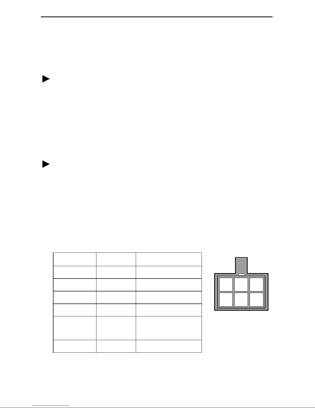
Connecting the Unit to an Optional Exter nal +24 or –48 VDC Power
99-16291
23
546
1
Source
Using the DC power cable, the unit is capable of operating on a +24 VDC or –48 VDC
SELV power supply.
Procedure
To use the DC power cable for +24 VDC:
1. Connect the green wire to a suitable ground.
2. Connect the orange wire to the +24 VDC source.
3. Connect the white wi re t o the re turn.
4. Cut the black, red, and blue wires off at the outer insulation.
5. Plug the power connector into the unit.
Procedure
To use the DC power cable for –48 VDC:
1. Connect the green wire to a suitable ground.
2. Connect the orange wire to the –48 VDC source.
3. Connect the b lack wire to the return.
4. Cut the red, white, and bl ue wires off at the outer insulation.
5. Plug the power connector into the unit.
Power Cable Pinouts
Pin Number Wire Color Signal
1Black–48 VDC Return
2Red–48 VDC Return
3 Green Ground
4 White +24 VDC Return
5 Orange –48 VDC
+24 VDC
6 Blue No Connection
3
Page 4

Connecting to the Network
Procedure
To connect your unit to the network:
1.
Connect one end of the supplied 8-position-modular-to- 8-position-modular network
cable into the rear panel DSL jack .
2.
Connect the other end to your DSL network interface.
NOTE:
not
Do
performance of the unit. Use only Cat 5 twisted-pair network cab le.
use a flat VF network cable as this may severely degrade the
Connecting to a DTE
Model DTE Connection
7974 The DSX-1 interface is an RJ48C, 8-position, unkeyed modul ar connector.
An RJ48C-to-DB15 T1 network inter face adapter cable is availab le from
Paradyne.
7975 The synchrono us int erf ac e is a 25-pi n EIA-5 30-A interface. Depending on the
cable used, the interface can be adapted to an X.21, RS-449, or V.35
interface.
7976 The G.703 interf ac e is either two BNC conne ctors (Transmit and Recei ve ) fo r
a 75-ohm unbalanced interface or an RJ48C, 8-position, unkeyed modular
connector f or a 120-ohm balanced i nterface .
Connectors, Cables, and Pin Assignments
See
the connectors and cables.
in the User’s Guide for specificat ions of
4
Page 5

LEDs
The fol lowing table contains a description of the LEDs on the Hotwire 797x Standalone
Termination Unit’s front panel .
Label Color LED is . . .*
POWER Green On
Off
Slow Cyclin g
ALARM Red O n
Off
TEST Yellow On
Off
Slow Cyclin g
DSL Green On
Off
Slow Cyclin g
Fast C ycling
Indicating . . .
Normal operation.
No power to the unit.
Unit is in minimum mode and a download is
required.
Device failure, or self-test has failed.
Self-test pass ed.
Loopback test or 511 test pattern in progress.
No tests in progress.
Self-test in progress.
DSL link is up.
The DSL link is down.
DSL training in progress.
An OOF condition.
DSX-1
DTE
G.703
* Slow Cycling: LED tu rns off and on in equal duration once per second.
Fast Cycling: LED turns off and on in equal duration 5 times per second.
Pulsing: LED turns off momentari ly once per second.
Green On
Off
Slow Cyclin g
Fast C ycling
DTE port is operational.
DSX-1: No signal on DTE port.
Sync DTE: Conf igur ed contr ol l eads (DTR/R TS)
are not asserted.
G.703: No signal on DTE port.
DSX-1: Yellow Alarm Indication received.
Sync DTE: Not applicable.
G.703: Remote Alarm Indication receiv ed.
DSX-1: OOF, LOF, EER, or AIS condition.
Sync DTE: Not applicable.
G.703: OOF, LOF, EER, or AIS condition.
5
Page 6

Connecting to a System Terminal
An optional system maintenance terminal may be attached to your Hotwire 797x
Standalon e Termination Unit through the modular jack on the rear panel . The system
maintenance terminal allows you to vi ew the status of the unit and chan ge configuration
options . The terminal must be a VT100-compatible terminal or a PC running terminal
emulati on software.
Procedure
To connect your unit to a system terminal:
1. Connect the 9-pin end of the supplied terminal cab le into a COM port on your PC.
2. Plug the other end in to the modular jack on the rear panel.
3. Set the communication parameters on your PC or terminal to:
— 9600 baud
— 8 bit char acters
— no parity
— 1 stop bit
— no flow control
Press E n te r fr o m your te r m inal or P C to act iva te th e Ma in M en u for the at ta c h ed un i t.
The system runs di agnost ics and st atu s check s. Aft er a f e w moment s, th e Main Men u or
Logon screen appears on your terminal .
main Hotwire
Model 797x
MAIN MENU
Status
Test
Configuration
Control
----------------------------------------------------------------------------Ctrl-a to access these functions E
xit
6
Page 7
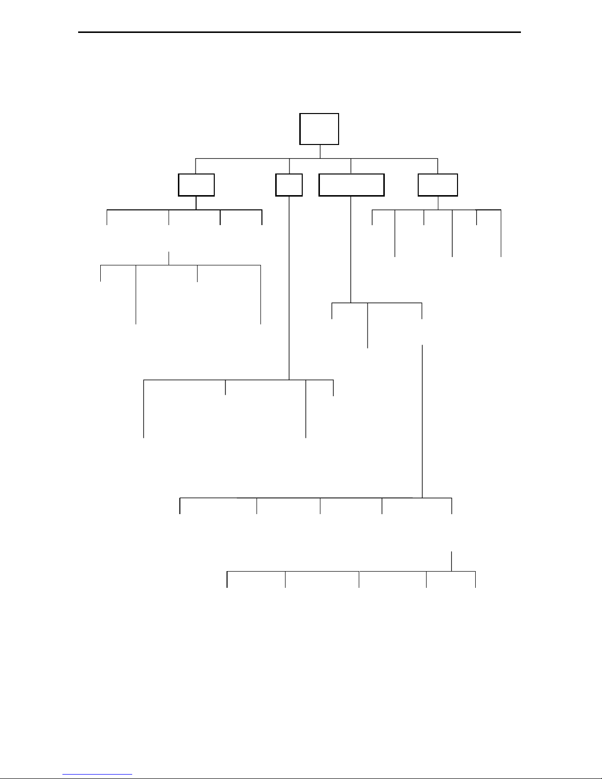
Asynchronous Terminal Interface Menu
The following illustration shows the menu paths to the different terminal screens.
Main
Status Test
System and
Test Status
Network
Error
Statistics
Performance
Display
Statistics
7974: DSX-1 Statistics
7975: (Not Applicable)
7976: G.703 Statistics
Network
Performance
Statistics
7974: (Not Applicable)
7975: Sync Data Port Tests
7976: (Not Applicable)
7974: Network and DSX-1 Tests
7975: Network Tests
7976: Network and G.703 Tests
LEDs
Performance
Identity
Current
Network
Factory
Device
Tests
Configuration Control
Change
Identity
Administer
Download
Logins
Code
Apply
Download
Current Configuration
Config
Edit/Display
Configuration
Loader
Abort
All
Tests
Reset
AutoRate
Reset
Device
Network
7974: DSX-1
7975: Sync Port
7976: G.703
Telnet
Communication
Session
Protocol
7
System
Options
General SNMP
Management
Communication
Port
SNMP NMS
Security
Management
and
Communication
SNMP
Traps
01-16496-03
Page 8

Entering Identity Information
After acce ssing your unit f or the first time, use the Change Identit y screen to determine
SNMP administrative system informati on that will be displ ayed on the Identity screen of
the Status branch. To access the Identi ty screen, f oll ow this menu selection sequence:
Main Menu → Control → Change Identity
Selecting a C onfigur ation Method
You can make configuration changes either throu gh a VT100-compatibl e terminal and
the unit’s Configuration menus or by manually changing switches on the board. The unit
is shipped with the switchpacks disabled to allow settings to be made through the
Configuration menus. See the User’s Guide fo r detailed inf ormation about the
configu ration options and switch setti ngs.
Configuring the U nit Using the Configuration Menus
Use the Configuration menu to select, display, or change configuration option settings.
NOTE:
The Hotwir e 797x Standalone Termination Un it is shipped configured as an NTU. If
using this unit as an NTU, the confi guration options may not need to be altered.
The unit has two sets of configuration option settings:
The Current Configuration: The unit’s active set of configurat ion options.
The Defaul t Factory Configuration: A read- only configu ration area containing the
factory default configuration options.
8
Page 9
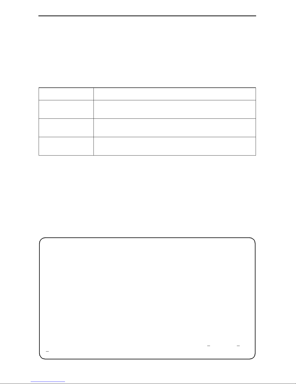
Displaying Configuration Opti ons
To display configuration options, you must fi rst load a configuration into the edit area. To
load a conf igur ation o ption s et int o the conf igur atio n edit ar ea, follow this menu sel ecti on
sequence:
Main Menu → Configuration (Load Configuration F rom)
Make a selection by placing the cursor at your choice and pressing Enter.
If you select . . . Then . . .
Current
Configuration
Default Factory
Configuration
Configuration
Loader
The selected configuration opti on set is loaded and the
Configurati on Edit/Display menu screen appear s.
The selected configuration opti on set is loaded and the
Configurati on Edit/Display menu screen appear s.
The Configurati on Loader screen is displayed al lowing you to
upload or download configurations from a TFTP server.
Configuration Edit/Display
The Configuration Edit/Dis play screen is displayed when the current or default
configuration is loaded. To access the Configuration Edit/Display screen, follow this
menu selection sequence:
Main Menu → Configuration → Current Configuration
– or –
Main Menu → Configuration → Default Factory Configuration
main/config/edit
Model: 797x
CONFIGURATION EDIT/DISPLAY
Network
DSX-1 | SYNC Port | G.703
System Options
Communication Port
Management and Communication
----------------------------------------------------------------------------Ctrl-a to access these functions, ESC for previous menu MainMenu Exit
ave
S
9
Page 10

Select . . . To Access the . . . To Configure th e . . .
Network Network Interface Options (Table 1) DSL network interface on
the unit.
DSX-1
SYNC Port
G.703
DSX- 1 In te r fac e Op tio n s – Model
7974 (Table 2)
Synchronous Dat a Port Options –
Model 7975 (Table 3)
G.703 Inter face Options – Model
7976 (Table 4)
DSX-1 interface
(Model 7974)
Synchronous DTE interface
(Model 7975)
G.703 interface
(Model 7976)
System Options System Options (Table 5) General system options of
the unit.
Communication
Port
Management
and
Communication
Communica ti on Port Options
(Table 6)
Telnet Session Options (Table 7)
Communication Protocol Options
(Table 8)
General SNMP Managem ent
Unit’s COM port options.
Management support of the
unit through SNMP and
Telnet.
Options (Table 9)
SNMP NMS Security Options
(Table 10)
SNMP Traps Options (Table 11)
10
Page 11

Table 1. Network Interface Options (1 of 2)
Margin Threshol d
Possible Settings: –5db, –4db, –3db, –2db, –1db, 0db, 1db, 2db, 3db, 4db, 5db,
6db, 7db, 8db, 9db, 10db
Default Sett ing: 0db
Determines the level, expressed in decibels, at which a signal-to-noise margin alarm
condition is reported.
Excessive Error Rate Threshold
Possible Settings: 1E–4, 1E–5, 1E–6 , 1E–7, 1E–8, 1E–9
Default Sett ing: 1E–6
Determines the error rate at which an excessive error rate (EER) condition is
recognized. The rate is the ratio of the number of CRC errors to the number of bits
receiv ed in a certain period.
AutoRate
Possible Settings: Enable, Disable
Default Sett ing: Disable
Determines whether the uni t aut om atically adjus ts t o the best line rate for conditions,
or is fixed at the rate in the DSL Line Rate field.
DSL Line Rate
Possible Settings (depends on model) : 144, 272, 400, 528, 784, 1040, 1552, 2064
Default Sett ing (Model 7974): 1552
Default Sett ing (Model 7975, 7976): 2064
Determines the fix ed line rate of the LTU when AutoRate is di sabled.
Max DSL AutoRate
Possible Settings (depends on model) : 144, 272, 400, 528, 784, 1040, 1552, 2064
Default Sett ing (Model 7974): 1552
Default Sett ing (Model 7975, 7976): 2064
Determines the maximum rate to which the unit can AutoRate.
11
Page 12

Table 1. Network Interface Options (2 of 2)
EIA-530 Pa yload Rate
Possible Settings (Model 7974) : 64, 128, 256, 384, 512, 768, 1024, 1536
Default Sett ing: [Highest multiple of 64 Kbps supported by the DSL Line Rate]
Possible Settings (Model 7976): 64, 128, 192, 256, 320, 384, 448, 512, 576, 640,
768, 960, 1024 , 1536, 1920, 1984, 2048
Default Sett ing: [Highest multiple of 64 Kbps supported by the DSL Line Rate]
When the NTU has an EIA-530-A interface, the Payload Rate set on the LTU
determines the port speed of the synchronous port of the NTU.
To achieve the payload rates listed above, th e Model 7975-A2 endpoint mus t be
operating wit h firmwar e V02.03. 2 or great er and the Model 7976-A2 endp oin t must be
operating with firmware N02.03.2 or greater. In lower firmware versions (N.02.03.05
and below), the pa yl oad rat e is only select ab le at a DSL line ra te of 144 Kbps while al l
other rates default to the maximum, dependi ng on the DSL line rate selected.
Transmit Attenuation
Possible Settings: 0dB – 15dB
Default Sett ing: 0dB
Determines how much the unit ’s transmit power is reduced to accommodate a short
line length.
Peer IP Address
Possible Settings: 001.000.000.000 – 223.255.255.255, Clear
Default Sett ing: 000.000.000.000
When configured as the LTU, specifies the peer IP addres s for the NTU, to provide
remote management providing the remot e man agem ent link on the DSL loop.
Circ ui t Id e n ti fier
Possible Settings:
ASCII text field
, Clear
Default Sett ing: [blank]
Uniquely identi fies the circuit num ber of the transmission vendor’s D S L li ne for
troubleshooting purposes.
12
Page 13

Table 2. DSX-1 Interface Options – Model 7974
Line Coding
Possible Settings: AMI, B8ZS
Default Sett ing: B8ZS
Specifies the line coding format to be used by the DSX-1 interface.
Line Framing
Possible Settings: ESF, D4
Default Sett ing: ESF
Specifies the fram ing format to be used by t he DSX-1 interface.
Line Equalization
Possible Settings: 0–133, 133–266, 266–399, 399 –533, 533–655
Default Sett ing: 0–133
Compensates for signal dist ortion for a DSX-1 signal over a given distance.
Excessive Error Rate Threshold
Possible Settings: 1E–4, 1E–5, 1E–6, 1E –7, 1E–8, 1E–9
Default Sett ing: 1E–4
Determines the error rate at which an excessive error rate (EER) condition is
recognized. The rate is the ratio of the number of CRC errors to the number of bits
receiv ed in a certain period.
Send (AIS) on Network Failure
Possible Settings: Enable, Disable
Default Sett ing: Enable
Specifies the act ion taken on the signal transmitted to the DSX when a v alid signal
cannot be recovered from the network interface (LOS or cognition s OOF, AIS, or
EER).
Primary Clock Source
Possible Settings: DSX, Internal
Default Sett ing: Internal
When configured as the LTU, specifies from where the unit will derive its timing.
13
Page 14

Table 3. Synchronous Data Por t Options – Model 7975 (1 of 2)
Port Type
Possible Settings: E530A, V.35, RS449, X.21
Default Sett ing: E530A
Determines the port type for the data port.
NOTE: If X.21 is selected for Port Type, set Send All Ones on Data Port Not Ready
to RTS or Disable.
Payl oa d Rate
Possible Settings: 64, 128, 192, 256, 320, 384, 448, 512, 576, 640, 704, 768 , 832,
896, 960, 1024, 1088, 1152, 1216, 1280, 1344, 1408, 1472, 1536, 1600, 1664,
1728, 1792, 1856, 1920, 1984, 2048
Default Sett ing: [Highest multiple of 64 Kbps sup ported by the DSL Lin e Rate]
Specifies the payload rate of the port. This option is not displayed on the unit when
AutoRate is enabled or the unit i s configured as an NTU. The LTU configures the
payload rate for the NTU. The highest multiple of 64 Kbps is used when Autorate is
enabled.
NOTE: Payload rates of 1088 Kbps and higher pertain only to 2 Mbps models.
Transmit Clock Source
Possible Settings: Inte rnal, External
Default Sett ing: Internal
When configured as the LTU, spec if ies whether the trans mitted data for the
synchronous data port is clocked using an internal clock pro vided by the LTU or an
external clock provided by the DTE connected to the synchronous data port.
Invert Transmit Clock
Possible Settings: Disable, Enable
Default Sett ing: Disable
When configured as the LTU and T ransmit Clock Source is set to External, specifies
whether the clock supplied by the t he unit on the TXC interchange circ uit DB
(ITU-T 114) is phase inv erted with respect to the Transmitted Data interchange circuit
BA (ITU-T 103). This configuration option is useful when an excessive cable length
between the unit and the DTE causes errors.
14
Page 15

Table 3. Synchronous Data Por t Options – Model 7975 (2 of 2)
Send All Ones on Data Port Not Ready
Possible Settings: Both, Disable, DTR, RTS
Default Sett ing: Both
Specifies the conditions on the data port that determine when v alid data is not being
sent from the DTE. When this condition is detected, all ones are sent to the netw ork.
NOTE: Set Send All Ones on Data Port Not Ready to RTS or Disab le if X.21 is
selected f or Port Type.
Action on Network LOS Alarm
Possible Settings: Halt, None
Default Sett ing: Halt
Specifies the action taken on the synchronous data port when an LOS (Loss Of
Signal) alarm is received on the network interface.
Network Initiated Data Channel Loopback
Possible Settings: Disable, Enable
Default Sett ing: Disable
Allows the initi ation and termination of a Data Channel Loopback (DCLB) by the
receipt of a DCLB-actuate sequence or DCLB-releas e sequence from the network or
far- end device.
Port (DTE) Init iat ed Loopbacks
Possible Settings: Disable, DTLB, DCLB, Both
Default Sett ing: Disable
Allows the ini ti ation and termination of a local Data Terminal Loopback (DTLB) or
remote Data Channel Loopback (DCLB) by the DTE connect ed to this port. (DTLB is
equival ent to a V.54 loop 3, and DCLB is equiv alent to a V.54 loop 2.) Control of these
loopbacks is through the DTE interchange circuits as spec if ied by the V.54 standard.
ElasticStore
Possible Settings: Disable, Enable
Default Sett ing: Enable
When configur ed as the LTU, used to ena b le o r disab le a f irst -in, f irst -out ( FIFO) b uff er
circuit for the incoming external clock. This circuit is us ed to compensate for the
differences between the f requencies of the data cl ocks for t he two units in the circu it .
This option only appl ies if the unit is set f or external ti ming. Do not enable Elastic
Store if the attached DCE has an elastic store buffer larger than 32 bits.
15
Page 16

Table 4. G.703 Interface Options – Model 7976
Framing
Possible Settings: Framed, Unframed
Default Sett ing: Framed
Specifies whether G.704 framing is used for the G.703 interface.
Line Coding
Possible Settings: AMI, HDB3
Default Sett ing: HDB3
Specifies the line codi ng format to be used by the G.703 interface.
Line Framing
Possible Settings: CRC4, noCRC4
Default Sett ing: noCRC4
Specifies the fram ing format to be used by the G.703 interface.
Time Slot 16
Possible Settings: Signaling, Data
Default Sett ing: Signaling
Specifies whether the G.703 interface is used fo r voice or data.
Send (AIS) on Network Failure
Possible Settings: Enable, Disable
Default Sett ing: Enable
Specifies the action taken on the signal transmitted to the G.703 when a valid signal
cannot be recovered from the network interface (LOS or condition s OOF, AIS, or
EER).
Primary Clock Source
Possible Settings: G.703, Internal
Default Sett ing: Internal
Specifies fro m where the uni t will derive its t imi ng.
16
Page 17

Table 5. System Options
DSL Mode
Possible Settings: LTU, NTU
Default Sett ing: NTU
Controls whether the unit is configured as a control unit or tributary unit.
NOTE: Changing this option will reset the uni t.
Test Timeout
Possible Settings: Enable, Disable
Default Sett ing: Enable
Allows tests t o end automatically. The feature should be enabled when the unit is
remotely managed so that control can be regained after a test is accidentally
executed.
Test Dura ti o n (m in )
Possible Settings: 1 – 120
Default Sett ing: 10
Number of minutes for a test to be active before aut om atically ending.
Telco Initiated Loopbac k
(Model 7974)
Possible Settings: Enable, Disable
Default Sett ing: Enable
Determines if the unit will r espond to loopback comman ds on the DSX-1 interfac e.
Remote Telco Line Loopback
(Model 7974)
Possible Settings: Enable, Disable
Default Sett ing: Disable
Determines if the unit will perform a Telco-initi ated loopback on just the local unit or if
the loopback will be performed on the remote DSL unit.
G.703 Line Termination
(Model 7976)
Possible Settings: 75 ohms, 120 ohms
Default Sett ing: 120 ohms
Specifies which G.703 connection’s are being used by the unit, the 75 ohm TX and
RX connectors or the 120 ohm interface.
17
Page 18

Table 6. Communication Port Options (1 of 2)
Port Use
Possible Settings: Terminal, Net Link
Default Sett ing: Terminal
Specifies how the communications port is to be used.
Port Type
Possible Settings: Asynchronous, Synchronous
Default Sett ing: Asynchronous
When Port Use is set to Net Link, P ort Type controls whether t he com m unication port
will be asynchronous or synchronous.
Data Rate
Possible Settings: 9.6, 14.4, 19.2, 28.8, 38.4, 57.6, 115.2
Default Sett ing: 9.6
Specifies the communication port baud rate.
Character Length
(Terminal Use Only)
Possible Settings: 7, 8
Default Sett ing: 8
Determines the character length of the communi cation port.
Parity
(Terminal Use Only)
Possible Settings: None, Odd, Even
Default Sett ing: None
Specifies the parity of the communication port.
Stop Bits
(Terminal Use Only)
Possible Settings: 1, 1.5, 2
Default Sett ing: 1
Specifies the number of stop bits f or the communicati on port.
18
Page 19

Table 6. Communication Port Options (2 of 2)
Ignore Control Leads
(Terminal Use Only)
Possible Settings: Disable, DTR
Default Sett ing: Disable
Specifies whether DTR is used.
Login Required
(Terminal Use Only)
Possible Settings: Enable, Disable
Default Sett ing: Disable
Specifies whether an ID and passwor d are required to access the asynchronous
terminal interface on the communication port. Login IDs are created with a password
and access level.
Port Access Level
(Terminal Use Only)
Possible Settings: Administrator, Operator
Default Sett ing: Administrator
Specifies the highest level of access allowed when accessing an ATI session through
a Telnet session.
Inactivity Ti meo ut
(Terminal Use Only)
Possible Settings: Enable, Disable
Default Sett ing: Disable
Provides automatic logoff of a Telnet session.
Disconnect Time (Minutes)
(Terminal Use Only)
Possible Settings: 1 – 60
Default Sett ing: 5
Number of minutes of i nactivity before the session terminates automatically. Timeout
is based on no keyboard activity.
19
Page 20

Table 7. Telnet Session Options
Telnet Session
Possible Settings: Enable, Disable
Default Sett ing: Enable
Specifies if the unit will respond to a Telnet session re quest from a Telnet cli ent on an
interconnected IP network.
Telnet Login Required
Possible Settings: Enable, Disable
Default Sett ing: Disable
Specifies whether a user ID and pass w ord are requ ired to acc ess to the ATI through a
Telnet session. Login IDs are created with a password and access level.
Session Access Level
Possible Settings: Administrator, Operator
Default Sett ing: Administrator
The Telnet session access level is interrelated with the access level of the Login ID .
Inactivity Ti meo ut
Possible Settings: Enable, Disable
Default Sett ing: Disable
Provides automatic logoff of a Telnet session.
Disconnect Time (Minutes)
Possible Settings: 1 – 60
Default Sett ing: 5
Number of minutes of u ser inactivity before a Telnet session terminates automatica ll y.
Time out is based on no keyboard activity.
20
Page 21

Table 8. Communication Protocol Options
Node IP Address
Possible Settings: 001.000.000.000 – 223.255.255.255
Default Sett ing: 000.000.000.000
Specifies the Node IP add ress.
Node Subnet Mask
Possible Settings: 000.000.000.000 – 255.255.255.255
Default Sett ing: 000.000.000.000
Specifies the Node Subnet Mask.
Default Network Destination
Possible Settings: None, COM, DSL
Default Sett ing: None
Specifies where th e default management network is connecte d. For exampl e, if your
defaul t network is connected to the COM port, select COM as the default
management network destination.
Communication Port IP Address
Possible Settings: 001.000.000.000 – 223.255.255.255
Default Sett ing: 000.000.000.000
Specifies the unit’s Communication Port IP Address when the unit is configured as a
network communic ation link.
Communication Port Subnet Mask
Possible Settings: 000.000.000.000 – 255.255.255.255
Default Sett ing: 000.000.000.000
Specifies th e unit ’s Communicat ion Port Subnet Mask wh en the u nit i s conf igured as a
network communic ation link.
Communication Port Link Protocol
Possible Settings: PPP, SLIP
Default Sett ing: PPP
Specifies the unit’s Communication Po rt link lay er protoco l when the unit is configur ed
as a network communication link.
21
Page 22

Table 9. General SNMP Management Options
SNMP Management
Possible Settings: Enable, Disable
Default Sett ing: Disable
Enable or disables the SNMP management features.
Community Name 1
Possible Settings:
ASCII text field
, Public
Default Text: Public
Identifies the name of the community allowed to access the unit ’s MIB. The
community name m ust be supplied by an external SNMP manager when that
manager attempts to access an object in th e MIB.
Name 1 Access
Possible Settings: Read, Read/Write
Default Sett ing: Read/Write
Determines the access level for Community Name 1.
Community Name 2
Possible Settings:
ASCII text field
, Public
Default Text: (null string)
Identifies the name of the second community allowed to access the unit’s M IB. The
community name m ust be supplied by an external SNMP manager when that
manager attempts to access an object in th e MIB.
Name 2 Access
Possible Settings: Read, Read/Write
Default Sett ing: Read
Determines the access level for Community Name 2.
22
Page 23

Table 10. SNMP NMS Security Options
NMS IP Validation
Possible Settings: Enable, Disable
Default Sett ing: Disable
Specifies whether security check ing is performed on the IP addr ess of SNMP
management system s attempting to access the node.
Number of Managers
Possible Settings: 1, 2, 3, 4, 5, 6, 7, 8, 9, 10
Default Sett ing: 1
Specifies the number of SNMP management systems that can send SNMP
messages.
NMS n IP Address
Possible Settings: 001.000.000.000 – 223.255.255.255, Clear
Default Sett ing: 000.000.000.000
Specifies the In ternet Prot ocol address used to identify each SNMP trap manag er.
Access Level
Possible Settings: Read, Read/Write
Default Sett ing: Read
Determines the access le vel allowed for an authorized NMS when IP address
validation is being performed.
23
Page 24

Table 11. SNMP Traps Options
SNMP T raps
Possible Settings: Enable, Disable
Default Sett ing: Disable
Controls the generation of SNMP trap messages.
Number of Trap Managers
Possible Settings: 1, 2, 3, 4, 5
Default Sett ing: 1
Sets the number of SNMP management systems that will receive SNMP traps.
NMS n IP Address
Possible Settings: 001.000.000.000 – 223.255.255.255, Clear
Default Sett ing: 000.000.000.000
Specifies the In ternet Prot ocol address used to identify each SNMP trap manag er.
NMS n Destination
Possible Settings: DSL, COM
Default Sett ing: DSL
Provides the network destination path of each trap manager.
General Traps
Possible Settings: Disable, Warm, AuthFail, Both
Default Sett ing: Both
Determines which SNMP traps are sent t o each trap manager.
Enterprise Specific Traps
Possible Settings: Enable, Disable
Default Sett ing: Disable
Determines if SNMP traps are generated for enterprise-specific events .
Link Traps
Possible Settings: Disable, Up, Down, Both
Default Sett ing: Both
Determines if SNMP traps are generated for li nk up and link down for one of the
communica ti on interfaces.
Link Traps Interfaces
Possible Settings: Network, [DSX, SYNC, or G.703], All
Default Sett ing: All
Determines if the SNMP
enterpriseSpecific
traps are generated for the network interface, DTE port, or both.
Depending on the model, the DTE option appears as DSX, SYNC, or G.703.
linkUp
, SNMP
linkDown
24
, and interface-related
Page 25

Configuring the Unit Usin g the Internal Switches
Use internal Switchpacks S3 and S4 to manually configure the unit. Use Figure 1,
Hotwire 797x Standa lone Termination Unit Switchpack Loc ations, to lo ca te Sw itc h pac ks
S3 and S4.
!
HANDLING PRECAUTIONS FOR STATIC-SENSITIVE DEVICES
This product is designed to protect sensitive components fr om
damage due to electrostatic discharge (ESD) during normal
operation. When performing installation procedures,
however, take proper static cont rol precautions to
prevent damage to equipment. If you are not sure
of the prope r static control precautions, contact
your nearest sales or service representative.
Procedure
To configure the uni t usi ng internal Switchpac ks S3 and S4:
1. Power off the unit. Remove the enclosure cover by removi ng the two screws at the
top of the unit, then pushing a flat-bl ade sc rewdri ver through the slots on both sides
of the housing to free the four in ner latches.
2. Locate Swi tchpac k S4 on the c ircui t boar d us ing Fi gure 1, Hot wire 797x S tandalo ne
Termination Unit Switchp ack Locations.
3. Set Switch 1 on Switchp ack S4 to ON to enable Switchpacks S3 and S4.
4. After you enable the switchpacks, you must set the swit ches to your desired
configuration. Refer to Figure 1, Hotwire 797x Standalone Termination Unit
Switchpack Locations, and Table 12 through Table 22.
5. Replace and secur e the cover.
6. Power on the board to reset and enable the new configuration.
25
Page 26

Switchpa c k Lo ca tio n s
Use the fo ll owing illustr ation to locate Switchpacks S3 and S4.
Rear
Switchpack
S3 & S4
ON
12345
ON
12345
678
678
ON
12345
ON
12345
S3
678
S4
678
00-16788
Front
Figur e 1. Hotwire 797x Standalon e Termination Unit Swi t chp ack Locations
26
Page 27

Model 7974 Switchpack Definitions
Table 12 through Table 15 list Model 7974 Swit chpack definitions.
Table 12. Switchpack S4 Definitions (Model 7974)
Switch # . . . Allows you to . . .
1 Enable or disable Switchpacks S3 and S4.
OFF = Switchpacks Disabled
ON = Switchpacks Enabled
2 Not used
3 Select the unit’s primary timing sour ce. Valid only for a unit
configured as the LTU.
OFF = Internal Clock
ON = DSX-1 Clock
4 Control the unit’s T1 line coding.
OFF = B8ZS
ON = AMI
5 Control the unit’s framing format
OFF = ESF
ON = D4
6, 7, 8 Control the unit’s line equaliz ati on. Refer to Table 13, Line
Equalization , Switches 6–8 on Switchpack S4 (Model 7974). The
three swi tches form a binary value used as an index to the table of
equalization values . Off denotes 0 (zero) and On denotes 1 (one).
Default in
Bold
000 (all Off) = 0–133 feet
Table 13. Line Equalization, Switches 6–8 on Switchpack S4 (Model 7974)
Switch Posit ion
876
OFF OFF OFF 0 –133 feet
OFF OFF ON 133 –266 feet
OFF ON OFF 266–399 feet
OFFONON399–533 feet
ON OFF OFF 533 –655 feet
ON OFF ON 0–133 feet
ON ON OFF 0–133 feet
ON ON ON 0–133 feet
Line Equalization
27
Default in
Bold
Page 28

Table 14. Switchpack S3 Definitions (Model 7974)
Switch # . . . Allows you to . . .
Default in
Bold
1 Control whether the unit is an LTU or an NTU.
OFF = NTU
ON = LTU
2 Control whether the uni t aut omatical ly ad justs to th e bes t li ne rat e f or
conditions, or is fix ed at the rate set by Switches S3-3 through S3-5.
OFF = Fixed Rate
ON = AutoRate Enabl e d
3, 4, 5 Control the DSL line rate of the unit . Refer to Table 15, DSL Line
Rate, Switches 3–5 on Switchpack S3 (Model 7974). If AutoRate is
enabled, this swit ch represents the maximum DSL AutoRate val ue.
000 (all OFF) = 1552 Kbps
6 Control whether Telco loopbacks are supported.
OFF = Enabled
ON = Disabled
7 Control whether remote Telco loopbacks are supported.
OFF = Disabled
ON = Enabled
8 Emergency Use Only – Switch between tw o versions of firmware.
The unit has tw o banks of flash memory used to hold executable
firmware. This s witch all ows you to ch ange bet ween the t wo ver sions
of firmware. This sw itch is independent from the position of Switch 1
on Switchpack S4 (switchpack enabl e/disable).
OFF = Curr en t F irmware
ON = Previous Firmware
28
Page 29

Table 15. DSL Line Rate, Switches 3–5 on Switchpack S3 (Model 7974)
Switch Posit ion
543
OFF OFF OFF 1552 Kbps
OFF OFF ON 144 Kbps
OFF ON OF F 272 Kbps
OFF ON ON 400 Kbps
ON OFF OFF 528 Kbps
ON OFF ON 784 Kbps
ON ON OFF 1040 Kbps
ON ON ON 1552 Kbps
DSL Line Rate
Model 7975 Switchpack Definitions
Table 16 through Table 19 list Model 7975 Swit chpack definitions.
Default in
Bold
Table 16. Switchpack S4 Definitions (Model 7975)
Switch # . . . Allows you to . . .
1 Enable or disable Switchpacks S3 and S4.
OFF = Switchpacks Disabled
ON = Switchpacks Enabled
2 Control Sync Port Type.
OFF = EIA -5 3 0, RS-449, or X. 2 1
ON = V.35
3 Select the unit’s timing source. Valid only for a unit config ured as the
LTU.
OFF = Internal Clock
ON = External Clock
4, 5, 6, 7, 8 Control Sync Port Data Rate (refer to Table 17, Selec table Payload
Rates (Model 7975))
NOTE: Switches 4 through 8 are only used when the uni t is
configured as an LTU and AutoRate is disabled.
Default in
Bold
All OFF = 2048 Kbps (1024 Kbps for 1 Mbps units)
29
Page 30

NOTE:
Sync Port and DSL Line Rates can only be selected fr om a unit confi gured as the
LTU (Switchpack S3 #1) with AutoRate disab led (Switchpack S3 #2).
Table 17. Selectable Payload Rates ( Model 7975) (1 of 2)
Switchpack S4 Switch Number Associated
DSL
Sync Port P ayload Rate
2048 Kbps (32 x 64) OFF OFF OFF OFF OFF 2064 Kbps
1984 Kbps (31 x 64) ON ON ON ON ON 2064 Kbps
1920 Kbps (30 x 64) ON ON ON ON OFF 2064 Kbps
1856 Kbps (29 x 64) ON ON ON OFF ON 2064 Kbps
1792 Kbps (28 x 64) ON ON ON OFF OFF 2064 Kbps
1728 Kbps (27 x 64) ON ON OFF ON ON 2064 Kbps
1664 Kbps (26 x 64) ON ON OFF ON OFF 2064 Kbps
1600 Kbps (25 x 64) ON ON OFF OFF ON 2064 Kbps
Line Rate87654
1536 Kbps (24 x 64) ON ON OFF OFF OFF 1552 Kbps
1472 Kbps (23 x 64) ON OFF ON ON ON 1552 Kbps
1408 Kbps (22 x 64) ON OFF ON ON OFF 1552 Kbps
1344 Kbps (21 x 64) ON OFF ON OFF ON 1552 Kbps
1280 Kbps (20 x 64) ON OFF ON OFF OFF 1552 Kbps
1216 Kbps (19 x 64) ON OFF OFF ON ON 1552 Kbps
1152 Kbps (18 x 64) ON OFF OFF ON OFF 1552 Kbps
1088 Kbps (17 x 64) ON OFF OFF OFF ON 1552 Kbps
1024 Kbps (16 x 64) ON OFF OFF OFF OFF 1040 Kbps
960 Kbps (15 x 64) OFF ON ON ON ON 1040 Kbps
896 Kbps (14 x 64) OFF ON ON ON OFF 1040 Kbps
832 Kbps (13 x 64) OFF ON ON OFF ON 1040 Kbps
768 Kbps (12 x 64) OFF ON ON OFF OFF 784 Kbps
704 Kbps (11 x 64) OFF ON OFF ON ON 784 Kbps
640 Kbps (10 x 64) OFF ON OFF ON OFF 784 Kbps
576 Kbps (9 x 64) OFF ON OFF OFF ON 784 Kbps
512 Kbps (8 x 64) OFF ON OFF OFF OFF 528 Kbps
448 Kbps (7 x 64) OFF OFF ON ON ON 528 Kbps
384 Kbps (6 x 64) OFF OFF ON ON OFF 400 Kbps
30
Page 31

Table 17. Selectable Payload Rates ( Model 7975) (2 of 2)
Switchpack S4 Switch Number Associated
DSL
Sync Port P ayload Rate
320 Kbps (5 x 64) OFF OFF ON OFF ON 400 Kbps
256 Kbps (4 x 64) OFF OFF ON OFF OFF 272 Kbps
192 Kbps (3 x 64) OFF OFF OFF ON ON 272 Kbps
128 Kbps (2 x 64) OFF OFF OFF ON OFF 144 Kbps
64 Kbps (1 x 64) OFF OFF OFF OFF ON 144 Kbps
Line Rate87654
NOTE:
The 1 Mbps unit Payload Rate defaults to 1024 Kbps (all OFF).
Table 18. Switchpack S3 Definitions (Model 7975)
Switch # . . . Allows you to . . .
1 Control whether the unit is an LTU or an NTU.
OFF = NTU
ON = LTU
2 Control enabling and disabling of the AutoRate capability.
OFF = AutoRate Enabled
ON = AutoRate Disabled
3, 4, 5 Select one of eight p reset DSL line r ates ( ref er to Table 19, DSL Line
Rate, Switches 3–5 on Switchpack S3 (Model 79 75)). If AutoRate is
enabled, DSL Line Rat e represents the A utoRate ceiling.
All OFF = 2064 (1040 for 1 Mbps units)
6 Control enabling and disabling of the Elastic Store feature.
OFF = Elastic Store Enabled
ON = Elastic Store Disabled
7 Not used
Default in
Bold
8 Emergency Use Only – The unit has two banks of flash memory
used to hold executable firmware. This switch allows you to change
between the two versions of firmwar e. This switch i s independent
from the positio n of Switch 1 on Swit chpack S4 (switchpack
enable/disable).
OFF = Current Firmware
ON = Previous Firmware
31
Page 32

Table 19. DSL Line Rate, Switches 3–5 on Switchpack S3 (Model 7975)
Switch Posit ion
543
OFF OFF OFF 2064 Kbps (2 Mbps unit only)
OFF OFF ON 144 Kbps
OFF ON OFF 272 Kbps
OFF ON ON 400 Kbps
ON OFF OFF 528 Kbps
ON OFF ON 784 Kbps
ON ON OFF 1040 Kbps
ON ON ON 1552 Kbps (2 Mbps unit only)
DSL Line Rate
NOTE:
On 1 Mbps units the DSL line r ate defaults to 1040 Kbps (all OFF).
Default in
Bold
32
Page 33

Model 7976 Switchpack Definitions
Table 20 through Table 22 list Model 7976 Swit chpack definitions.
Table 20. Switchpack S4 Definitions (Model 7976)
Switch # . . . Allows you to . . .
Default in
Bold
1 Enable or disable Switchpacks S3 and S4.
OFF = Switchpacks Disabled
ON = Switchpacks Enabled
2 Control line termination.
OFF = 120 Ohm
ON = 75 Ohm
3 Select the unit’s primary timing sour ce. Valid only for a unit
configured as the LTU.
OFF = Internal Clock
ON = External Clock
4 Control the unit’s E1 line coding.
OFF = HDB3
ON = AMI
5 Determine whether the unit will use G.704 framing. Unframed m ode
(ON) is valid only when Switches 3–5 of Switchpack S3 are set to
full ra te (a ll Off).
OFF = Framed
ON = Unframe d
6 Enable CRC-4 generation and monitoring. Valid only for a unit
configured as the LTU. The NTU is automatically configured to
match the LTU setting.
OFF = Disable CRC-4 generation and monitori ng
ON = Enable CRC-4 generation and monitoring
7 Control whether Channel 16 contains signaling info rmatio n or data.
OFF = Channel 16 is used for signal ing (voice mode)
ON = Channel 16 is used for data (data mode)
8 Not used
33
Page 34

Table 21. Switchpack S3 Definitions (Model 7976)
Switch # . . . Allows you to . . .
Default in
Bold
1 Control whether the unit is an LTU or an NTU.
OFF = NTU
ON = LTU
2 Control enabling and disabling of the AutoRate capability. Valid only
for a unit configured as the LTU.
OFF = Fixed Rate
ON = AutoRate Enabled
3, 4, 5 Select one of eight pr eset DSL line rates. Refer to Table 22, DSL
Line Rate, Switches 3–5 on Switchpack S3 (Model 7976). If
AutoRate is enabled, DSL Line Rate represents the AutoRate
ceiling.
All OFF = 2064
6, 7 Not used
8 Emergency Use Only – The unit has two banks of flash memory
used to hold executable firmware. This unit allows you to change
between the two versions of firmwar e. This switch i s independent
from the positio n of Switch 1 on Swit chpack S4 (switchpack
enable/disable).
OFF = Current Firmware
ON = Previous Firmware
Table 22. DSL Line Rate, Switches 3–5 on Switchpack S3 ( Mode l 7976)
Switch Posit ion
543
DSL Line Rate
OFF OFF OFF 2064 Kbps
OFF OFF ON 144 Kbps
OFF ON OFF 272 Kbps
OFF ON ON 400 Kbps
ON OFF OFF 528 Kbps
ON OFF ON 784 Kbps
ON ON OFF 1040 Kbps
Default in
Bold
ON ON ON 1552 Kbps
34
Page 35

!
Importa nt Safety Instruct ions
1. Read and follow all warning notices and instructions marked on the product or
included in the manual.
2. Input power to this product must be provided b y one of t he follo wing: (1) a UL
Listed/CSA Certified power source with a Class 2 or Limit ed Power Source (LPS)
output for use in North America; or (2) a 24 or –48 VDC National Electric Code
(NEC) ANSI/NFPA 70/Canadian Electric Code (CEC) Class 2 circuit installed in
accordance with articles 110-16, 110-17, and 110-18 of the NEC, and articles
2-308, 2 -310, 2-312, 2-314, 2-200, and 2-202 of the CEC , or (3) a Safety Extra Low
V ol tage (SELV) power source with a maximu m av ail abl e output of less than 240 VA,
certified for use in the country of installation.
3. Slots and openings in the cabinet are pro vided for ventilation. To ensure reliable
operati on of the product and to prot ect it from overheating, these sl ots and
openings must not be blocked or covered.
4. Do not allo w any thing to rest on the po we r cord an d do not l ocate t he pr oduct wher e
persons will walk on the power cord.
5. Do not attempt to ins tall or service this product yourself, as opening or removing
covers may expose you to dangerous high voltage points or other risks . Refer all
installation and servicing to quali fied service personnel .
6. General purpose cables are provided with this product. Special cables, which may
be required by the regulatory inspection authority for the installation site, are the
responsibility of the customer.
7. When installed in the final configuration, the product must comply with the
applica ble Safety Standards and regulatory requir em ents of the country in which it
is install ed. If necessary, consult with the appropriate regulatory agencies and
inspection authorities to ensure compliance.
8. A rare phenomenon can create a volta ge potential between t he earth gro unds of
two or more buildings. If products installed in separate buildings are
interconnected, the vol tage potential may cause a hazardous condi ti on. Consult a
qualified electrical consult ant to determine whether or not thi s phenomenon exists
and, if necessary, implement corrective action prior to int erconnecting the products.
9. In addition , if th e equipment is to be used with telecomm unic ations circui ts , tak e the
fol lowing precautions:
— Never install telephone wiring during a lightning storm.
— Never install te lephone jacks in wet locations unless the jack is speci fi cally
designed for wet locations.
— Nev er touch uni nsula ted tel eph one wire s or terminal s unless th e telep hone li ne
has been disconnected at the network interface .
— Use caution when installing or modifying telephone lines.
— Av oi d using a t elephone ( other t han a cordl ess type) during an el ectri cal storm.
There may be a remote risk of electric shock from lightning.
— Do not use the telephone to report a gas leak in the vicinity of the leak.
35
Page 36

EMI Notices
!
UNITED STATES – EMI NOTICE:
This equipment has been tested and found to comply with th e li mits for a
Class A digital de vice, pursuant to Part 15 of the FCC rules. These limits are
designed to pr o vide reas onab le prot ectio n agai nst harmful interf e rence when
the equipment is operated in a commercial environment. This equipment
generates, uses, and can ra diate radio frequency energy and, if not installed
and used in accordance with the instruct ion manual, may cause h arm ful
interference to radio communications. Operation of this equipment in a
resident ial ar ea is l ikel y t o cause ha rmful inte rf eren ce, in whi ch case, t he user
will be required to correct the interference at his own expense.
The authority to operate this equipment is conditioned by the requirements
that no modifications will be made to the equipment unless the changes or
modificat ions are expressl y approved by Paradyne.
!
CANADA – EMI NOTICE:
This Class A digital apparatus meets all requirement s of th e Canadian
interf erence-causing equipm ent regulations.
Cet appareil numéri que de la classe A respecte toutes les exigences du
règlement sur le matériel brouilleur du Canada.
Canada
Notice to Users of the Canadian Telephone Network
The fol lowing notice appl ies to units that have been CS-03 certified and bear the
Industry Canada certification label.
The Industry Canada label identifies certified equipment. This certification means that
the equipment me ets telecommunic ations network protect ive, oper ational and safety
requir ements as prescribed in the appropriate Terminal Equipment Technical
Requirement s document(s). The Department does not guarantee the equip me nt wi ll
operate to the user’s satisfa cti on.
Before installing thi s equipment, users should ensure that it is permissi ble to be
connected t o the facilities of the local telecommunications company. The equipment
must also be installed usi ng an acceptable method of connection. The customer should
be awar e that compliance with the above conditions may not prevent degradation of
service in some situations.
Repairs to certified equip ment should be coord inated by a represent ativ e designat ed b y
the suppl ier. Any repairs or al ter ation s made b y the user to thi s equi pment , or equ ipmen t
malfunctions, may give the telecommunications company cause to request to
disconnect the equipment.
Users should ensure for their own protection that the electrical ground connections of
the power utility, telephone lin es and internal metallic water pipe system, if present, are
connected t ogether. This precaution ma y be particularly important in rural areas.
36
Page 37

CAUTION:
Users should not attempt to make such connecti ons themselves, but should
contact the appropriate electric inspection authority, or electrician, as
appropriate.
The Ringer Equivalence Number (REN) assigned t o each terminal device pr ovides an
indication of the maximum number of terminals allowed to be connected to a telephone
interface. The termin ati on on an interf ace m ay consist of any combination of devices
subject only to the requirement that the sum of the Ringer Equivalence Numbers of all
the devices does not e xceed 5.
If your equipment is in need of repai r, refer to
Information
on page 38.
Warranty, Sales, Service, and Training
CE Marking
When the product is marked with the CE mark, this demonstrates full compliance with
the fo ll owing European Directives:
Directive 72/ 73/ EEC – Council Directiv e of 19 F e bruary 1973 on the h armonizati on
of the laws of the member states relating to electrical equipment designed f or use
within certain voltage limits, as amended by Directiv e 93/68EEC.
Directive 89/336/EEC – Council Directive of 3 May 1989 on the approximati on of
the la ws of the member stat es relating to El ectro-Magnetic Compatibility (EM C), as
amended by Directive 93/68/EEC.
Japan
Class A ITE
This is a Class A produc t based on the standard of the Voluntary Control Council for
interf er ence by In format ion Technology Equipment (VCCI). If this equi pment is used in a
domestic en v ironment , radi o dist urbance ma y arise. When such t roubl e occurs , the user
may be required to take corrective actions.
37
Page 38

Warranty, Sales, Service, and Training Information
Contact y our local sales repr esentativ e, service represent ati ve, or dis tributor directly for
any help needed. For additi onal inf ormati on concerning warranty, sales, service, repair,
installation, documentation, train ing, distributor locations, or Parady ne worl dwide office
locations, use one of the following methods:
Internet:
sure to register your warranty at www.paradyne.com/warranty.)
Telephone:
speak with a company representati ve.
— Within the U.S.A., call 1-800-870-2221
— Outside th e U.S.A., call 1-727-530-2340
Visit the Paradyne Worl d Wide Web site at www.paradyne.com. (Be
Call our automated system to receive current information by fax or to
Document Feedback
We w elcome y our comment s an d suggest ions abo ut this do cument . Plea se mail them to
Technical Publications, Parad yne Corporation, 8545 126th Ave. N., Largo, FL 33773, or
send e-mail to userdoc@paradyne.com. Include the number and title of this docum ent
in your correspondence. Please include your name and phone numbe r if you are willing
to provide additional clarification.
Trademarks
Hotwire is a registered trademark of Paradyne Corpor ati on. All other products and
services mentioned are the trademarks, service marks, registered trademarks, or
registered service marks of their respective owners.
Copyright © 2001 Paradyne Corporation. Printed in U.S.A.
38
Page 39

Page 40

*7900-A2-GN11-20*
 Loading...