

Paradyne FrameServer SLV 9520-ILM Installation Instructions Manual

FrameSaver® SLV 9520-ILM
Installation Instructions
Document Number 9520-A2-GN11-10
January 2003
Contents
Product Documentation Online ..................................................................... 2
Checking the Contents of the Shipping Carton ............................................. 2
Site Preparation Checklist ............................................................................. 3
Installing the FrameSaver SLV 9520-ILM ...................................................... 3
Cables Required ........................................................................................... 4
Mounting the FrameSaver SLV 9520-ILM ..................................................... 5
Connecting to Power ..................................................................................... 7
Connecting the Terminal Cable ..................................................................... 8
Menu Hierarchy ............................................................................................. 9
Power-On Self-Test ....................................................................................... 12
Configuration Using Configuration Edit/Display ............................................ 12
About the Installation Procedures ................................................................. 13
Minimal Installation ....................................................................................... 14
Full Installation and Setup ............................................................................ 16
Automatic Configuration ................................................................................ 17
Connecting to the Network ........................................................................... 17
Configuring SNMP Trap Managers and Traps .............................................. 19
Verifying the End-to-End Path ....................................................................... 19
Connecting the LAN Cable ........................................................................... 20
Connecting to the DTE ................................................................................. 20
Checking that Data is Being Received .......................................................... 22
Checking PVC Connections .......................................................................... 22
Important Safety Instructions ....................................................................... 23
Government Requirements ........................................................................... 25
Warranty, Sales, Service, and Training Information ...................................... 27
Document Feedback ..................................................................................... 27
Trademarks ................................................................................................... 27
Patent Notification ......................................................................................... 27
1

Product Documentation Online
Complete documentation for this product is available at www.paradyne.com.
Select
Select the following documents:
Support →Technical Manuals →FrameSaver Frame Relay Devices.
FrameSaver SLV Technical Description
FrameSaver SLV Configuration Reference
FrameSaver SLV SNMP Reference
FrameSaver SLV Operations Guide
To order a paper copy of a Paradyne document, or to speak with a sales representative,
please call 1-727-530-2000.
Be sure to register your warranty at www.paradyne.com/warranty.
(9000-A2-GB30)
(9000-A2-GB31)
(9000-A2-GB32)
(9000-A2-GB33)
Checking the Contents of the Shipping Carton
In addition to these installation instructions, the shipping carton for your FrameSaver
SLV 9520-ILM should contain:
FrameSaver SLV 9520-ILM
Two DS3 network cables
One power cable for each power supply installed
Two mounting brackets
Installation kit containing machine screws and other hardware
Notify your supplier if anything is missing or damaged.
2

Site Preparation Checklist
Preparation for installation of the FrameSaver SLV 9520-ILM includes the following
steps:
❑ Identify a suitable location for installation:
— Verify that there is a nearby unshared ac power source, preferably from an
Uninterruptable Power Supply (UPS). If a redundant power supply is used,
verify that there is a second source available.
— Verify that there is free vertical space of at least 7 inches (180 mm) in the rack
for each FrameSaver SLV 9520-ILM to be installed. See the
Technical Description (9000-A2-GB30)
— There must be clearance of at least 4 inches (100 mm) at the back of the units
for cabling. Access to the back of the unit is required during installation or when
test equipment is connected to the unit.
— The front of the unit must be visible so that LEDs can be monitored. Access to
the front of the unit is also required in the event the front panel assembly must
be replaced.
— The ambient temperature of the site must be in the range of 0° to 50°C (32° to
122°F).
for the complete dimensions of the unit.
FrameSaver SLV
❑ Determine location of your T3, DTE, LAN, and monitor interfaces.
❑ Procure cables of appropriate types and lengths (see Table 1, Cables Required,
and Table 2, Maximum Cable Lengths).
❑ Install and position the cables for eventual attachment to the FrameSaver SLV
9520-ILM.
Installing the FrameSaver SLV 9520-ILM
Physical installation of the FrameSaver SLV 9520-ILM includes:
Procuring the required cables
Mounting the FrameSaver SLV 9520-ILM in a rack
Connecting to power
Observing the Power-On Self-Test
Before you install the unit, read the
Important Safety Instructions
on page 23.
3

Cables Required
Table 1, Cables Required, shows the cables used with the FrameSaver SLV 9520-ILM.
See the
specifications of the cables.
Table 1. Cables Required
Port Cable Description Quantity Required Supplied
FrameSaver SLV Technical Description (9000-A2-GB30)
for electrical
NET RX,
NET TX
and
CPE RX,
CPE TX
LAN Ethernet 10/100BaseT
Modem RJ11 to RJ11 modular One No
BNC to BNC coaxial Four Two
straight-through cable with
8-pin modular connectors
Ethernet 10BaseT crossover
cable with 8-pin modular
connectors
One (if LAN port is to be
connected to an
Ethernet hub)
One (if LAN port is to be
connected to a Network
Interface Card)
No
No
Maximum Cable Lengths
Table 2, Maximum Cable Lengths, shows the maximum distances for each cable for
which a maximum is specified.
Table 2. Maximum Cable Lengths
Cable Description Maximum Length
Ethernet 10/100BaseT unshielded twisted pair with 8-pin
modular connector
DB25-to-DB25 EIA-232-F for terminal 100 ft (30 m)
328 ft (100 m)
4
Mounting the FrameSaver SLV 9520-ILM
The FrameSaver SLV 9520-ILM can be mounted in a standard 19-inch (483 mm) or
23-inch (584 mm) cabinet or open rails, and either flush with the mounting rails or
approximately 4 inches (100 mm) forward of the rails. The different configurations are
accommodated by positioning two mounting brackets.
The following procedure requires:
A fiber-tip marking pen
A large Phillips screwdriver
Mounting brackets and #8 flathead machine screws
Four self-retaining nuts (for rails with unthreaded holes)
Four #10 machine screws (for use with self-retaining nuts or rails with small
threaded holes)
Four #12 machine screws (for rails with large threaded holes)
The mounting brackets, machine screws, and self-retaining nuts are supplied with the
FrameSaver SLV 9520-ILM.
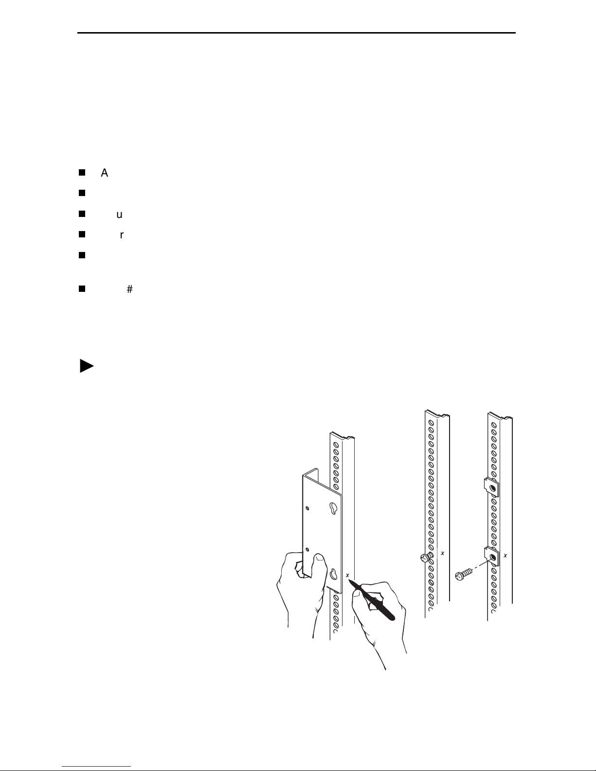
Procedure
To install the FrameSaver SLV 9520-ILM in a standard rack:
1. Determine the general position
of the FrameSaver SLV
9520-ILM in the rack. Hold one
of the mounting brackets in that
position and align it so that the
notches in the keyed holes of
the bracket line up precisely
with holes in the rail.
2. Mark the holes in the rail where
the two machine screws will go.
Then mark the opposite rail in
the same positions.
3. If the rack has threaded holes,
go to Step 4. If the rack does
not have threaded holes, fit
self-retaining nuts over the rails
at the marked holes.
4. Using a large Phillips
screwdriver, put machine
screws at the two bottom screw
positions you marked. Leave
the screws loose enough that
the mounting brackets can slide over them.
98-16023
5
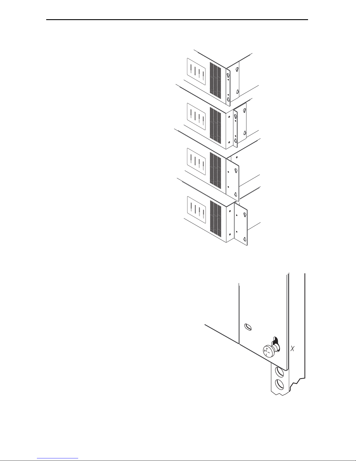
5. Determine the size of the rack in which you are installing the unit.
The brackets must be mounted
with the:
— Wide side of the brackets
against the body of the unit
for a 19-inch (483 mm) rack
— Narrow side of the brackets
against the body of the unit
for a 23-inch (584 mm) rack
Use the screw holes:
— Nearest the front of the unit to
mount it flush with the rails
— Four inches from the front of
the unit to mount it
overhanging the rails (forward
mount)
The keyed holes are at the bottom
of the brackets when they are
positioned correctly.
F
ram
e
S
aver
T
M
SYSTEM
S
LV
OK
9
5
8
ALM
0
XMT
TST
PORT 1
FAN
RCV
LCV
PWR
TD
PORT 2NETWORK
OOF
RD
TD
LO
DSR
S
AIS
R
DTR
D
YEL
DSR
DTR
F
ram
eS
a
ve
T
M
r
SYSTEM
S
LV
OK
9
NETWORK
5
8
A
0
LM
XMT
TST
PORT 1
FAN
RCV
LCV
PWR
TD
PORT
OOF
RD
2
TD
LOS
DSR
AIS
R
DTR
D
YEL
DSR
DTR
F
ram
e
S
av
er
T
M
SYSTEM
S
LV
OK
9
5
8
ALM
0
XMT
TST
PORT 1
FAN
RCV
LCV
PWR
TD
PORT 2NETWORK
OOF
RD
TD
LO
DSR
S
AIS
RD
DTR
YEL
DSR
DTR
F
ra
m
eS
a
ve
T
M
r
SYSTEM
S
L
V
OK
9
5
8
ALM
0
XMT
TST
PORT 1
FAN
RCV
LCV
PWR
TD
PORT 2NETWORK
OOF
RD
TD
LOS
DSR
AIS
RD
DTR
YEL
DSR
DTR
19-inch Rack
Flush Mount
19-inch Rack
Forward Mount
23-inch Rack
Flush Mount
23-inch Rack
Forward Mount
6. Fasten the mounting brackets to
the unit with four #8 flathead
screws.
7. Lift the FrameSaver SLV 9520-ILM into
position in the rack, putting the screws
through the keyed holes of the bracket.
Lower the unit onto the screws.
8. Put a machine screw through the top hole
of each bracket and tighten the screw.
Tighten the bottom screws.
98-16022
98-16024
6
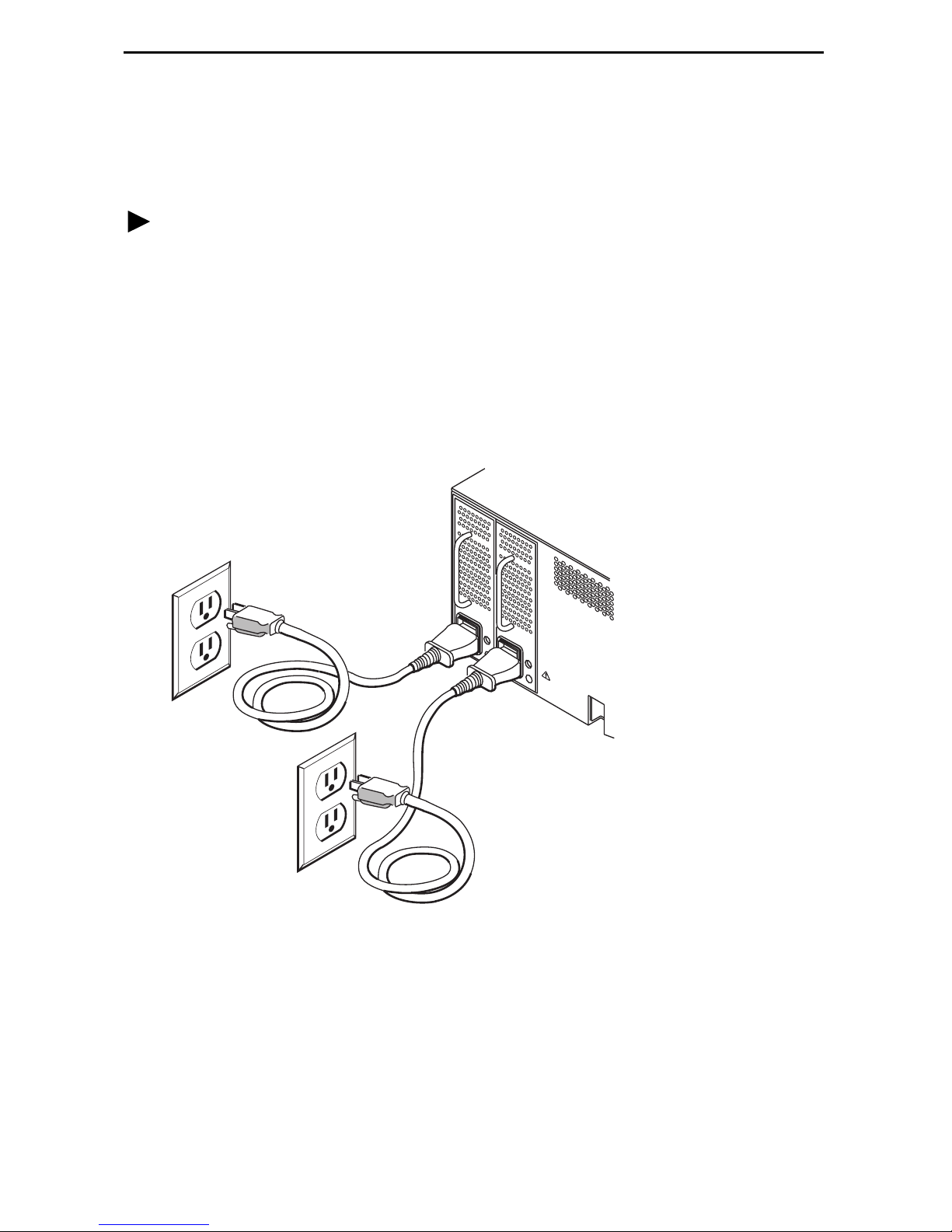
Connecting to Power
The FrameSaver SLV 9520-ILM is powered by redundant power modules. Each is
supplied with a power cable.
Procedure
To install the power cable:
1. Verify that the switch on the power module is in the Off (0) position.
2. Push the 3-hole connector of the power cable into the power receptacle on the back
of the FrameSaver SLV 9520-ILM. Fix the cable to the rail with a cable tie or other
strain relief device.
3. Connect the other end of the power cable to a grounded 110 Vac power source.
4. Push the switch on the power module to the On (1) position.
110 Vac
UPS
LAN
110 Vac
98-16033
If two power modules are used, connect them if possible to separate power sources. If
one power source fails, the FrameSaver SLV 9520-ILM continues to run.
7
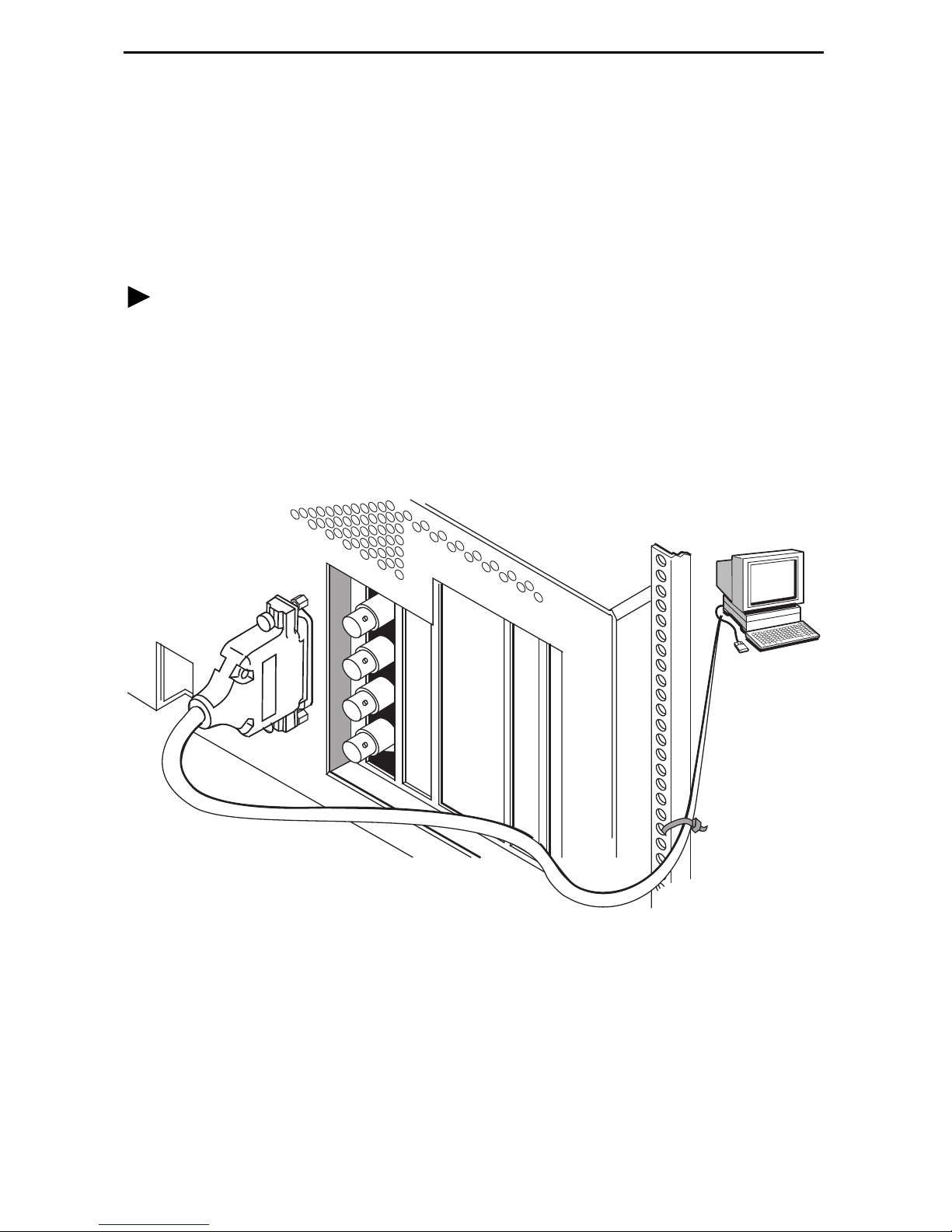
Connecting the Terminal Cable
The TERMINAL PORT on the back of the FrameSaver SLV 9520-ILM can be used to
connect a VT100-compatible terminal or a PC with terminal emulation software. The
port can be protected by access level or password. See the
Configuration Reference (9000-A2-GB31)
for more information.
Connect a terminal or PC to the unit with an EIA-232-F straight-through cable.
Procedure
To install the cable with a terminal or PC:
1. Press the 25-pin connector of the cable onto the TERMINAL PORT socket on the
back of the FrameSaver SLV 9520-ILM. If the cable will be permanently attached,
fasten the connector and fix the cable to the rail with a cable tie or other strain relief
device.
2. Connect the other end of the cable to the serial port of your terminal or PC.
TERMINAL
PORT
LAN
1
2
3
4
5
FrameSaver SLV
3. Verify that the terminal or emulation software is set to:
— 19200 bps
— 8 data bits
— No parity bit
— 1 stop bit
— No flow control
PC or
Terminal
00-16776
8

Menu Hierarchy
The Menu Hierarchy shows the organization of the FrameSaver unit’s screens.
Stat u s
System and Test
Status
LMI Reported
DLCIs
IP Path
Connection Status
PVC Connection
Status
I P R o u t i n g T a b l e Destination
Self-Test Results
Last System Reset
Health and Status
Tes t St a tu s
DLCI
Status
CIR (bps)
Device Name
IP Address
Status
Discovery Source
Source Link, DLCI, EDLCI Status
Primary Destination Status
Alternate Destination Status
Mask
Gateway
Hop
Ty pe
Interface
TTL
Performance
Statistics
T r a p E v e n t L o g Number of Trap Events
Display LEDs and
Control Leads
I d e n t i t y System
Service Level Verification
DLCI
Frame Relay
T3 Network Line
Ethernet
Clear All Statistics
Time of Day
Event
NAM
9
 Loading...