

Paradyne FrameSaver SLV 9626 Installation Manual

FrameSaver
®
SLV 9626
Installation Instructions
Document Number 9626-A2-GN10-40
January 2003
Contents
Product Documentation Online ..................................................................... 2
Upgrading a Unit to the SLM Feature Set ..................................................... 2
Package Checklist ......................................................................................... 2
Preparation ................................................................................................... 3
Cables You May Need to Order .................................................................... 3
Safety Instructions ........................................................................................ 3
Installing the Power Supply and Cord ........................................................... 4
Connecting the COM Port to an Asynchronous Terminal ............................. 5
Verifying that Self-Test Passed ..................................................................... 5
Menu Hierarchy ............................................................................................. 6
A Quick Guide to Configuration .................................................................... 9
About the Installation Procedures ................................................................. 10
Full Installation and Setup ............................................................................ 10
Minimal Installation for Service Providers ..................................................... 13
Setting Up Local Management at the Central Site ........................................ 15
Automatic Configuration ................................................................................ 15
Setting Up the Modem .................................................................................. 16
Setting Up the ISDN DBM ............................................................................ 18
Configuring SNMP Trap Managers and Trap Dial-Out .................................. 21
Connecting to the Network ........................................................................... 22
Verifying the End-to-End Path ....................................................................... 23
Connecting to the DTE (Router or FRAD) .................................................... 24
Connecting the Modem ................................................................................. 25
Connecting to ISDN ...................................................................................... 26
Verifying That Data is Being Received .......................................................... 27
Checking PVC Connections .......................................................................... 27
Verifying That Data Can Be Passed Between DBMs .................................... 28
Connecting the COM Port to the Router ....................................................... 28
Important Safety Instructions ........................................................................ 29
EMI Notices .................................................................................................. 30
Government Requirements ........................................................................... 31
Warranty, Sales, Service, and Training Information ...................................... 34
Document Feedback ..................................................................................... 34
Trademarks ................................................................................................... 34
Patent Notification ......................................................................................... 34
1

Product Documentation Online
Complete documentation for this product is available at www.paradyne.com.
Select
Select the following documents:
Support → Technical Manuals → FrameSaver Frame Relay Devices.
FrameSaver SLV Technical Description
FrameSaver SLV Configuration Reference
FrameSaver SLV SNMP Reference
FrameSaver SLV Operations Guide
To order a paper copy of a Paradyne document, or to speak with a sales representative,
please call 1-727-530-2000.
(9000-A2-GB30)
(9000-A2-GB31)
(9000-A2-GB32)
(9000-A2-GB33)
Upgrading a Unit to the SLM Feature Set
Full Service Level Management (SLM) capability can be activated in units that have the
basic diagnostic feature set at any time. This is an optional feature that adds real-time
and historical network performance monitoring and SLA (Service Level Agreement)
reporting capabilities to your FrameSaver unit and network. Simply order a Feature
Activation Certificate and provide the model to be activated, your OpenLane
system license key number, and the number of FrameSaver units to be activated to SLM
capability. You can order the certificate for a single unit or for many units.
OpenLane SLM Release 5.3 or above is required to schedule activation of SLM features
in units, and to manage the number of activations remaining on the certificate.
OpenLane also provides a Certificate Summary Report to assist you in the management
of the certificate.
®
SLM
When the Feature Activation Certificate arrives, add the Activation Certificate Number to
your OpenLane SLM application’s database. Activations can occur at any time, for as
many units as desired, until no activations remain for the certificate. When ready to
activate units, simply select the units to be activated and schedule the activations. The
activations occur when scheduled, and OpenLane updates the certificate information.
Contact your sales representative for additional information.
Package Checklist
Verify that your package contains the following:
❑ FrameSaver SLV (service level verifier) unit
❑ Power cord with a desktop 120 VAC power transformer
❑ RJ48S modular cable for U.S. network access
❑ RJ49C cable for ISDN DBM interface
Be sure to register your warranty at www.paradyne.com/warranty.
2

Preparation
Make sure you have:
❑ A dedicated, grounded power outlet that is protected by a circuit breaker within
6 feet of the FrameSaver SLV unit
❑ A clean, well-lit, and ventilated site that is free from environmental extremes
❑ One-to-two feet of clearance for cable connections
❑ A physical connection to the frame relay DDS network
❑ An asynchronous terminal or PC (personal computer).
❑ Configuration information for the FrameSaver unit being installed or replaced.
❑ Appropriate cables:
— Data port cable
— COM port-to-terminal or COM port-to-PC cable
— An RJ11 modem cable
See the appropriate manual for additional information.
For troubleshooting, see the
For technical specifications, and connectors, cables, and pin assignments, see the
FrameSaver SLV Technical Description
FrameSaver SLV Operations Guide
Cables You May Need to Order
Model/Feature
If connecting to a . . . Order a . . .
LAN Customer converter with a DB25 plug on
one end and an 8-pin modular jack on
the other end, with a custom 8-conductor
cable and LAN adapter
Contact your sales representative to order cables.
Number
3100-F2-910
Safety Instructions
Please refer to the
Important Safety Instructions
on page 29.
3
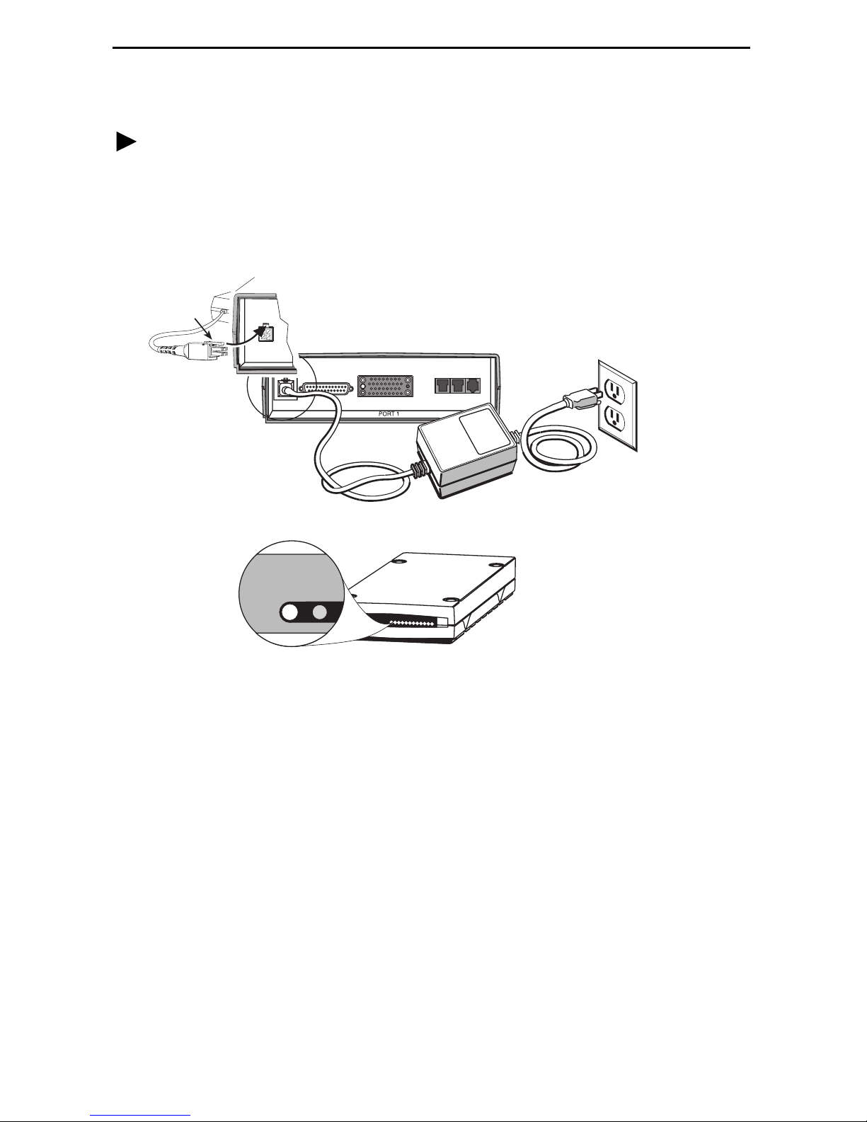
Installing the Power Supply and Cord
Procedure
1. Insert the 4-prong plug into the POWER jack.
When inserting the plug at the rear of the FrameSaver unit, align the plug with the
notch above the POWER jack. Make sure the locking tab snaps securely into the
jack.
Locking
Ta b
Insert the 3-prong plug
2.
into an AC outlet.
POWER
POWER
OK
COM
ALM
NET
DBMMDM
4. Plug the power cord into the grounded power outlet.
If any LEDs light, you have power. If not, refer to
FrameSaver SLV Operations Guide
for possible explanations.
Troubleshooting
Power Cord /
Transformer
3.
The front panel
OK LED lights.
3-Prong
Grounded
AC Outlet
00-16478-01
in the
4
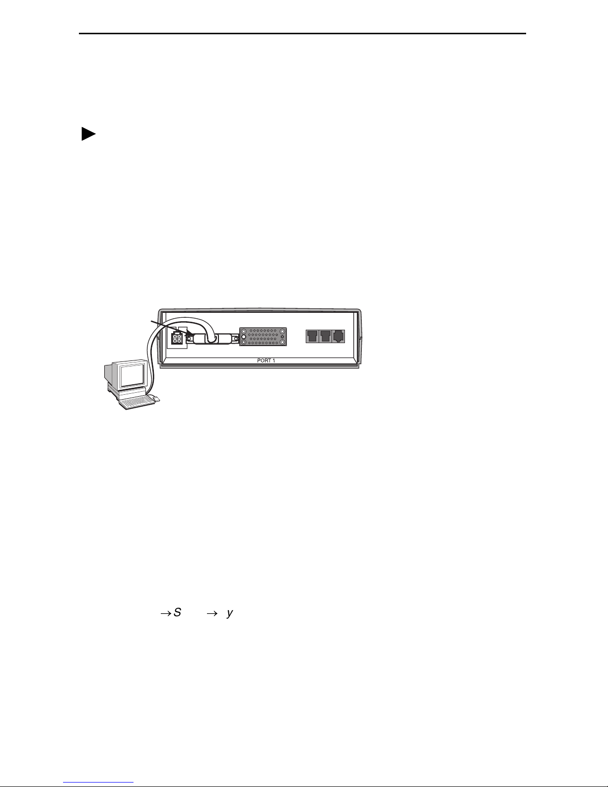
Connecting the COM Port to an Asynchronous Terminal
A VT100-compatible asynchronous terminal or a PC providing VT100 terminal
emulation must be used to set up access to and management of the unit.
Procedure
1. Configure the terminal or PC to be compatible with the FrameSaver unit:
— COM Port in use by your PC: COM1 or COM2.
— COM Port Baud Rate set to 19.2 Kbps.
— Character length set to 8 data bits.
— Parity set to none.
— Stop bit set to 1.
— Flow Control set to None.
2. Insert the DB25 end of the EIA-232 cable into the FrameSaver unit’s COM port.
COM
Por t
POWER
COM
NET
DBMMDM
To Connect to a PC
or Async Terminal
99-16348
3. Insert the other end of the cable into the terminal or PC.
4. Tighten the screws on each side of the connector to secure them.
5. Press Enter on the keyboard to display the Main Menu.
If the Main Menu does not appear, recheck the terminal or PC settings (see Step 1),
or press the Enter key. Refer to
Guide
for other possible explanations.
Troubleshooting
in the
FrameSaver SLV Operations
Verifying that Self-Test Passed
To verify that the unit passed its self-test, go to the System and Test Status screen.
Main Menu→Status→System and Test Status
The results of the self-test appears directly under the screen title.
If any failure messages appear, reset the unit by disconnecting, then reconnecting the
power cord. The unit will perform the self-test again. If the failure reappears, call your
service representative for assistance.
5

Menu Hierarchy
The Menu Hierarchy shows the organization of the FrameSaver unit’s screens.
S ta t u s
System and Test
Status
LMI Reported
DLCIs
IP Path
Connection Status
PVC Connection
Status
Network Interface
Status
DBM Interface
Status
Self-Test Results
Last System Reset
Health and Status
Tes t St a tu s
DLCI
Status
CIR (bps)
Device Name
IP Address
Status
Discovery Source
Source Link, DLCI, EDLCI
Primary Destination Status
Alternate Destination Status
Operating Rate
Loop Loss
Line Status
Link
Link Operating Mode
Call Status
Most Recent Cause Value
Previous Cause Value
Maximum Link Rate
Negotiated Rate
ISDN Channel
Remote Call ID
I P R o u t i n g T a b l e Destination
Performance
Statistics
T r a p E v e n t L o g Number of Trap Events
Mask
Gateway
Hop
Ty pe
Interface
TTL
Service Level Verification
DLCI
Frame Relay
DDS Line
DBM Call
Clear All Statistics
Time of Day
Event
6

Status
continued
Display LEDs and
Control Leads
I d e n t i t y System
NAM
Te st
Configuration
Network PVC Tests PVC Loopback
Send Pattern
Monitor Pattern
Connectivity
Data Port PVC
Tests
Network Physical
Tests
Data Port Physical
Tests
IP Ping
Lamp Test
Abort All Tests
System Frame Relay and LMI
PVC Loopback
Send Pattern
Monitor Pattern
Local CSU Loopback
Local DSU Loopback
Send Pattern
Monitor Pattern
DTE Loopback
PPP
Class of Service Definitions
Service Level Verification
General
Network Physical
Frame Relay
PPP
DLCI Records
Data Ports Physical
Frame Relay
PPP
DLCI Records
PVC Connection
Table
IP Path List Add and Display Static Paths
Management and
Communication
Options
Source Link, DLCI, EDLCI
Primary Destination Link, DLCI, EDLCI
Alternate Destination Link, DLCI, EDLCI
Node IP
Management PVCs
General SNMP Management
Telnet and FTP Sessions
SNMP NMS Security
SNMP Traps
Communication Port
Modem Port
7

Configuration
continued
Auto Backup
Criteria
Auto Backup
DLCI Down Backup Activation Delay
DLCI Down Backup Activation
Transition Threshold
Backup Restoration Delay
When Auto Backup Allowed
AutoConfiguration
Control
Frame Relay Discovery Mode
Automatic Circuit Removal
Automatic Backup Configuration
Modem Call
Directories
System
Information
Administer Logins Login ID
Change Operating
Mode
Select Software
Release
LMI Packet
Capture Utility
Directory Number
Directory Phone Number
Device Name
System Name, Location, Contact
Date
Time
Password
Access Level
Back-to-Back Mode
Standard Mode
Current Release
Alternate Release
Switch & Reset
Capture Interface
Packet Capture Start/Stop
Status
Packets in Buffer
Display LMI Trace Log
Reset Device
Easy Install
Service Type
Node IP Address
Node Subnet Mask
TS Access
Create Dedicated Network Mgmt Link
Ethernet Management Options Screen
DDS Line Rate
8

A Quick Guide to Configuration
The FrameSaver unit should operate using the default (factory-set) configuration
options, with exception to the changes specified in these installation instructions. Refer
to the following table for help in navigating the menus.
Press the . . . To . . .
Esc key Go back one screen or menu level. To see a visual
representation of the menu levels, see
page 6.
Menu Hierarchy
on
Tab key, or
Up (↑), Down (↓),
Left (←) and Right (→)
Arrow keys
Enter or Return key Complete the menu or option selection.
Spacebar Display the next available setting when changing a
As an example, follow these steps to go to the Configuration Edit/Display menu so you
can start setting up the unit.
To load a configuration for editing:
1. From the Main Menu, press the down arrow key twice so the cursor is on
Configuration.
2. Press Enter to display the Configuration menu. The Load Configuration From menu
appears.
3. Press Enter to select Current Configuration (the cursor is already on this selection).
The Configuration Edit/Display menu appears.
Move the cursor from one menu item to the next.
configuration option. All the available settings for an option
appears at the bottom of the screen.
This sequence of steps would be shown as the menu selection sequence:
Main Menu→Configuration
To save a configuration option change:
1. Press Ctrl-a to switch to the function keys area at the bottom of the screen.
2. Ty pe s or S (Save) and press Enter. The Save Configuration To menu appears.
3. Press Enter again to save your changes to the Current Configuration.
4. Press Esc until the Configuration Edit/Display menu reappears to continue
configuring the unit.
Press Ctrl-a, type m (M
In the sections that follow, only the minimum option changes required are included so
you will have a quick and trouble-free installation. See the configuration option tables in
the
FrameSaver SLV Configuration Reference
ainMenu), and press Enter to return to the Main Menu.
for more information.
9

About the Installation Procedures
There are two methods for installing and setting up the FrameSaver unit.
One person can install and set up the unit. If this is the case, see
and Setup
An installer can physically install and set up access to the unit, and the network
.
operation center (NOC) can complete the setup. If this is the case, see
Installation for Service Providers
on page 13.
Full Installation
Minimal
Certain procedures are common to both the full installation and minimal methods. These
procedures (starting with
Setting Up Local Management at the Central Site
on page 15)
are referenced in the full and minimal installation instructions. Refer to them, as needed.
Full Installation and Setup
An Easy Install screen is provided to simplify installation and setup. The Easy Install
feature can be used for the first part of the installation when one person is installing and
setting up the unit from beginning to end.
Easy Install Screen Example
main/easy_install 9626
Device Name: Node A 12/26/2002 23:32
EASY INSTALL
Service Type Frame Relay
Node IP Address: 000.000.000.000 Clear
Node Subnet Mask: 000.000.000.000 Clear
TS Access: DLCI 980
Create a Dedicated Network Management Link
Network1 DDS Line Rate (Kbps): Initialize From Network
Network Initiated DCLB: V.54 & ANSI
DSU Latching Loopback (64CC): Enable
Require DSU Latching Loopback Preamble Enable
--------------------------------------------------------------------------Ctrl-a to access these functions, ESC for previous menu MainMenu Exit
Save
10

It is assumed that frame relay service is turned on at the site.
Procedure
1. Select the Easy Install feature.
Main Menu→Easy Install
2. Enter the Node IP Address and Subnet Mask.
3. Set TS Access to DLCI, then select a DLCI on the network interface that will be
used for the troubleshooting access link.
4. Create a Dedicated Network Management Link, selecting a DLCI for the
management link at the Which DLCI would you like to Create a
Dedicated Network Management Link on? prompt, which will be used by
the NOC to access the unit.
5. Configure the T1 network interface options to match the service provider’s settings.
6. Save the configurations.
7. Install the network cable (see
FrameSaver unit starts discovering DLCIs and network time slots (see
Configuration
The remaining steps are optional, depending upon the application. They are performed
from the Main Menu.
8. If the unit will be enforcing CIR (Committed Information Rate) and EIR (Excess
Information Rate) on network frame relay links, enable Traffic Policing.
on page 15).
Connecting to the Network
on page 22). The
Automatic
Main Menu→Configuration→Network→Frame Relay
You can change other Frame Relay and LMI default settings, if necessary.
9. Configure each interface according to the local management interface (LMI) and
assigned line conditions supplied by the service provider.
Configuration→Network→Frame Relay
Configuration
10. Set up SNMP local management (see
Site
on page 15).
11. Set up the modem, and the Call Directories if trap dial-out is desired (see
Up the Modem
→
Data Ports→Frame Relay
on page 16).
Setting Up Local Management at the Central
Setting
12. If the unit has ISDN backup capability, set up the DBM (see
DBM
on page 18).
13. If SNMP traps are wanted, set up managers, select the desired traps, and configure
trap dial-out if desired (see
page 21).
14. Save the configurations.
15. Verify the entire path from the remote unit to the NMS is functioning (see
the End-to-End Path
Configuring SNMP Trap Managers and Trap Dial-Out
on page 23).
Setting Up the ISDN
on
Verif ying
11
 Loading...