

Paradyne FrameSaver SLV 9x24, FrameSaver SLV 9124, FrameSaver SLV 9624 Installation Instructions Manual

TM
FrameSaver SLV 9x24
1-Slot Unit
Installation Instructions
Document Number 9024-A2-GN10-20
December 1998
Product Documentation on the World Wide Web
We provide complete product documentation online. This lets you search the
documentation for specific topics and print only what you need, reducing the waste of
surplus printing. It also helps us maintain competitive prices for our products.
Complete documentation for this product is available at www.paradyne.com.
Service & Support → Technical Manuals → FrameSaver Frame Relay Devices.
Select
Select the following document:
9024-A2-GB20
FrameSaver SLV 9x24 User’s Guide
To request a paper copy of a Paradyne document:
Within the U.S.A., call 1-800-P ARADYNE (1-800-727-2396)
Outside the U.S.A., call 1-727-530-8623
Before You Begin
If you ordered a wall mounting kit (Feature No. 9001-F1-891) for your 1-slot
FrameSaver unit, install the wall mounting before you start installing the unit. Contact
your sales representative to order this feature.
Before you begin installing the 1-slot FrameSaver unit make sure you have:
A dedicated, grounded power outlet that is protected by a circuit breaker within
6 feet of the FrameSaver SL V (service level verifier) unit.
A clean, well-lit, and ventilated site that is free from environmental extremes.
One to two feet of clearance for cable connections.
A physical connection to the frame relay network.
— T1, if a FrameSaver SL V 9124 unit.
— DDS, if a FrameSaver SLV 9624 unit.
An async (asynchronous) terminal or PC (personal computer) to set up the
FrameSaver unit.
1

Node IP Addresses and Subnet Masks. See your network administrator for this
information.
The DLCI (data link connection identifier) for each end of the PVC (permanent
virtual circuit), provided when the frame relay service was purchased.
T1 time slot assignments, if a FrameSaver SL V 9124 unit.
NOTE:
It is important that you follow the instructions for installing the FrameSaver unit as
they are presented if you are to have a quick and trouble-free installation. Do not
install your cables until instructed to do so.
Safety Instructions
Please refer to the
page 24.
EMI Warnings
and
Important Safety Instructions
Package Checklist
Verify that your package contains the following:
1-Slot FrameSaver SL V unit
Power cord with desktop 120 Vac power transformer
Modular cable for U.S. network access:
— RJ48C (T1) if a FrameSaver 9124 (20 – 6.1m)
— RJ48S (DDS) if a FrameSaver 9624 (14 – 4.3m)
FrameSaver SLV 9x24 Quick Reference
Additional cables may need to be ordered. See
page 3 when ordering cables.
(Document No. 9024-A2-GL10)
beginning on
Cables You May Need to Order
on
2

Cables You May Need to Order
FrameSaver SL V 9x24 units have native interfaces so cables can be purchased
anywhere, with the following exceptions.
Model/Feature/
If connecting to a . . . Order a . . .
Part Number
T1 Line interface/connector
For use in Canada
(
LAN Customer converter with a DB25
External Device
(e.g., a modem)
Contact your sales representative to order cables.
)
T1 line interface cable,
RJ48C-to-CA81A
plug on one end and an 8-pin
modular jack on the other end, with
a custom 8-conductor cable and
LAN adapter
Standard EIA-232-D crossover
cable
3100-F1-510
3100-F2-910
9008-F1-550
3
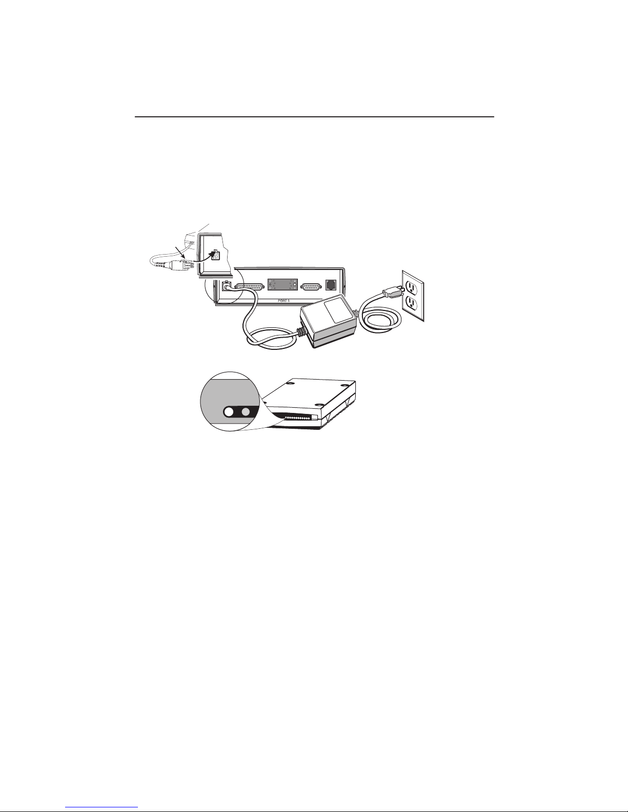
Installing the Power Supply and Cord
1. Insert the 4-prong plug into the POWER jack.
When inserting the plug at the rear of the FrameSaver unit, align the plug with the
notch above the POWER jack. Make sure the locking tab snaps securely into the
jack.
Locking
Tab
POWER
Insert the 3-prong plug
2.
into an ac outlet.
POWER
(FrameSaver 9124
Shown)
COM
DSX-1
NETWORK
Power Cord /
Transformer
3.
The front panel
OK LED lights.
OK
ALM
Verification Check:
Did any LEDs light?
If yes, the FrameSaver unit has power and is operational.
If no, refer to
T roubleshooting Power and COM Port Connections
3-Prong
Grounded
AC Outlet
98-15823
on page 6.
4
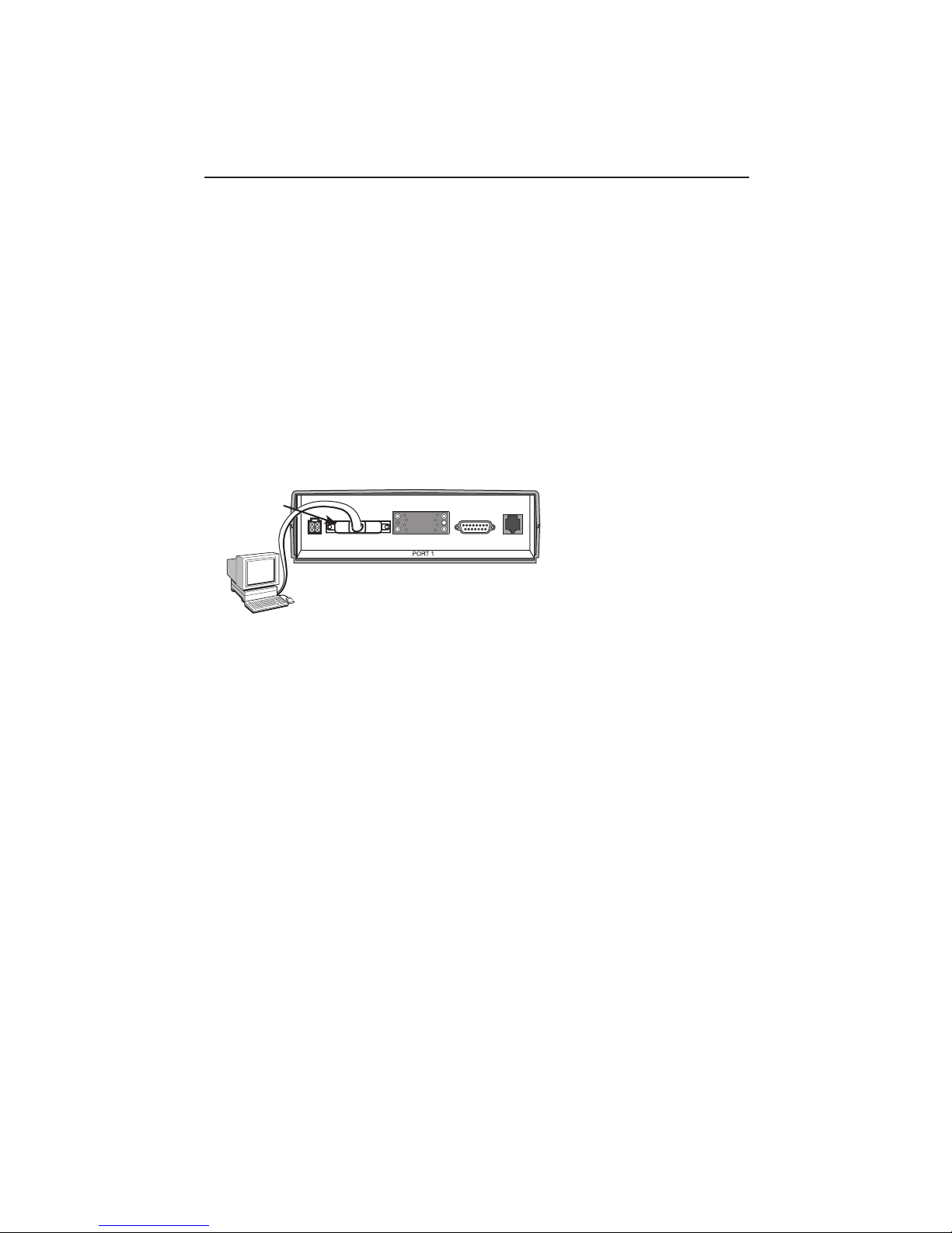
Connecting the COM Port to an Async Terminal
The FrameSaver unit must first be directly connected to a VT100-compatible terminal,
or a PC or async terminal providing VT100 terminal emulation to set up access and
management of the unit.
1. Configure the async or VT100-compatible terminal to be compatible with the
FrameSaver unit:
– COM Port in use by your PC: COM1 or COM2
– COM Port Baud Rate set to 19.2 kbps.
– Character length set to 8 data bits.
– Parity set to none.
– Stop bit set to 1.
– Flow Control set to None.
2. Insert the DB25 end of the EIA-232 cable into the FrameSaver unit’s COM port.
COM
Port
POWER
To Connect to a PC
or Async Terminal
COM
NETWORK
DSX-1
(FrameSaver 9124
Shown)
98-15824
3. Insert the other end of the cable into the VT100-compatible terminal.
4. Tighten the screws on each side of the connector to secure them.
5. Press Enter on the keyboard (or Return, depending upon your keyboard) to display
the Main Menu.
Verification Check:
Did the Main Menu appear?
If yes, you are ready to continue with the installation.
If no,
– Recheck terminal and FrameSaver unit compatibility (see settings in Step 1).
– Did you press the Enter key on your keyboard?
Refer to
T roubleshooting Power and COM Port Connections
possible causes. Refer to
Chapter 13,
T roubleshooting
on page 6 for other
, in the User’s Guide for
additional explanations.
5

Troubleshooting Power and COM Port Connections
Symptom Possible Cause Solutions
No power, or none
of the system LEDs
are lit.
An LED is not lit. LED is burned out. Run the Lamp Test. If the LED in
Power-Up Self-Test
fails. The Alarm
LED is on after
power-up, but the
OK LED is not.
Cannot access the
FrameSaver unit or
the user interface.
Power cord is not
securely plugged into the
wall power outlet or the
universal power supply.
Wall receptacle has no
power.
Power supply is
defective.
The FrameSaver unit has
detected an internal
hardware failure.
Login or password is
incorrect, COM port is
misconfigured, or access
to the FrameSaver unit is
misconfigured.
Check that the power cord is
securely attached at both ends.
1. Check the wall receptacle power
by plugging in some equipment
that is known to be working.
2. Check the circuit breaker.
Contact your sales or service
representative for replacement of
the power supply .
question does not flash with the
other LEDs, contact your sales or
service representative.
1. Reset the FrameSaver unit and
try again.
2. Contact your service
representative.
1. Reset the FrameSaver unit (see
Chapter 12,
Maintenance
2. Contact your service
representative.
Operation and
, the User’s Guide).
6

A Quick Guide to Configuration
The FrameSaver unit should operate using the default (factory-set) configuration
options, with exception to the changes specified in these installation instructions. Refer
to the following table for help navigating the menus.
Press the . . . To . . .
Esc key Go back one screen or menu level. To see a visual
representation of the menu levels, see Menu Hierarchy in
FrameSaver SLV 9x24 Quick Reference
the
.
Tab key, or
Up (↑) and Down (↓)
arrow keys
Enter or Return key Complete the menu or option selection.
Spacebar Display the next available setting when changing a
As an example, follow these steps to go to the Configuration Edit/Display menu so you
can start setting up the unit:
1. From the Main Menu, press the down arrow key twice so the cursor is on
Configuration.
2. Press Enter to display the Configuration menu. The Load Configuration From menu
appears.
3. Press Enter to select Current Configuration, where the cursor is already positioned.
The Configuration Edit/Display menu appears.
This sequence of steps would be shown as the menu selection sequence:
Move the cursor from one menu item to the next.
configuration option. All the available settings for an
option appears at the bottom of the screen.
Main Menu→Configuration→Load Configuration From:→Current Configuration
In the sections that follow, only the minimum option changes required are included so
you will have a quick and trouble-free installation.
7

Installing and Setting Up the FrameSaver SLV
To complete the installation, you must:
Configure the FrameSaver unit.
Connect to the network.
Configure SNMP Trap Managers.
Connect to the DSX, if applicable (T1 units only).
Connect to the DTE equipment.
NOTE:
Follow these instructions as they are presented. Installation time will be increased
if you connect the cables first.
Verifying that Self-Test Passed
Before starting to configure the FrameSaver unit, confirm that the unit passed the
self-test.
1. Follow this menu selection sequence from the Main Menu, pressing Enter after
each selection:
Main Menu→Status→System and Test Status
2. Check the Self-Test Results column (in the center of the System and Test Status
screen).
– If Passed appears, the FrameSaver unit successfully completed the self-test.
– If any failure messages appear, reset the unit by disconnecting, then reconnecting
the power cord. The unit will perform the Self-Test again. If the failure reappears,
call your service representative for assistance. You may need to return the unit to
the factory.
Configuring the FrameSaver Unit
To configure the FrameSaver unit:
Enter time slot assignments, if installing a FrameSaver 9124.
Set up for management.
Set up Auto-Configuration.
8

Entering Time Slot Assignments (9124 Only)
See
Assigning Time Slots (9124)
Guide to read more about assigning time slots.
Time slots must be entered for the network interface.
1. If using the DSX-1 interface, select DSX-1 from the Configuration Edit/Display menu
and enable Interface Status.
2. Press Esc to return to the Configuration Edit/Display menu.
3. Select Time Slot Assignment from the Configuration Edit/Display menu.
4. If using the DSX-1 interface, map the desired time slots to the DSX-1 interface.
– Press the appropriate arrow or Tab key to position the cursor below the network
interface time slot number that will be assigned to the DSX-1 interface.
– Press the spacebar until the appropriate DSX-1 channel is displayed.
Helpful Hint:
All unconnected DSX-1 channels will appear for assignment, starting with the
lowest numbered one.
Press the spacebar to advance to the next available channel, then to
Unassgnd, then FrameRly . Press the spacebar again to wrap to the lowest
numbered DSX-1 channel, and the sequence repeats itself.
– Move onto the next time slot until all the desired time slots have been assigned to
a DSX-1 channel.
in Chapter 9,
Configuration Options
, of the User’s
5. Press Ctrl-a to move the cursor to the bottom of the screen, type s (S
press Enter. The Save Configuration To: prompt appears.
6. Select Current Configuration and press Enter.
7. Press Esc twice to return to the Configuration Edit/Display menu.
Proceed to
Setting Up for Management
on page 10.
9
ave), and
 Loading...