

Paradyne FrameSaver SLV 9126, FrameSaver SLV 9128, FrameSaver SLV 9124 Installation Instructions Manual

FrameSaver SLV 9126/9128
1-Slot Unit
Installation Instructions
Document Number 9128-A2-GN12-00
December 1999
Product Documentation on the World Wide Web
We provide complete product documentation online. This lets you search the
documentation for specific topics and print only what you need, reducing the waste of
surplus printing. It also helps us maintain competitive prices for our products.
Complete documentation for this product is available at www.paradyne.com.
Library →Technical Manuals →FrameSaver Frame Relay Devices.
Select
Select the following document:
9128-A2-GB20
FrameSaver SLV 9126/9128 User’s Guide
To request a paper copy of a Paradyne document:
Within the U.S.A., call 1-800-P ARADYNE (1-800-727-2396)
Outside the U.S.A., call 1-727-530-8623
Package Checklist
Verify that your package contains the following:
FrameSaver SL V unit
Power cord with desktop power transformer.
— 120 V ac power transformer for a FrameSaver 9128.
— 100–240 Vac power transformer for a FrameSaver 9126.
T1 network cable
DSX adapter if a FrameSaver 9126 (1 foot – 0.3048 meters)
ISDN PRI or BRI cable, if applicable
FrameSaver SLV 9126/9128 Quick Reference
Be sure to register your warranty at www.paradyne.com/warranty.
1
(Document No. 9128-A2-GL10)

Before You Begin
Make sure you have:
A dedicated, grounded power outlet that is protected by a circuit breaker within
6 feet of the FrameSaver SL V (service level verifier) unit.
A clean, well-lit, and ventilated site that is free from environmental extremes.
One-to-two feet of clearance for cable connections.
An asynchronous terminal or PC (personal computer).
Configuration information for the FrameSaver unit being installed or replaced.
Appropriate cables:
— DSX cable
— Data port cables
— COM port-to-terminal or COM port-to-PC cable
— Modem cable
See the User’s Guide for additional information on:
T roubleshooting
Cables, Connectors, and Pin Assignments
Technical Specifications
Cables You May Need to Order
If connecting to a . . . Order a . . .
T1 line interface/connector
(For use in Canada
LAN Customer converter with a DB25
DSX-1 Cable DSX-1 Adapter Cable
Contact your sales representative to order cables.
)
T1 line interface cable,
RJ48C-to-CA81A
plug on one end and an 8-pin
modular jack on the other end, with
a custom 8-conductor cable and
LAN adapter
RJ48C-to-DB15
2
Model/Feature
Number
3100-F1-510
3100-F2-910
9008-F1-560
Safety Instructions
Read the
Important Safety Instructions
and
EMI Warnings
beginning on page 19.
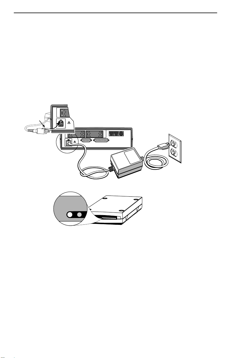
Installing the Power Supply and Cord
1. Insert the 4-prong plug into the POWER jack.
When inserting the plug at the rear of the FrameSaver unit, align the plug with the
notch above the POWER jack. Make sure the locking tab snaps securely into the
jack.
2.
P
O
R
Locking
Tab
T
1
Insert the 3-prong plug
POWER
P
O
R
T
1
DSX COM
POWER
P
O
R
T
2
MODEM NET DBM
2.
into an ac outlet.
3-Prong
Grounded
AC Outlet
Power Cord /
Transformer
3.
The front panel
OK LED lights.
OK
ALM
3.
4. Plug the power cord into the grounded power outlet.
Verification Check:
Did any LEDs light?
– If yes, the FrameSaver unit has power.
– If no, refer to
T roubleshooting
in the User’s Guide.
3
99-16629

Connecting the COM Port to an Asynchronous Terminal
The FrameSaver unit must first be directly connected to a VT100-compatible
asynchronous terminal or a PC providing VT100 terminal emulation to set up
access and management of the unit.
1. Configure the terminal or PC to be compatible with the FrameSaver unit:
– COM Port in use by your PC: COM1 or COM2.
– COM Port Baud Rate is set to 19.2 kbps.
– Character length is set to 8 data bits.
– Parity is set to none.
– Stop bit is set to 1.
– Flow Control is set to None.
2. Insert the DB25 end of the EIA-232 cable into the FrameSaver unit’s COM port.
COM
Port
P
O
R
T
1
DSX COM
POWER
To Connect to a PC
or Async Terminal
P
O
R
T
2
MODEM NET DBM
99-16628
3. Insert the other end of the cable into the terminal or PC.
4. Tighten the screws on each side of the connector to secure them.
5. Press Enter on the keyboard (or Return, depending upon your keyboard) to display
the Main Menu.
Verification Check:
Did the Main Menu appear on the asynchronous terminal?
– If so, continue with the installation.
– If not, recheck terminal and FrameSaver unit compatibility (see settings in
Step 1), or press the Enter key.
Refer to
Troubleshooting
in the User’s Guide for other possible explanations.
4

A Quick Guide to Configuration
The FrameSaver unit should operate using the default (factory-set) configuration
options, except for the changes specified in these installation instructions. Refer to the
following table for help navigating the menus.
Press the . . . To . . .
Esc key Go back one screen or menu level. To see a visual
representation of the menu levels, see
the Quick Reference.
Menu Hierarchy
in
Tab key, or
up (↑) and down (↓), or
left (←) and right (→), or
arrow keys
Enter or Return key Complete the menu or option selection.
Spacebar Display the next available setting when changing a
As an example, follow these steps to go to the Configuration Edit/Display menu so you
can start setting up the unit.
To load a configuration for editing:
1. From the Main Menu, press the down arrow key twice so the cursor is on
Configuration.
2. Press Enter to display the Configuration menu. The Load Configuration From
menu appears.
3. Press Enter to select Current Configuration. The cursor is already on this selection.
The Configuration Edit/Display menu appears.
This sequence of steps would be shown as the menu selection sequence:
Move the cursor from one menu item to the next.
configuration option. All the available settings for an
option appears at the bottom of the screen.
Main Menu→Configuration
To save a configuration option change:
1. Press Ctrl-a to switch to the screen function keys area at the bottom of the screen.
2. Type s or S (S
3. Press Enter again to save your changes to the Current Configuration.
4. Press Esc until the Configuration Edit/Display menu reappears to continue
configuring the unit.
Press Ctrl-a, type m (M
ave) and press Enter. The Save Configuration To menu appears.
ainMenu), and press Enter to return to the Main Menu.
The following sections guide you through installation and setup of the FrameSaver unit.
5

The FrameSaver unit is set to automatically configure the following:
Time Slot Assignment
Auto-Configuration
It is assumed that the unit is configured for factory default settings at the start of the
installation, and that the automatic configuration features will be used. See
Assignment
these features.
on page 7 and
Automatic Configuration
on page 9 for information about
Time Slot
Verifying that Self-Test Passed
To verify that the unit passed its self-test, go to the System and Test Status screen.
Main Menu→Status→System and Test Status
The results of the self-test appears directly under the screen title.
If any failure messages appear, reset the unit by disconnecting, then reconnecting the
power cord. The unit will perform the self-test again. If the failure reappears, call your
service representative for assistance.
Setting the System Clock
1. Select System Information.
Main Menu→Control→System Information
2. Move the cursor to the Date, then the Time field to enter:
– Date in the mm/dd/yyyy format (month/day/year)
– Time in the hh:mm format (hours:minutes)
ave the settings.
3. S
Assigning the Node IP Address
1. Set up the node.
Main Menu→Configuration→Management and Communication→Node IP
2. Minimally, enter the following options:
– Node IP Address
– Node Subnet Mask
ave the configuration.
3. S
6

Setting Up Physical Interfaces
1. Select each interface’s physical configuration options.
Configuration→Network→Physical
→
Configuration
Configuration
If installing a FrameSaver SL V NAM with an ISDN DBM, postpone configuring the
DBM interface until later.
2. Configure the Network and DSX-1 interfaces to match the network provider’s
settings. Be sure to enable the Interface Status option for these interfaces.
(The network interface is already enabled on a FrameSaver SL V NAM.)
Configure Data Ports to match the DTE’s settings. If Port-2 will be used, enable the
Port Status option for the port.
3. S
ave the configurations.
Data Ports→Physical
→
DSX-1
(if the DSX-1 interface will be used)
Setting Frame Relay Characteristics
When installing a FrameSaver SL V NAM, frame relay characteristics must be
configured for the network and data ports.
1. Select the interface’s frame relay configuration options.
Configuration→Network→Frame Relay
Configuration
2. Configure each interface according to the local management interface (LMI) and
assigned line conditions supplied by the service provider.
3. S
ave the configurations.
→
Data Ports→Frame Relay
Time Slot Assignment
FrameSaver SL V NAM frame relay (network) time slots are discovered automatically
when Time Slot Discovery is enabled (the default setting) on the Frame Relay
Network 1 Assignments screen. This feature can be disabled if you want to manually
configure time slots.
Assigning Time Slots/Cross Connections
See
additional information about this feature.
in
Configuration
7
of the User’s Guide for

Setting Up the Modem
The unit has an integral modem for remote management. It is already set up for dial-in
access to the unit, with Port Use set to Terminal.
If using the modem for dialed IP network connectivity (SNMP, Telnet, FTP, or
trap dial-out):
1. Select Modem Port.
Configuration→Management and Communication→Modem Port
2. Minimally, change Port Use to Net Link, and assign the interface’s IP Address and
Subnet Mask if it is different from the Node’s. Change Link Protocol to SLIP, if
necessary (PPP is the default setting).
3. S
ave the configuration.
Setting Up Call Directories if Trap Dial-Out Is Desired
1. Set up directory phone numbers.
Main Menu→Control→Modem Call Directories
2. Select Directory Number A (for Alarm).
3. Enter the phone number(s). V alid characters include:
– ASCII text
– B for blind dialing
– W for wait for dial tone
– P for pulse dialing unless B specified
– T for tone dialing unless B specified
– Space, underscore ( _ ), comma (,) for a 2-second pause, and dash (–)
readability characters
ave the phone number(s).
4. S
8
 Loading...