

Paradyne SLV, FrameSaver SLV Installation Instructions Manual

TM
1
FrameSaver SLV
Network Access Module (NAM)
Installation Instructions
Document Number 9000-A2-GN1J-30
May 1999
Product Documentation on the World Wide Web
We provide complete product documentation online. This lets you search the
documentation for specific topics and print only what you need, reducing the waste of
surplus printing. It also helps us maintain competitive prices for our products.
Complete documentation for this product is available at www.paradyne.com.
Select
Library →Technical Manuals →FrameSaver Frame Relay Devices.
Select the following document:
9128-A2-GB20
FrameSaver SL V 9126/9128 User’s Guide
To request a paper copy of a Paradyne document:
Within the U.S.A., call 1-800-PARADYNE (1-800-727-2396)
Outside the U.S.A., call 1-727-530-8623
Before You Begin
Make sure you have:
A small, flat-blade screwdriver.
A small, Phillips screwdriver if installing an ISDN PRI DBM.
FrameSaver SL V ISDN Dial Backup Module (DBM) Installation Instructions
(Document No. 9000-A2-GN19) if installing an ISDN PRI DBM.
If a FrameSaver NAM with DBM is being replaced, the DBM must be transferred to
the replacement NAM.
Configuration information for the FrameSaver unit being installed or replaced.

496-15149
2
Appropriate cables:
— DSX cable
— Data port cables
— COM port-to-terminal or COM port-to-PC cable
— Modem cable
See the User’s Guide for additional information on:
Troubleshooting
Cables, Connectors, and Pin Assignments
Technical Specifications
Equipment List
Package Checklist
Verify that your package contains the following:
FrameSaver SLV NAM
NAM I/O card
T1 network cable
ISDN PRI cable, if applicable
FrameSaver SL V 9126/9128 Quick Reference
(Document No. 9128-A2-GL10)
Visit the Paradyne World Wide Web site at www.paradyne.com to register your
warranty. Select
Service & Support→Warranty Registration.
Safety Instructions
Please refer to the
EMI Warnings
and
Important Safety Instructions
beginning on
page 24.
!
HANDLING PRECAUTIONS FOR STATIC-SENSITIVE DEVICES
This product is designed to protect sensitive components from
damage due to electrostatic discharge (ESD) during normal
operation. When performing installation procedures,
however, take proper static control precautions to
prevent damage to equipment. If you are not sure
of the proper static control precautions, contact
your nearest sales or service representative.
98-16202
N
E
T
1
D
B
M
M
D
M
P
O
R
T
1
P
O
R
T
2
C
O
M
D
S
X
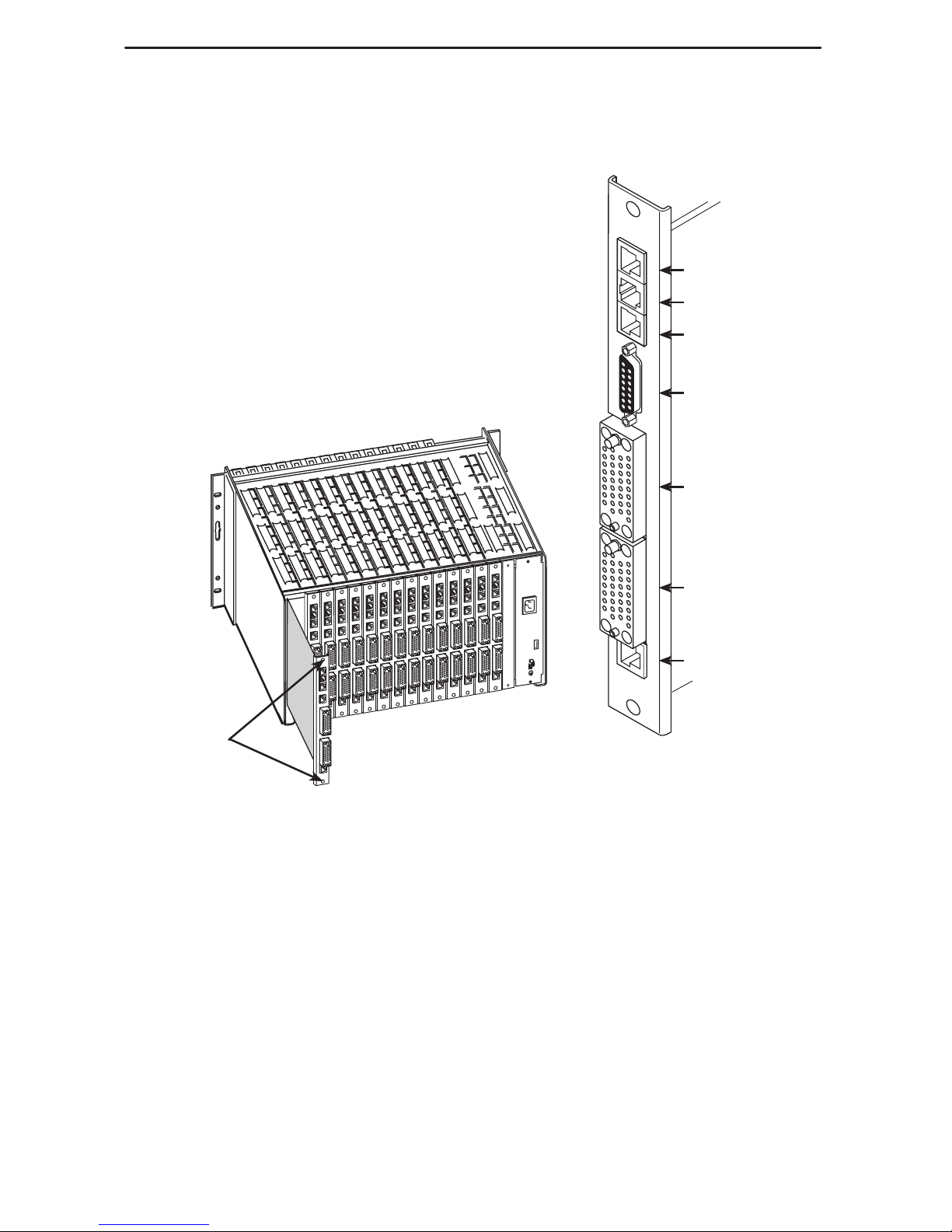
SINGLE
T1 NAM
Network
ISDN PRI DBM
Modem
DSX-1
Communications
Port
Port 1
Port 2
NAM
I/O Card
3
Installing the I/O Card
The NAM’s I/O card provides the network, DSX, DBM,
modem, DTE and COM port connections. The I/O card
inserts directly behind the NAM that it supports in the
access carrier.
1. Remove the I/O card from the shipping box.
To avoid damaging the card, handle by the top and
bottom edges only.
2. At the rear of the carrier, align the I/O card with the
upper and lower tracks of the slot.
Push gently toward the midplane until it stops and
the card cannot be pushed any further.
99-16203-02
Rear View
Captive
Screws
3. Using a small, Phillips screwdriver, alternately tighten the
captive screws until they are all snug.
98-16209
Ejector
Latches
Front View
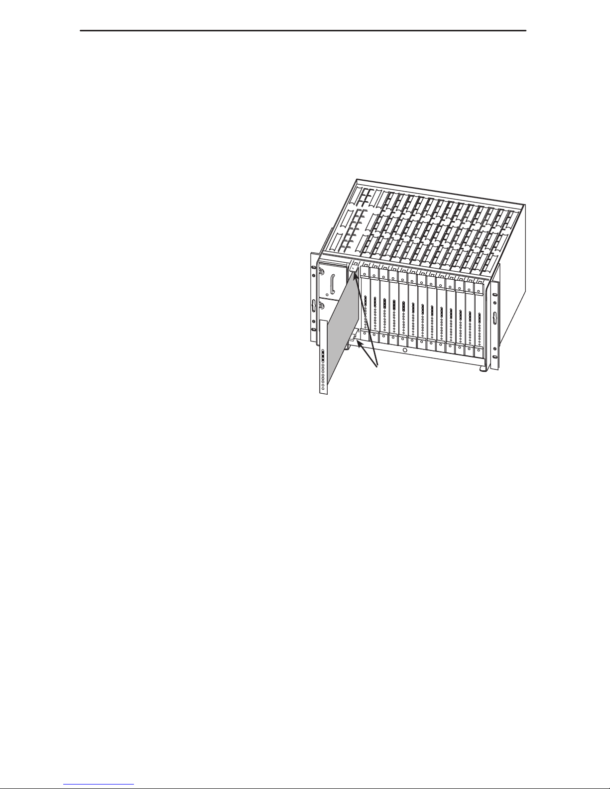
4
Installing the NAM into a Multislot Housing
The illustration shows the 14-slot access carrier as the housing.
CAUTION:
Be sure that you install the NAM in the correct slot so that it mates with its
matching I/O card. Otherwise, you could damage your card.
1. Remove the NAM from the shipping
box. Handle only by the top and
bottom edges to avoid damaging
the card.
2. At the front of the carrier, align the
NAM with the upper and lower
tracks of the appropriate slot.
3. Slide the NAM into the tracks until it
seats with the midplane connectors.
Use care not to force the card or
bend any pins.
4. Close the carrier’s upper and lower
ejector latches to lock the card into
place, then tighten the captive
screws on the ejector latches.
Verification Check:
Did the OK LED light?
– If yes, the FrameSaver unit has power.
– If no, refer to
Troubleshooting
in the User’s Guide.
5
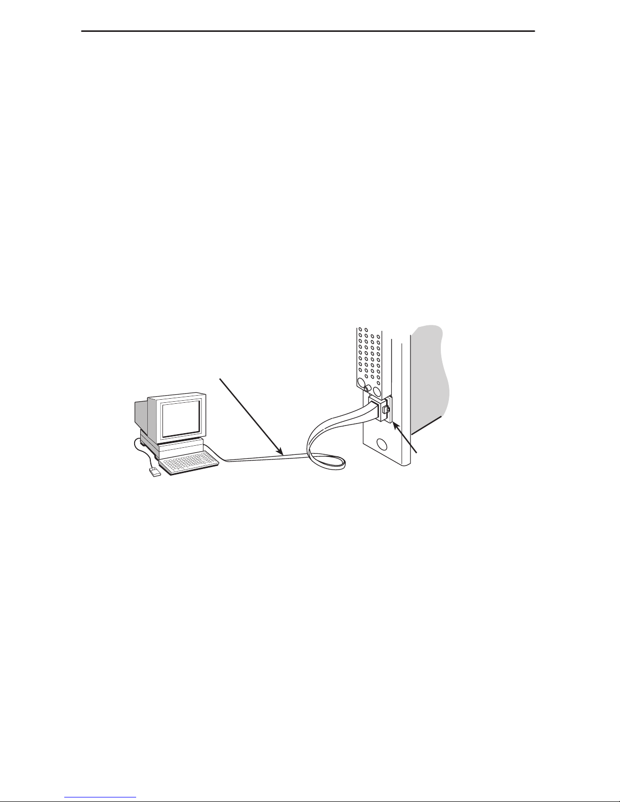
Connecting the COM Port to an Asynchronous Terminal
The FrameSaver unit must first be directly connected to a VT100-compatible
asynchronous terminal or a PC providing VT100 terminal emulation to set up access
and management of the unit.
1. Configure the VT100-compatible async terminal or PC to be compatible with the
FrameSaver unit:
– COM Port in use by your PC: COM1 or COM2
– COM Port Baud Rate is set to 19.2 kbps
– Character length is set to 8 data bits
– Parity is set to none
– Stop bit is set to 1
– Flow Control is set to None
2. Insert the 8-pin end of the cable into the COM port for the appropriate slot.
3. Insert the other end of the cable into the VT100-compatible asynchronous terminal,
PC, or async terminal providing VT100 terminal emulation to set up the unit.
P
O
R
T
2
C
O
M
COM
98-16208a
COM Port-to-Terminal/Printer
or
COM Port-to-PC Cable
4. Press Enter on the keyboard to display the Main Menu.
Verification Check:
Did the Main Menu appear on the async terminal?
– If yes, continue with the installation.
– If no, recheck terminal and FrameSaver unit compatibility (see settings in
Step 1), or press the Enter key.
Refer to
Troubleshooting
in the User’s Guide for additional information.

6
A Quick Guide to Configuration
The FrameSaver unit should operate using the default (factory-set) configuration
options, except for the changes specified in these installation instructions. Refer to the
following table for help to navigate through the menus.
Press the . . . To . . .
Esc key Go back one screen or menu level. To see a visual
representation of the menu levels, see
Menu Hierarchy
in
the Quick Reference.
Tab key, or
up (↑) and down (↓)
arrow keys
Move the cursor from one menu item to the next.
Enter or Return key Complete the menu or option selection.
Spacebar Display the next available setting when changing a
configuration option. All the available settings for an
option appears at the bottom of the screen.
As an example, follow these steps to go to the Configuration Edit/Display menu so you
can start setting up the unit. To load a configuration for editing:
1. From the Main Menu, press the down arrow key twice so the cursor is on
Configuration.
2. Press Enter to display the Configuration menu. The Load Configuration From
menu appears.
3. Press Enter to select Current Configuration. The cursor is already on this selection.
The Configuration Edit/Display menu appears.
This sequence of steps would be shown as the menu selection sequence:
Main Menu→Configuration→Load Configuration From:→Current Configuration
To save a configuration option change:
1. Press Ctrl-a to switch to the screen function keys area at the bottom of the screen.
2. Type s or S (S
ave) and press Enter. The Save Configuration To menu appears.
3. Press Enter again to save your changes to the Current Configuration.
4. Press Esc until the Configuration Edit/Display menu reappears to continue
configuring the unit.
Press Ctrl-a, type m (M
ainMenu), and press Enter to return to the Main Menu.
In the sections that follow, only the minimum option changes required are included so
you will have a quick and trouble-free installation.
See the configuration option tables in the User’s Guide for more information about
configuration options.

7
Installing and Setting Up the FrameSaver SLV
To complete the installation, you must:
Verify that self-test passed.
Configure the FrameSaver unit.
Connect to the network and continue configuration.
Connect to the modem.
Connect to the ISDN, if applicable.
Connect to the DSX, if applicable.
Connect to the DTE(s).
Check the connections.
NOTE:
Follow these instructions as they are presented. The system should be configured
first before connecting the cables. Otherwise, installation time will be increased.
Verifying that Self-Test Passed
Before starting to configure the FrameSaver unit, confirm that the unit passed the
self-test.
1. Follow this menu selection sequence from the Main Menu, pressing Enter after
each selection:
Main Menu→Status→System and Test Status
2. Check the Self-Test Results column (in the center of the System and Test Status
screen).
– If Passed appears, the FrameSaver unit successfully completed the self-test.
– If any failure messages appear, reset the unit by removing and reinserting the
NAM. The unit will perform the self-test again. If the failure reappears, call your
service representative for assistance.

8
Configuring the FrameSaver Unit
To configure the FrameSaver unit:
Set the system clock.
Assign the Node IP Address.
Set up Network physical interface, and DSX-1 physical interface, if applicable.
Enter time slot assignments, if applicable.
Set up Data Port physical interface(s).
Set up modem call directories if dial-out traps are desired.
Set up management.
Set up Automatic Frame Relay Discovery Configuration.
Set up Automatic Backup Configuration, if an ISDN DBM if installed.
Setting the System Clock
To set up the system clock:
1. Select Date & Time.
Main Menu→Control→Date & Time
2. Move the cursor to the first field and enter the:
– Date in mm/dd/yyyy format (month/day/year).
– Time in hh:mm format (hours:minutes).
3. S
ave the date and time.
Assigning the Node IP Address
1. Set up the node.
Main Menu→Configuration→Management and Communication→IP Node
2. Minimally, enter the following options:
– Node IP Address
– Node Subnet Mask
3. S
ave the configuration.

9
Setting Up the Network and DSX-1 Interfaces
1. Select the network interface’s physical configuration options.
Configuration→Network→Physical
2. Configure the interface to match the network provider’s settings.
3. S
ave the configuration and return to the Network menu.
4. Select Frame Relay.
5. Configure the frame relay characteristics to match the network provider’s settings.
6. S
ave the configuration and return to the Configuration Edit/Display menu.
7. If applicable, select DSX-1.
8. Enable the interface and configure the unit to match the service provider’s settings.
9. S
ave the configuration.
Entering Time Slot Assignments
Frame relay time slots are discovered automatically if Time Slot Discovery is enabled
on the Frame Relay Network 1 Assignments screen, which is the default setting).
Configuration→Time Slot Assignment→Frame Relay Network Assignments
This feature can be disabled, if desired, so that Frame Relay-to-Network Time Slot
Assignments can be manually configured.
Use the following procedure if additional network time slots need to be cross-connected
to the DSX-1 interface. See
Assigning Time Slots
in
Configuration Options
of the User’s
Guide to read more about assigning time slots for a FrameSaver 9124, 9126, or 9128.
1. For the DSX-1 interface, select DSX-1 from the Configuration Edit/Display menu
and enable Interface Status.
2. Return to the Configuration Edit/Display menu.
3. Select Time Slot Assignment, then Frame Relay Network Assignments.
4. For the DSX-1 interface, map the desired time slots to the DSX-1 interface.
– Press the Tab key to move the cursor to the desired network interface time slot.
– Press the spacebar until the appropriate DSX-1 channel is displayed, Frame
Relay (FrameRly1) or Available. Frame Relay is the default.
– Repeat the process until all the desired time slots have been assigned to a
DSX-1 channel.
5. S
ave the configuration and return to the Configuration Edit/Display menu if no
DSX-1 channels will be assigned to network time slots.
If configuring DSX-to-network time slots, proceed to Step 6.
6. Return to the Time Slot Assignment menu and select DSX-1 to Network
Assignments.
 Loading...