

Paradyne FrameSaver NP 100, FrameSaver NP 64+, FrameSaver NP 110, FrameSaver NP 120 Installation Quick Reference Manual

FrameSaver® NP
Installation & Quick Reference Guide
FrameSaver NP Models 64+, 100, 110 and 120
Document Number 980-000-0272B
August 2000
This Quick Reference Guide provides an over view on how to inst all a FrameSaver NP
Model 64+, 100, 110 or 120 unit. This includes making the physical connections between the unit, netw ork, DTE device(s), and telephone line. It also tells you ho w to find
more detailed information about your FrameSaver NP.
Product Documentation on the World Wide Web
We provide complete product documentation online. This lets you search the documentation for specific topics and print only what you need, reducing the waste of surplus printing. It also helps us provide timely product update information and maintain
competitive prices for our products.
Complete documentation for these products is available at
www.paradyne.com
.
Select Library
→
Technical Manuals →
FrameSaver NP (NetPath) Frame Relay Digital Access Units
Select the appropriate document from the documentation list:
FrameSaver NP 64+ User’s Manual - Installat ion Guide, Publicatio n # 980-001- 0221
FrameSaver NP 100 U s er’s M an ual - Installatio n G u id e , P ub licati o n # 980-001-0210
FrameSaver NP 110 U s er’s M an ual - Installatio n G u id e, P ub l ication # 980-001- 024 0
FrameSaver NP 120 U s er’s M an ual - Installatio n G u id e, P ub l ication # 980-001- 023 0
116

Getting Started
Before installing or starting to use the FrameSaver NP, you shou ld:
•
Install the User’s Manual - Installation Guide so that you can access all the
installation, configuration, and operating information about the unit.
•
Print sections you may want to reference.
User’s Manual - Installation Guide
The manual is in PDF fil e format. Your PC shou ld be using Micros oft Windows 3.1 or
above, and have Adobe Acr obat Reader inst alled for brows ing or printing this manual.
Adobe Acrobat Reader may be obtained free fro m Adobe Systems Incor porated, from
their Web Site at www.adobe.com.
Using Adobe Acrobat Reader
Adobe Acrobat Reader is used just as you would most word processing or text editing
programs. Start Adobe Acrobat Reader and open the file containing the FrameSaver
NP User’s Manual - Installation Guide. You can simply scroll through the pages, or
use the Bookmarks along the left side to move around the manual or the tables in the
front of the manual.
To print the manual or a selection of pages, select Print... from the F
ile menu and then
select the range of pages you wish to print. Select OK to begin printing.
Ordering a Hard Copy of the User’s Manual
Contact Paradyne Corporation at the address on the back of this Guide to ob tain a printed copy of a FrameSa ver NP User’s Manual - Installation Guide. Always specify the
“latest revision” for each publication number:
Safety Instructions
Before proceeding with the installation, carefully rea d the Equipment I nterference Notice, Important Safety Instructions and Preface s ections of the FrameSaver NP User’s
Manual - Installation Guide.
Contact your service representative, distr ibutor or s ales repres entative to ord er cables .
T1 or DSX network cable, RJ-48, twisted pair 135-982-0006
Dial Line (POTS) cable, RJ-11 connector 135-007-7200
ISDN BRI network cable, RJ-49 connector 135-981-0006
Console cable (to AUX2), DB-9 connector 135-000-0464
Console cable (to AUX2), D B -25 connector 135-007-0400
AUX Port to router console port cable, DB-25 connector 135-008-0400
AUX Port to Cisco router console port, RJ-45 type connector 135-990-0006
2

Before You Begin
Ensure you have the following:
•
A dedicated, grounded, circuit breaker p rotected power outlet within six feet o f
the FrameSaver NP unit.
•
A suitable location for the unit that is clean, well-lit, ventilate d and free fro m
environmental extremes.
•
One to two feet of clearance for cable connections to the unit.
Package Checklist
Verify that the packaging contains the following:
•
FrameSaver NP unit
•
Unit power cord or AC Power Pack with cord
•
If ordered, optional wall-mount or rack-mount bracket assembly.
In addition, you will need Input/Output cables if not already supplied. These cables are
listed for each FrameSaver NP Model on pages 13 - 15 of this guide.
Mounting the FrameSaver NP
FrameSaver NP units come equipped with rubber feet for table or shelf-top placemen t.
Optional adapter brackets are available for wall mounting (Model 64+ includes wallmount key-holes in its base) and standard 19" or 24" rack mounting. To attach and
mount adapter brackets, follow the instructions supplied with the mounting adapters.
Allow sufficient space for cooling and access to the front panel indicators for troubleshooting in all installations.
Power Up a FrameSaver NP 64+
Make Power Connections
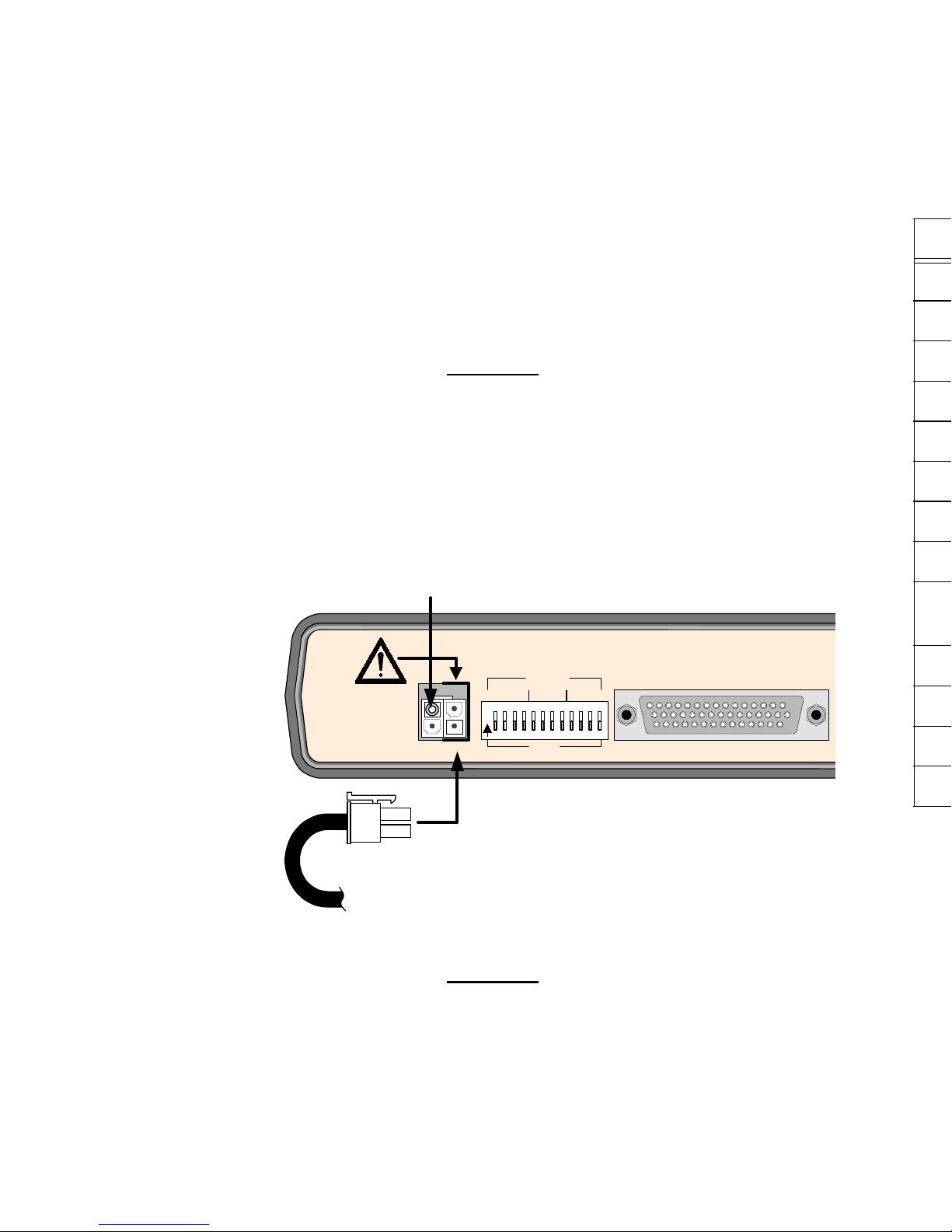
1. Plug the 2-pin keyed and locking connector at the end of the cord from the AC
Power Pack into the right-most pins of the 4-pin Power Connector located on the
rear of the FrameSaver NP 64+, just to the right of the alert marking.
CAUTION
The power connectors are keyed and fit easily together
when oriented correctly with the locking clip toward the
top of the unit. Do not force the connectors together.
CAUTION
The 2-pin keyed plug fits easily into the two RIGHT-SIDE pins of the 4-pin
Power Connector, and must only be inserted there. The FrameSaver NP
unit will be damaged if the plug is forced into the other side.
Contact your service representative, distr ibutor or s ales repres entative to ord er cables .
DATA PORT
SEE
USERS
MANUAL
POWER
PAC
O
N
1234 5 6 7 8 9 101112
DLCI
x1x100 x10
DIGITS
2-Pin
Connector
from
Power Pack
Plug into RIGHT side
Pins ONLY
Blocking Safety Plug
(Remove only when insta lling optional
Power Control Unit)
DDS network cable, RJ-48, twisted pair 135-982-0006
Dial Line (POTS) cable, RJ-11 connector 135-007-7200
ISDN BRI network cable, RJ-49 connector 135-981-0006
EIA-232 Data Port (DTE) cable 135-000-0400
EIA-530 Data Port (DTE) cable 135-002-0400
EIA-530A Data Port (DTE) cable 135-003-0400
ITU-X.21-NS Data Port (DTE) cable 135-005-0400
ITU-V.35 Data Port (DTE) cable 135-001-0400
ITU-V.35 Data Port (DTE) cable to Cisco router serial port,
HD-60 connector
Console cable (to AUX2), DB-9 connector 135-000-0464
Console cable (to AUX2), D B -25 connector 135-007-0400
AUX Port to router console port cable, DB-25 connector 135-008-0400
AUX Port to Cisco router console port, RJ-45 type connector 135-990-0006
2. Plug the Power Pac at the other end of the power cord into an AC outlet.
3. The unit will go through the following power-up sequence:
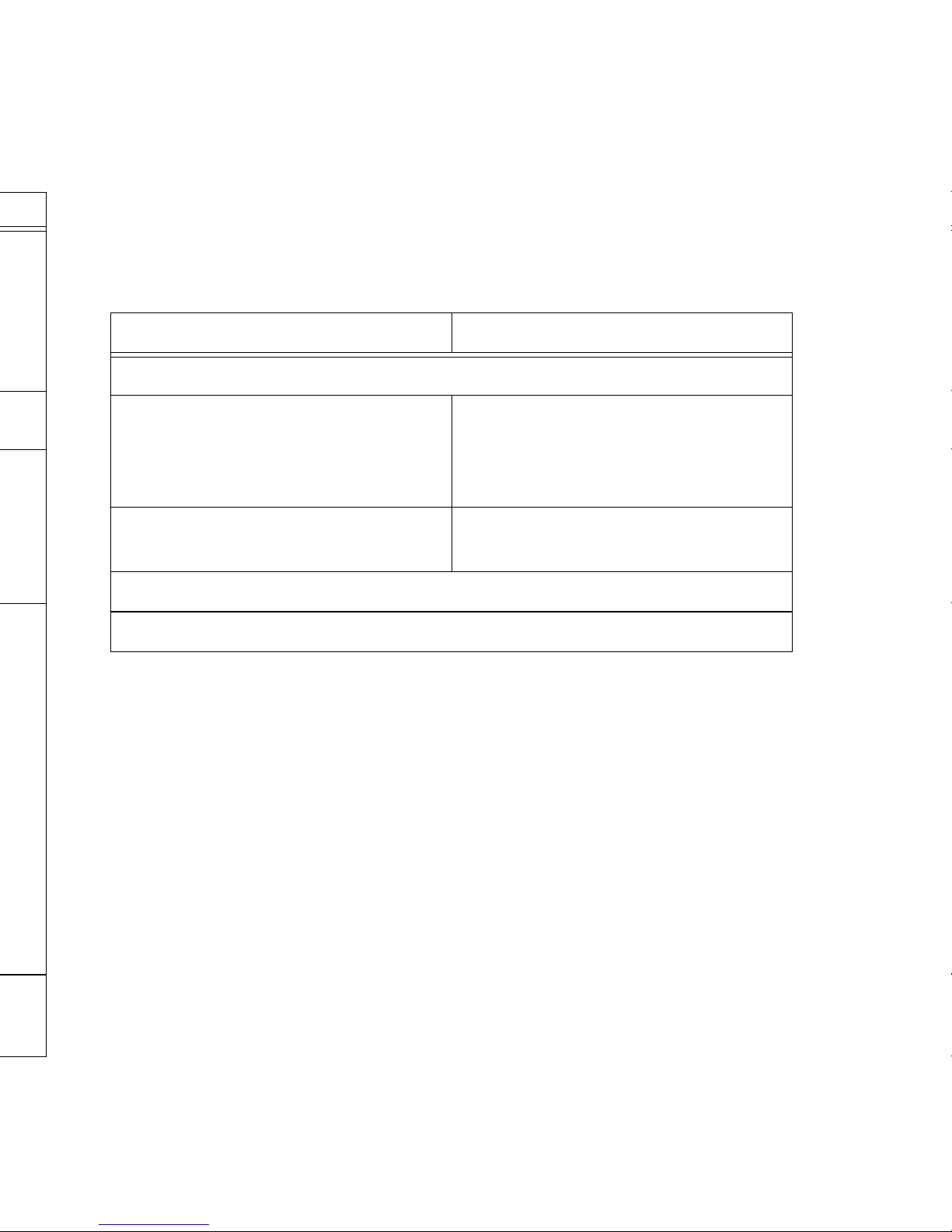
FrameSaver NP 64+ Power-Up Sequence
If the LED indicat ions ar e not as describ ed above , ref er to S ection 5, “Diag nostics” of
the FrameSaver NP 64+ User’s Manual - Installation Gu ide.
If operation l ooks normal, u nplug the FrameSaver NP befo re making inpu t/output con nections.
If an optional Power Control Unit (PCU) is to be installed with this FrameSaver NP,
refer to the instructions provided with the PCU and install it now.
Proceed to Making Network and Input/Output Connections on page 9 of this guide.
Basic FrameSaver NP 64+ FrameSaver NP 64+ with ISDN
POWER LED l ights and stays on.
READY LED may flash several times,
then remain OFF during self-test
(approxi mately 45 seconds).
READY and ISDN READY LEDs
may flash several times, then remain
OFF during self-test (approximately 45
seconds).
READY LED is ON steady after
completion of self-test.
READY and ISDN READY LEDs are
ON steady after completion of self-test.
The DDS ALARM and FR MGMT. LEDs should not be flashing together.
All other LED indications should be ignored at this time.
512
 Loading...